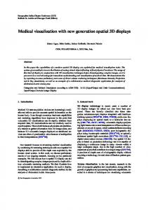
3D Approach to the Visualization of Parallel Applications and Grid Monitoring Information Lucas Mello Schnorr†‡ , Guillaume Huard‡ , Philippe Olivier Alexandre Navaux† † Instituto
de Inform´atica Universidade Federal do Rio Grande do Sul CEP 91501-970 - Porto Alegre - RS - Brazil E-mail: {lmschnorr,navaux}@inf.ufrgs.br Abstract— Parallel computing is increasingly used to provide more performance to applications that need tremendous computational power. The main characteristics of distributed parallel machines are heterogeneity, dynamism and size. They influence directly the way the application and platform monitoring tasks are performed, especially when analyzing a large quantity of information collected in a topologically complex machine. This paper describes our efforts to provide parallel programmers and Grid users a new way to visualize monitoring data. Using a three dimensional representation and information visualization techniques, we aim at bringing rich topological information to the rendered scene. It results in an immersive and human readable representation of complex monitoring data, suited to Grid environments. We first review known techniques in information visualization context, especially those that address the case of hierarchical information, and we discuss about their use in our context. Then, we propose a new 3D approach that combines the classical space-time visualization of application traces with the representation of the underlying architecture topology. Finally, we present experimental results obtained throught the visualization of parallel applications in our prototype.
I. I NTRODUCTION Parallel and distributed computing systems are used today to offer applications more computational power. One example is grid infrastructures, also known as virtual organizations [8]. The main characteristics of these systems are their heterogeneity (from the resources interconnection to the software organization), their dynamism and scale (the number of resources may vary through time and possibly become large) and their topological complexity (interconnection organization). Dealing with parallel applications in these systems involves many tasks such as deployment, security and resources management. One of these tasks, the resources and application monitoring, is especially useful to the system administration (platform state information), grid middleware (resources and application management), application debugging (deadlocks detection) and performance tuning (bottlenecks identification). The data monitored in these cases can range from details about applications to network and resources metrics. The analysis of all this information is often complex, partially due to the large number of resources that can be involved in the monitoring task and partially due to the topological complexity, dynamism and heterogeneity of platforms such as Grids. One way to ease the analysis of this complex information is
‡ Laboratoire
LIG - MOAIS INRIA Project ENSIMAG - 51 avenue Jean Kuntzmann 38330 - Montbonnot Saint Martin - France E-mail:
[email protected] to use elaborated visualization techniques, that can help the analyst to find patterns in the monitoring data. The visualization is already widely used in existing architectures: for instance, in clusters, where data is simpler (uniform, low scale), to visualize the behavior of parallel applications or the platform load state. Nevertheless, the information presentation is often based on two dimensional Gantt Charts in which the platform topology is not particularly outlined. When dealing with Grids, this is not sufficient as the platform might have a deep hierarchical organization, strong resources heterogeneity or a larger number of different metrics to monitor. The question we try to address is how to organize this information in space in order to obtain an understandable and significant visualization. A large number of visualization techniques were developed during the last 20 years to analyze information extracted from databases, statistical studies and other areas involving large data sets. Some of these efforts were applied in Grid computing through the use of visualization tools such as Paradyn [1], Paj´e [5] and the work of Reed [24]. Our approach to deal with visualization of Grid environments and applications involves both the use of information visualization techniques and topological information. This paper presents a different way to visualize the monitoring data collected in Grid environments. It makes use of a three dimensional view to combine related data: the hardware resources and the application activity. Moreover, this approach can be applied to any pair of related information streams and remains as generic as possible. In this approach, two axis are used to represent the Grid resources and outline their topology while the third axis is used to represent the evolution of time. Application activity information is thus injected into this 3D representation. The benefits brought by this approach over classical Gantt charts is that a two dimensional space is available to build a representation of the platform topology. The paper is organized as follows: section II presents known information visualization techniques and discusses about their use in Grid environments. Section III describes in details our 3D approach to visualize Grid and parallel applications monitoring data. Section IV shows the results of our 3D Visualization tool, named Triva. Section V presents related work and, finally, section VI gives a summary of our achievements and future works.
II. I NFORMATION V ISUALIZATION E LEMENTS APPLIED TO PARALLEL M ACHINES Two dimensional display of node-link diagrams, depicted in figure 2(a), is the usual way to visualize hierarchical information [19]. The nodes are connected to others by links and can be labeled with additional information. In order to better explain hierarchical visualizations, we will take Grid’5000 [3] as our main heterogeneous platform example. Grid’5000 is a nation-wide interconnection of clusters of workstations geographically spread over France totalizing 5000 processors cores. The interconnection is mainly made of three different kinds of networks (local ethernet, local high performance such as myrinet, and optical fiber backbone). Figure 1 presents a platform overview, showing the fiber backbone interconnection between the geographical locations taking part of the project. Because each cluster that belongs to Grid’5000 is an homogeneous group of resources, we name this kind of Grid a Lightweight grid (limited heterogeneity, strong hierarchy).
Fig. 1.
Grid’5000 network organization using the fiber backbone.
As we can see in figure 2(a), we can use a node-link diagram to represent the hierarchy induced by the Grid’5000 backbone when taking Grenoble as root of the tree. This figure gives a pretty good picture of inter-sites network distance and site connectivity (Paris and Lyon have both a large arity). Nevertheless, we can notice that parts of this figure are empty (top left and top right) and that sites relative size cannot be represented intuitively(labeling is not visually sound). A. Treemap Representations The treemap technique is a solution that provides a better exploitation of the screen space [13]. Instead of drawing nodes and links between them, it exploits the whole screen space using a recursive space-division algorithm. This algorithm starts at the root of the hierarchy, divides the available space among the direct children of the current node and applies itself recursively to the space part given to each child. Examples of treemaps utilization include network monitoring with security purposes [17], grid resource monitoring
(a)
(b)
Fig. 2. (a) Hierarchy visualization of Grid’5000 network organization from the Grenoble point-of-view (b) Treemap associated with that point-of-view.
data visualization [21] and visual analysis of stock market [25]. These multiple applications of the treemap technique demonstrate its potential. We could apply directly the treemap technique on the Grid’5000 hierarchy presented in figure 2(a) resulting in the treemap presented in figure 2(b). Nevertheless, in this figure, although the drawing space is fully utilized, the relative size of different sites is completely irrelevant and the hierarchical structure is less obvious. When using treemaps to visualize the platform such as Grid’5000, one should take advantage of the representation to outline relevant platforms characteristics. Thus, if we organize the platform hierarchical structure into Grid (the whole platform), Sites (each geographical organization), Clusters (each homogeneous group of workstation) and Nodes (each workstation), we outline its geographical organization. Additionally using the number of nodes to determine rectangles size, we end up with the treemap presented in figure 3 to represent Grid’5000. In this figure, the platform hierarchy appears less clearly than in figure 2(a). But taking advantage of bold and dashed line, we can still emphasize the hierarchy levels: we can notice that Rennes hosts 4 clusters of respective size 64, 32, 99 and 66, that Orsay hosts 3 clusters of respective size 126, 186 and 30, and so on. Furthermore, because of rectangles dimensions we can intuitively visualize the relative size of the different components of the platform thus gaining quantitative information about the platform. B. Interaction Mechanisms When using a graphical visualization, users are interested in interaction mechanisms, like zooming, animations and online information updates. These facilities improve the user perception of specific parts of the information, enabling him to analyze deeply its application and platform behavior. Zooming, for instance, could be applied on the example of figure 3 by choosing one of the sites. After this operation, the chosen site would occupy the whole screen and sub parts of the site would then have enough room to display additional information. The graphical animation together with online updating can also be applied by dynamically change the graphical visualization. Resizing rectangles and changing their colors to reflect platform state are some examples. In this case, changes are caused by continuous information updates coming from the monitoring system. Another type of graphical interaction
number of links. The figure 4(b) presents an example of this approach.
(a) Fig. 3. Logical Hierarchical Definition of Grid’5000 based in the number of nodes, and a division in Grid - Sites - Cluster - Nodes.
mechanism is constituted by distortion techniques [4], which magnify only specific parts of the representation. The fish-eye technique [22] is a good example of such technique. It helps the user to obtain details about a picture area without losing its context (as opposed to a simple zoom). C. Parallel Applications Visualization Most of these visualization techniques present the data from a resources point of view. In the Grid’5000 example from figure 3, the visualization contains the node count for each site. Of course it would be interesting for the user to combine resources visualization with application information such as the number of threads running on each site, node, or even more precisely on each core. This combined approach still needs resources as basis in order to ease the understanding of the relationship between resources events (load, contention, under utilization and others) and application execution. The use of treemap could constitute this basis (as they are often used to inform the user about resources in use [7]). We could also combine this idea with the techniques of software calls visualization presented by Holten [12] and adapted to Grid contexts: the parallel application communications would thus be visualized on top of a treemap (figure 4(a)). Processes in each site would be represented by circles inside the rectangles while communications between them by edges (possibly directed). Notice that this kind of representation should also be designed to operate nicely with interaction mechanisms (for instance when zooming toward a single process or when updating the number of processes executing within a node). Of course, rectangular treemaps should not be considered as the only way to represent resources information. For instance, if communications between processes is as important as cluster size, it is possible to use a circle as base space for resources and dedicate the interior part of this circle to represent communication streams between machines. The approach was used by Holten [12] to show links bundles made of a large
(b)
Fig. 4. Figures extracted from [12]. Examples that can be used in Grid context showing communications and processes: (a) treemap based and (b) circles based.
III. T HE 3D A PPROACH Many tools exist today to perform the analysis and performance tuning of parallel applications. Examples of these tools are Paj´e [5], JaViz [15], Vampir [18] and others. They all represent information using a 2D visualization, like a Gantt chart [16]. One of the axis represents the organization of the resources, hierarchically or not, and the other represents the time. All the visual objects which are part of the application visualization are drawn according to these axis. When analyzing parallel applications on the grid, developers usually need additional information about the network topology in order to better understand the behavior of their application. With this kind of additional information together with a mapping between the application’s processes and the execution resources, developers can visualize the location of communications in the network infrastructure. This allows them to quickly correlate performance issues to possible architectural peculiarities and to fix the appropriate part of their application. Unfortunately, Gantt-based visualizations are not satisfying when network interconnections and communication patterns use a complex topology (more complex than a simple chain or tree). This is because the drawing of all the resources is made on a linear space, which is the main drawback of all usual tools: as the architecture gets larger and more complex, highlighting its topology becomes impractical. And even if some sort of simple topology organization can be represented using the vertical axis, labeling the platform representation with additional characteristics like throughput and latency usually degrades the readability of the whole picture. The 3D approach addresses this lack of support for topology-enhanced visualization of Grid applications. It draws the same information as Gantt-based approach, but two dimensions are available to represent resources. The next subsections present the general view, the conceptual model and the implementation of our approach.
A. General View Figure 5 shows a general view of the three dimensional scene visualization. In this model, the vertical axis is used to represent time. Different scales can be used in order to represent a larger view of the execution or to focus on some peculiar time interval. The two remaining dimensions are used to the monitored entities and will be referred as the visualization base.
the start of a process, a state change to ’blocked’, the reception of a communication and so on. The visual objects are generic and independent of the application being analyzed. There are two classes of visual objects according to their relation to time. Time dependent objects are shown along the vertical axis of the 3D visualization and have a start and end timestamp. Examples of timed visual objects are states and links. The other class is composed of objects that are not related to time which match the entities monitored. For instance, in the case of a parallel application, these entities might be processes and their threads. The component A generates in its output a set of visual objects that contain time-related events and the entities monitored. These events are similar to the generic objects defined in the Paj´e language [5].
Monitoring Data
A
B
Entities Monitored and Links
Fig. 6.
Fig. 5.
The three dimensional approach with the topology represented
This placement of monitored entities on the base can be tailored to various situations. For instance, when monitoring a parallel application, various process can be grouped according their location in processors or nodes. This would emphasize the load balance in the platform and enable the developer to check the matching between communications and physical links. Another possibility would be to group them according to the overall volume of their communication. This would lay the stress on application’s communication patterns. The developer can then identify communication intensive parts of the application that could be distributed on distinct nodes. This is the main advantage of using three dimensions for monitoring data visualization: the developer can easily visually analyze the interactions among application processes as well as the matching of the application with the platform. B. Model Figure 6 shows the overall view of the model used to reconstruct a three dimensional visualization of some monitoring data. It is composed of four modules, each of them responsible of the raw data transformation into visual objects. The first module, represented in the figure 6 by the component A, is in charge of the data translation. It receives the monitoring data and translate it into internal generic visual objects. This monitoring data is a flow of events regarding the parallel application (possibly completed with additional quantitative information). These events might be for instance
Event Flow
D
C
Node Position
3D Visualization
Model used in order to create the three dimensional visualization.
The second part of the model is represented in the figure 6 by the component B. Given some global visualization information (time scale, area visualized), it splits the set of visual objects into a flow of visual objects that should be drawn and the scene topological information. The scene topological information is constituted of a set of monitored entities (for instance the processes of a parallel application or the nodes of the platform) and relationships among them. These relationships are deduced from the links between monitored entities (which can be communications, physical links, for example). This topological information will be used to compute the rendering of the visualization base by components D and C. The component D is in charge of computing the layout of the monitored entities on the base of the three dimensional scene. Figure 7 depicts the details of this component. It receives as input a set of monitored entities and the relationships among them. Given this entities graph, it computes the best place for each entity (which can be threads, processes, machines, for example) into the visualization base. This determination of entities position can be made according to various objectives such as minimizing the number of links that cross each other or mapping the entities position into a platform treemap. Its output is thus the set of monitoring entities completed with their 2D position. The last component of figure 6 takes both the flow of visual objects and the layout of monitored entities to compute the 3D layout of the rendered scene. This last part is dependent on the visualization platform and should take advantage of its 3D acceleration capabilities. C. Implementation A 3D visualization prototype called Triva has been developed in order to validate and assess the advantages of the three
Monitored Entities T
R X
Node Position
S
Y
Y
D
Relations
T
KAAPI Events
DIMVisual
Pajé Simulator
R
Y
T
S T
R
Y
Extractor
R
Fig. 7. Detail over the component D, responsible to calculate the node position for the monitored entities.
Graphviz 3D Visualization
dimensional approach proposed in the paper. Triva stands for Three dimensional Interactive Visualization Analysis and is currently in use to visualize parallel applications we develop on Grid’5000. Figure 8 depicts its internal design. It makes use of existing components such as DIMVisual [23], Paj´e [5] and Graphviz [9] and combine them to form a complete 3D visualization tool for applications traces. The prototype has been primarily developed to visualize trace files generated by the KAAPI parallel programming library [10]. The module DIMVisual in figure 8 translates KAAPI events into Paj´e format. DIMVisual is a modulebased unification tool for multiple trace inputs that can be easily adapted to any kind of trace format. Another DIMVivual module is able to translate MPI trace files. Since the Paj´e format is generic [5], this makes the prototype independent of the specific trace format generated by the parallel application (the DIMVisual module is the only trace-dependent part). The events flow generated by the DIMVisual module is fetched to the Paj´e Simulator. This simulator transforms the events into an internal hierarchical structure that stores visual objects. The simulator keeps track of visual objects creation or modification to notify the visualization module. Each time it receives a new notification, the visualization module queries the simulator for a new set of objects that should be rendered. The query response passes through an extractor module which splits the answer into a set of relevant objects and their topological information. The topological information is processed using the Graphviz library [6] in order to find a suitable layout for entities. Graphviz is a graph drawing library which implements complex algorithms to avoid crossed links. It is able to take some constraints into account (such as nodes grouping into some drawing area) and propose several drawing algorithms that optimize various criteria. The final positioning computed by Graphviz is then sent to the visualizer to render the complete 3D scene. The visualizer component uses Ogre3D [14] as scene rendering and graphical objects management library. The component takes into account the information generated by the Graphviz module to place the visual objects relative to the base of the three dimensional visualization. The vertical coordinates are completed using objects timing information and scene time scale. The resulting visualization is presented in figures 12, 13, 14 and 15.
Visualizer
Fig. 8.
Prototype implementation components of the 3D visualization tool.
IV. E XPERIMENTAL R ESULTS The results shown in this section are screenshots of our prototype in action when visualizing traces collected from an application running on Grid5000. A Paj´e [5] screenshot is also given as a comparison to emphasize the difference between the 3D approach and Gantt charts. Two actual parallel applications have been used to generate the visualized data. The first application is a very basic MPI application example used to outline the benefit of the 3D approach over traditional visualization systems, such as Gantt Charts. The second application is a Fibonacci solver developed using the KAAPI library [10]. Both applications have been traced with instrumented versions of the communication libraries. In the specific case of the Fibonacci application, the traces have been collected using built-in trace levels offered by the KAAPI library. These tracing facilities are very convenient to extract more or less detailed views from any KAAPI application execution. Finally, for the sake of demonstrating our prototype capabilities, we automatically generated peculiar synthetic traces (noticeable topologies, larger size). These traces provide an overview of the behavior of our prototype when tracing an application specifically designed for a lightweight grid. For these last round of experiments we did not use KAAPI which is currently not able to handle hierarchical platforms nicely. The first experiment compares the Gantt Chart visualization with the three dimensional approach. The application considered is a five processes MPI token ring executed with an instrumented version of the library that is capable of registering events. Figure 9 shows the visualization of the program behavior using a Gantt Chart generated by the Paj´e visualization tool. Communications are represented by arrows and the different rectangles with various gray tones show the different states of each process. Using our 3D prototype, we first visualized the same traces using a linear layout. As we can see in figure 10, the traditional 2D approach is obviously a subset of the visualizations we can obtain with the 3D approach. Indeed, in this figure, we have just plunged the 2D view into a 3D space. A significant advantage of the 3D approach is related to the
Fig. 9.
Gantt-chart visualization with Paj´e.
Fig. 11. Top view of a MPI application with 5 processes, the ring communication pattern can be easily seen.
Fig. 10.
3D Triva visualization of the same trace shown in figure 9.
visualization of communications: they can be represented more cleanly and their topology is outlined. Using traditional two dimensional visualization systems, communications, usually represented as arrows, often cross over other visual elements. For instance, in figure 9, due to the ring constituted by the communications made by the application, some arrows cross the state line of all processes. When dealing with a large amount of data, the visual perception of such communication patterns can become tedious. This is not the case when using cleverly the 3D approach. Figure 11 shows the same application trace along with a proper choice of elements layout and camera position. In this figure, no communication link cross over another visual element, and the communication pattern appears clearly. Figure 12 shows the visualization of a parallel application developed with the KAAPI parallel programming library. This application is composed by 20 nodes, divided among 4 sites. The lines connecting the processes represent successful work stealing requests (work stealing and the associated traces is provided by the library). We can notice that the application pass through an inter-site work stealing phase at the beginning and at the end of its execution. In the middle of the execution, the work stealing remains local (which is rather good). This
Fig. 12. Work stealing visualization of a Fibonacci parallel application with 20 processes in two sites of a Grid.
example shows that the visualization can help in the process of refining work stealing algorithms. The parallel application analysis can be increasingly more complex when communications follow more elaborated patterns. Some parallel applications use different communication algorithms in different levels of the parallel architecture (shared memory, inter-process communication, TCP communications, ...). This happens often in Grid architectures when the algorithm communicates both internally in virtual organizations and between two or more administrative domains. Figure 13 shows a simple synthetic parallel application composed of 12 processes being executed in three different administrative domains. The processes are grouped geographically according to their domain and communications between domains pass through a front-end node. A similar situation is presented in figures 14 and 15, but with different communication patterns. For instance, figure 14 is a visualization of a parallel application involving 50 processes, divided equally among 5 different
sites. The visualization clearly shows the ring communication pattern inside each site and a star communication among processes that work as front-ends. The visualization can help, in this case, to detect possible bottlenecks caused by a specific communication pattern. Our rendering model has been designed to render interactive traces: evolution of the application can be monitored in real time. In its current state, our prototype, only handles post mortem traces. Nevertheless, the rendering process iterates through time (at selectable pace) and it is possible to pause the events processing in order to analyze the application state at some peculiar point of the execution. The user can also select a time slice and the prototype reconstructs the visualization eliminating irrelevant objects.
there is a processes that acts as an application’s front-end for that site; the second level relates to front-ends communications between the application’s master processes. The 3D visualization provides a clear view of these two levels and enables the developer to identify communication or load unbalances. This problem detection is eased by the combined rendering of processes topology and their state evolution through time.
Fig. 15. Visualization of an application with 600 processes, divided in 6 sites with 100 processes each.
V. R ELATED W ORK Fig. 13. Visualization of an application executing in 3 different sites, using 4 nodes per site.
Fig. 14. Visualization of an application composed by 50 processes, executing in 5 sites with 10 processes each.
Figure 15 shows a larger scale master-slave parallel application, composed of 600 nodes divided equally in 6 sites. In this application, there are two levels of communication: the first level relates to communications inside each site where
Several visualization tools have been developed to support performance analysis of parallel applications. Some of them already makes use of three dimensional rendering. OpenMosix [2], for example, offers a 3D visualization tool called 3dmosmon that shows resources usage. The base is used to place the monitored resources and the vertical axis represents the metric currently being analyzed. The vertical size of each visual object corresponds to the value of the metric for that object. GridPP Real Time Monitor [11] is another example of similar three dimensional graphical visualization tool that shows the resources distributed in a globe. The resources are placed in the visualization base following their geographical location. Both approaches differ from ours because their 3D visualization does not use the vertical axis to represent the application evolution along time. Furthermore they do not enable user to visually relate application behavior with platform topology. Nevertheless, notice that the regional or global map in GridPP can also be applied to our prototype by replacing the Graphviz module by a component that returns fixed locations in the visualization base. Virtue [24] is another tool that offers the user an immersive three dimensional visualization. This tool connects to Autopilot [20] to receive its monitoring data and helps the performance analysis by trying to enhance rendering with human sensory capabilities. It offers three types of 3D visualization: wide-area geographic display, which is very similar to the one present in GridPP, where nodes are placed following their geographic location; time-tunnel display which shows a
visualization inside a cylinder where the internal part of the cylinder is used to represent processors state evolution over time and chords illustrate cross-process interactions; and callgraph display, which show in a 3D space what functions were executed and the call procedures between them. The timetunnel display is similar to our approach, since it has one axis to represent time. However, the other two dimensions of this display are not used to show configurable topological information, as we do in our approach, showing instead the processes organized in a (still linear) circular view. Paradyn [1] is a performance visualization tool that has a 3D-Trace/Space/Time diagram. The visualization is able to show processes stack traces of a parallel job in order to detect odd behaviors. This visualization has three data dimensions: trace, space and time but the resources are still represented in a linear space and visualized using 2D graphics. VI. C ONCLUSION This paper presented new ideas to draw complex information gathered by grid monitoring tools. The objective of this work is to organize the drawing of information in a way that highlight main parallel applications and Grids characteristics. Some of these characteristics that are of particular importance are hierarchical organization, complex topology and heterogeneity. To achieve our goal, we first reviewed techniques used in the field of information visualization. We focused especially on techniques used to visualize hierarchical information and relations between hierarchically organized entities. Theses techniques are mainly constituted of treemaps and its variants. Our main proposition is to plunge the classical Gantt chart space time visualization into a 3D space. One of the three dimensional space axis is used to represent the time flow. The other dimensions are then available for resources representation, using treemaps or graph topology. The events (processes start, communications and termination) are placed in this 3D space: at the time they occur and on the appropriate place on the resources space. Moving into this 3D representation enables the user to actually see parts of the grid that cause trouble related to the application execution flow. Other works related to Grid monitoring information visualization either use some basic treemaps without plugging them into a 3D space, do not perform space-time visualization or use classical 2D Gantt charts. Our approach is the first, to our knowledge, to combine in a 3D space Gantt charts like visualization with topological space representation. Future work consists in improvements of the basis of the 3D visualization prototype with treemaps and network organization, and additions of advanced user interaction mechanisms. R EFERENCES [1] D. C. Arnold, D. H. Ahn, B. R. de Supinski, G. L. Lee, B. P. Miller, and M. Schulz, “Stack trace analysis for large scale debugging,” in IPDPS 2007: Proceedings of the 2007 International Parallel and Distributed Processing Symposium. Los Alamitos, CA, USA: IEEE Computer Society, 2007, p. 64. [2] J. Cache, “The 3dmosmon,” 2007. [Online]. Available: http://threedmosmon.sourceforge.net/
[3] F. Capello, B. Plateau, T. Priol, D. Vandromme, F. Cappello, M. Dayde, F. Desprez, E. Jeannot, Y. Jegou, S. Lanteri, N. Melab, R. Namyst, M. Quinson, O. Richard, and P. V.-B. Primet, “Grid5000,” February 2007, http://www.grid5000.fr. Last accessed February, 26, 2007. [4] M. Carpendale, D. Cowperthwaite, and F. Fracchia, “Extending Distortion Viewing from 2D to 3D,” IEEE Computer Graphics and Applications, vol. 17, no. 4, pp. 42–51, 1997. [5] J. de Kergommeaux, B. Stein, and P. Bernard, “Paje, an interactive visualization tool for tuning multi-threaded parallel applications,” Parallel Computing, vol. 26, no. 10, pp. 1253–1274, 2000. [6] J. Ellson, E. Gansner, L. Koutsofios, N. S. C., and G. Woodhull, Graphviz Open Source Graph Drawing Tools. Springer Berlin / Heidelberg, 2002, vol. 2265/2002, pp. 594–597. [7] J. Fekete, D. Wang, N. Dang, A. Aris, and C. Plaisant, “Overlaying Graph Links on Treemaps,” in Proceedings of IEEE Information Visualization Symposium Posters Compendium, 2003. [8] I. Foster, C. Kesselman, and S. Tuecke, “The Anatomy of the Grid: Enabling Scalable Virtual Organizations,” International Journal of High Performance Computing Applications, vol. 15, no. 3, pp. 200–222, 2001. [9] E. R. Gansner and S. C. North, “An open graph visualization system and its applications to software engineering,” Software — Practice and Experience, vol. 30, no. 11, pp. 1203–1233, 2000. [Online]. Available: citeseer.ist.psu.edu/gansner99open.html [10] T. Gautier, X. Besseron, and L. Pigeon, “Kaapi: A thread scheduling runtime system for data flow computations on cluster of multi-processors,” in PASCO ’07: Proceedings of the 2007 international workshop on Parallel symbolic computation. New York, NY, USA: ACM, 2007, pp. 15–23. [11] GridPP, “Gridpp real time monitor,” 2007. [Online]. Available: http://gridportal.hep.ph.ic.ac.uk/rtm/ [12] D. Holten, “Hierarchical edge bundles: visualization of adjacency relations in hierarchical data.” IEEE Trans Vis Comput Graph, vol. 12, no. 5, pp. 741–8, 2006. [13] B. Johnson and B. Shneiderman, Tree-Maps: a space-filling approach to the visualization of hierarchical information structures. IEEE Computer Society Press Los Alamitos, CA, USA, 1991. [14] G. Junker, Pro OGRE 3D Programming (Pro). Berkely, CA, USA: Apress, 2006. [15] I. Kazi, D. Jose, B. Ben-Hamida, C. Hescott, C. Kwok, J. Konstan, D. Lilja, and P. Yew, “JaViz: A client/server Java profiling tool,” IBM Systems Journal, vol. 39, no. 1, pp. 96–117, 2000. [16] A. Malony, D. Hammerslag, and D. Jablonowski, “Traceview: a trace visualization tool,” Software, IEEE, vol. 8, no. 5, pp. 19–28, 1991. [17] S. Mansmann, F.; Vinnik, “Interactive exploration of data traffic with hierarchical network maps,” IEEE Transactions on Visualization and Computer Graphics, vol. 12, no. 6, pp. 1440–1449, Nov-Dec 2006. [18] W. Nagel, A. Arnold, M. Weber, H. Hoppe, and K. Solchenbach, “VAMPIR: Visualization and Analysis of MPI Resources,” Supercomputer, vol. 12, no. 1, pp. 69–80, 1996. [19] G. Nagy and S. Seth, “Hierarchical representation of optically scanned documents,” in Proceedings of International Conference on Pattern Recognition, vol. 1, 1984, pp. 347–349. [20] R. L. Ribler, J. S. Vetter, H. Simitci, and D. A. Reed, “Autopilot: Adaptive control of distributed applications,” in HPDC ’98: Proceedings of the The Seventh IEEE International Symposium on High Performance Distributed Computing. Washington, DC, USA: IEEE Computer Society, 1998, p. 172. [21] S. Saengsuwarn and V. Pai, “Coviz - visualization of planetlab project,” February 2007, http://codeen.cs.princeton.edu/coviz/. Last accessed February, 20, 2007. [22] M. Sarkar and M. H. Brown, “Graphical fisheye views,” Commun. ACM, vol. 37, no. 12, pp. 73–83, 1994. [23] L. M. Schnorr, P. O. A. Navaux, and B. de Oliveira Stein, “Dimvisual: Data integration model for visualization of parallel programs behavior,” in CCGRID ’06: Proceedings of the Sixth IEEE International Symposium on Cluster Computing and the Grid (CCGRID’06). Washington, DC, USA: IEEE Computer Society, 2006, pp. 473–480. [24] E. Shaffer, D. A. Reed, S. Whitmore, and B. Schaeffer, “Virtue: Performance visualization of parallel and distributed applications,” Computer, vol. 32, no. 12, pp. 44–51, 1999. [25] M. Wattenberg, “Visualizing the stock market,” in CHI ’99: CHI ’99 extended abstracts on Human factors in computing systems. New York, NY, USA: ACM Press, 1999, pp. 188–189.