Foundation. We also wish to thank Prof. Stephen Murray for introducing us to the site at Beauvais. 2Images are best viewed in color and exterior of the building.
3D Modeling of Historic Sites Using Range and Image Data Peter K. Allen, Ioannis Stamos†, A. Troccoli, B. Smith, M. Leordeanu†, Y.C.Hsu Dept. of Computer Science, Columbia University, New York, NY Dept. of Computer Science, Hunter College, CUNY, New York, NY † Abstract— Preserving cultural heritage and historic sites is an important problem. These sites are subject to erosion, vandalism, and as long-lived artifacts, they have gone through many phases of construction, damage and repair. It is important to keep an accurate record of these sites using 3-D model building technology as they currently are, so preservationists can track changes, foresee structural problems, and allow a wider audience to ”virtually” see and tour these sites Due to the complexity of these sites, building 3-D models is time consuming and difficult, usually involving much manual effort. This paper discusses new methods that can reduce the time to build a model using automatic methods. Examples of these methods are shown in reconstructing a model of the Cathedral of Ste. Pierre in Beauvais, France.1
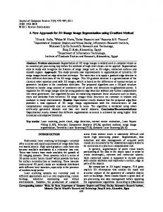
I. I NTRODUCTION Preserving cultural heritage and historic sites is an important problem. The advent of new digital 3D scanning devices has provided new means to preserve these sites digitally, and to preserve the historic record by building geometric and photorealistic 3D models. A recent international conference (Virtual and Augmented Architecture ‘01 [6]) has highlighted the need for simple and automatic methods to create rich models of historic environments. A number of other projects have addressed this and similar problems including [14], [8], [5], [4], [3]. This paper discusses new methods we have developed to recover complete geometric and photometric models of large sites and to automate this process. In particular, we discuss new methods for data abstraction and compression through segmentation, 3D to 3D registration (both coarse and fine), and 2D to 3D texture mapping of the models with imagery. The testbed for our methods is the Cathedral of Ste. Pierre in Beauvais France 2 (See fig. 1), a unique and still used church which is a prime example of high gothic architecture [9]. A team of Columbia University architectural historians, computer scientists, and engineers has begun to study the fragile structure of the tallest medieval cathedral in France. The thirteenth-century Gothic cathedral at Beauvais collapsed three times in the Middle Ages and continues to pose problems for its long-term survival. Our group is creating a highly accurate threedimensional model based on laser scans of the interior 1 This work was supported in part by NSF grant IIS-01-21239, CUNY Institute of Software Design and Development, and the Samuel Kress Foundation. We also wish to thank Prof. Stephen Murray for introducing us to the site at Beauvais. 2 Images are best viewed in color
and exterior of the building. This information will be used to examine the weaknesses in the building and propose remedies; visualize how the building looked when it was first built; and to serve as the basis for a new collaborative way of teaching about historic sites both in the classroom and on the Internet. The building is included on the World Monuments Fund’s Most Endangered List. Although the cathedral survived the heavy incendiary bombing that destroyed much of Beauvais during World War II, the structure is as dangerous as it is glorious, being at risk from flaws in its original design, compounded by differential settlement and with stresses placed on its flying buttresses from gale force winds off the English Channel. The winds cause the buttresses to oscillate and already weakened roof timbers to shift. Between the 1950s and 1980s numerous critical iron ties were removed from the choir buttresses in a damaging experiment. A temporary tie-and-brace system installed in the 1990s may have made the cathedral too rigid, increasing rather than decreasing stresses upon it. There continues to be a lack of consensus on how to conserve the essential visual and structural integrity of this Gothic wonder. With its fiveaisled choir intersected by a towered transept and its great height (keystone 152.5 feet above the pavement), Beauvais Cathedral, commissioned in 1225 by Bishop Milon de Nanteuil, provides an extreme expression of the Gothic enterprise. II. DATA ACQUISITION The surveying process involved capturing range and intensity data. On site work started in June 2001 using a Cyrax 2400 scanner. The whole interior and 1/3 of the exterior were surveyed, but due to technical problems, the scanning process was aborted and resumed in June 2002, this time with a new Cyrax 2500 scanner. Over 200 range images were acquired, 120 interior and 100 exterior scans, most of them sampled at 1000 by 1000 points. Intensity images were captured by a 5 megapixel digital camera, which was freely placed. The scanner uses a time-of-flight laser technology to measure the distance to points on an object. Data from the scanner comprises point clouds, each point comprising four coordinates, (x, y, z) and a value representing the amplitude of the laser light reflected back to the scanner. The amplitude is dependent on the reflectance of the material and the surface orientation.
III. R EGISTRATION OF R ANGE S CANS In order to acquire data describing an entire structure, such as the Beauvais Cathedral, multiple scans must be taken from different locations which must be registered together correctly. Although the point clouds may be registered manually, it is very time consuming and errorprone. Manually visualizing millions of small points and matching them is quite imprecise and difficult as the number of scans increases. When possible, it is a common practice to use specially designed targets/fiducials to help during the registration phase. In our case, however, it was almost impossible to place targets higher than 2.5 mts above the ground, requiring us to develop an automatic registration method. Our registration method is a three step process. The first step is an automatic pairwise registration between two overlapping scans. The pairwise registration matches 3-D line segments extracted from overlapping range scans to compute the correct transformation. The second step is a global registration step that tries to align all the scans together using overlapping pairs. The third step is a multiimage simultaneous ICP algorithm [2] that does the final fine registration of the entire data set. We describe each of these processes below.
Fig. 1.
B. Pairwise Registration Left Scan S1
Right Scan S2
Plane and Line Extraction
Plane and Line Extraction
SEGMENTATION Left lines l Left planes Pl
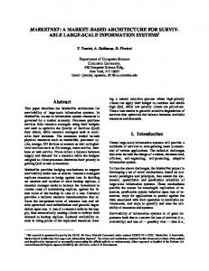
A. Segmenting the Scans Our previously developed range segmentation algorithm [12], [13] automatically extracts planar regions and linear features at the areas of intersection of neighboring planar structures. Thus, a 3–D range scan is converted to a set of bounded planes and a set of finite lines (see Fig. 3). The extracted 3–D intersection lines are very accurate because their orientation and length depends on all the points of both planes that intersect. After the segmentation step, the following elements are extracted from the point clouds: planar regions P, outer and inner borders of those planar regions B out and Bin , outer and inner 3D border lines L in and Lout (defining the borders of the planar regions), and 3D lines of intersection I at the boolean intersection of the planar regions. Border lines are represented by their two endpoints (pstart , pend ), and by the plane Π on which they lie. That is, each border line has an associated line direction, and an associated supporting plane Π. In more detail, we represent each border line as a tuple (pstart , pend , pid , n, psize ), where pid is a unique identifier of its supporting plane Π, n is the normal of Π, and psize is the size of Π. We estimate the size of the planes by using their number of range points on the plane, the computed distance of the plane from the origin of the coordinate system and by the plane normal. The additional information associated with each line greatly helps the automated registration.
Beauvais Cathedral.
Right lines r Right planes Pr
PREPROCESSING VALID LINE AND PLANE PAIRS STAGE 1 Get next line pair (l1,r1) Rotation computation (R) Translation estimation (Ts) NO MORE TAGE 1 PAIRS
Reject line pairs incompatible with R SUCCESS
NO MORE STAGE 2 PAIRS
STAGE 2 Get next line pair (l2,r2) Verify compatibility with Ts Translation computation (T) Verify T SUCCESS STAGE 3
STAGE 4 Refine best (R,T)
Grade transform (R,T) Keep best transform so far
FINAL TRANSFORM
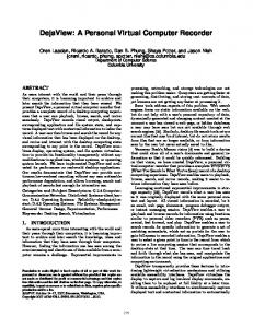
Fig. 2.
Automatic registration between a pair of overlapping scans.
In this section we describe the automatic registration between a pair of overlapping range scans S 1 and S2 . We are solving for the rotation matrix R and translation vector T = [T x , Ty , Tz ]T that place the two scans in the same coordinate system 3 . The flowchart of the algorithm is shown in fig. 2. The features extracted by the segmentation algorithm are automatically matched and verified in order to compute the best rigid transformation between the two scans. The input to the algorithm is a set of lines with associated planes (see section III3 If a point p is expressed in the coordinate system of scan S , then 1 p� = Rp + T is the same point expressed in the coordinate system of scan S2 .
Fig. 3. Top: Segmented regions from point cloud. Bottom: 14 segmented, automatically registered scans.
A). Let’s call scan S1 the left scan, and scan S 2 the right scan. Each left line l is represented with the tuple (pstart , pend , pid , n, psize ), and each right line r with the tuple (p�start , p�end , p�id , n� , p�size ) (see section III-A). The algorithm works as follows. 1) At a preprocessing step pairs whose ratios of lengths and plane sizes psize , p�size is smaller than a threshold are filtered out. Even though the overlapping parts of the two scans are not acquired identically by the scanner (because of occlusion and noise), the data was accurate enough for the extracted matching lines to have similar lengths and positions and matching planes similar sizes. After some experimentation we were able to find thresholds that worked on all pairs of scans, giving results of similar quality. 2) Sort all possible pairs of left and right lines (l, r) in lexicographic order. 3) STAGE 1: Get the next not visited pair of lines (l1 , r1 ). Compute the rotation matrix R, and an estimation of the translation T est assuming the match (l1 , r1 ).
4) Apply the computed rotation R to all pairs (l, r) with l > l1 . Reject all line pairs whose directions and associated plane normals do not match after the rotation. If the number of remaining matches is less than the current maximum number of matches, go to STAGE 1. Otherwise accept the match between lines (l1 , r1 ) and their associated planes. 5) STAGE 2: Get the next pair (l 2 , r2 ) from the remaining pairs of lines. Reject the match if it is not compatible with the estimated translation T est . Compute an exact translation T from the two pairs (l 1 , r1 ) and (l2 , r2 ). Verify that the two line pairs and their associated plane normals are in correspondence after the translation T is applied. Accept (l 2 , r2 ) as the second match. 6) STAGE 3: Grade the computed transformation (R, T ), by transforming all valid left lines to the coordinate system of the right scan, and counting the absolute number of valid pairs that are in correspondence. Go to STAGE 1. 7) STAGE 4: After all possible combinations of valid pairs have been exhausted, the best computed transform (R, T ) is recomputed by using all matched lines. The pairwise registration algorithm efficiently computes the best rigid transformation (R, T ) between a pair of overlapping scans S 1 and S2 . This transformation has an associated grade g(R, T ) that equals the total number of line matches after the transformation is applied. Note that the grade is zero if there is no overlap between the scans. C. Global Registration In a typical scanning session tens or hundreds of range scans need to be registered. Calculating all possible pairwise registrations is impractical because it leads to a combinatorial explosion. In our system, the user is providing a list of overlapping pairs of scans. All pairwise transformations are computed (see section III-B). Then, one of the scans is chosen to be the anchor scan S a . Finally, all other scans S are registered with respect to the anchor Sa . In the final step, we have the ability to reject paths of pairwise transformation that contain registrations of lower confidence. In more detail, the rigid transformations (R i , Ti ) and their associated grades g(R i , Ti ) are computed between each pair of overlapping scans. In this manner a weighted undirected graph is constructed. The nodes of the graph are the individual scans, and the edges are the transformations between scans. Finally the grades g(R i , Ti ) are the weights associated with each edge. More than one path of pairwise transformations can exist between a scan S and the anchor S a . Our system uses a Dijkstra-type algorithm in order to compute the most robust transformation path from S to Sa . If p1 and p2 are two different paths from
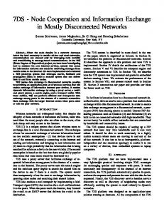
S to Sa , then p1 is more robust than p 2 , if the cheapest edge on p1 has a larger weight than the cheapest edge of p2 . This is the case because the cheapest edge on the path corresponds to the pairwise transformation of lowest confidence (the smaller the weight the smaller the overlap between scans). In this manner, our algorithm utilizes all possible paths of pairwise registrations between S and S a in order to find the path of maximum confidence. This strategy can reject weak overlaps between scans that could affect the quality of the global registration between scans. Fig. 3 shows a partial registration of 14 segmented scans, with scanner coordinate axes shown as well. D. Simultaneous Registration of Multiple Range Images Once the range images are registered using the automatic method above, a refinement of the basic ICP algorithm to simultaneous registration of multiple range images is used to provide the final registration. This method is an extension of the method proposed by Nishino and Ikeuchi [10]. Their work extends the basic pairwise ICP algorithm to simultaneous registration of multiple range images. An error function is designed to be minimized globally against all range images. The error function utilizes an M-estimator that robustly rejects the outliers and can be minimized efficiently through the conjugate gradient search framework. To speed up the registration process, a k-d tree structure is employed so that the search time for the matched point is reduced. One major drawback of the point-to-point approach is, if only the point-to-point geometric distance is used, its inability of finding the best match point in the sliding direction. Additional information to suggest better matches is required. For this purpose, the laser reflectance strength value (referred to as RSV) is used. To find a best match point of a model point, multiple closest points in a K-D tree are searched. Then the RSV distance (to the model point) for each of them is evaluated to get the closest point. Once correspondences are made, least-squares is typically used to find the correct transformation matrices for the data points. However, in the presence of outliers, leastsquares can be unstable. Accordingly, an M-estimator is used to weight the data points. The procedure is iterative, using a conjugate-gradient search to find the minimum. Figure 4 shows the reduction of error vs. iteration for a known test data set. The data set of Beauvais Cathedral contains over 100 scans, and it requires significant computational resources and time to register these scans with full resolution; therefore, those scans are sub-sampled down to 1/25 of their original resolution. Using this method the error metric is reduced from 0.27 to 0.13. Figure 4 also shows the results of applying the algorithm on 2 scans that have been coarsely registered. The column, which is misaligned initially, is correctly aligned after the
procedure. The resulting model is very large, made up of data from all the scans, and visualizing the entire model can be difficult. Fig. 5 show the resulting model from a number of views. For these models, 120 scans were registered on the inside of the cathedral, and 47 on the outside. A 3-D video fly-through animation of the model is available at the website: www.cs.columbia.edu/˜allen/BEAUVAIS. IV. T EXTURE MAPPING The range data allowed us to build a geometrically correct model. For photorealistic results we mapped intensity images to the polygon meshes. The input to the texture mapping stage is a point cloud, a mesh corresponding to the point cloud, and a 2D image. A user manually selects a set of corresponding points from the point cloud and the 2D image which are used to compute a projection matrix P that transforms world coordinates to image coordinates. The method for computing P is described in [7]. Let (Xi , xi ) be a pair of 3D and 2D homogeneous point correspondences, with X i and xi of the form (Xi , Yi , Zi , Wi ) and (xi , yi , wi ) respectively. Each pair provides the following two equations, 1 � � P T T T 0 −wi Xi yi Xi P2 = 0, wi Xi T 0T −xi Xi T P3 where each P i is a row of P . By stacking up the equations derived from a set of n pairs, a 2n x 12 matrix A is obtained. The solution vector p of the set of equations Ap = 0 contains the entries of the matrix P . At least 6 point correspondences are required to obtain a unique solution. In practice, an overdetermined system is used, which we solve using the SVD decomposition of matrix A. Prior to solving the system of equations, both 3D and 2D points are normalized to improve data accuracy [7]. This normalization consists of a translation and scaling step. Both 2D and 3D points are translated so that their centroid is at the origin. Both 2D and 3D points are then scaled so that√their RMS √ (root-mean-squared) distance to the center is 2 and 3 respectively. Once the projection matrix P is obtained an occlusion function V (P, T i ) → 0, 1 where each T i is a mesh triangle is computed. The function evaluates to 1 when T i is visible from the camera described by P and 0 otherwise. At this point the mesh is textured by calculating the texture coordinates of every visible triangle. The matrix P can also be computed from 3D and 2D line correspondence or a mixture of both, points and lines. We are currently working on computing P using line correspondences so that we can later make this process automatic following the ideas of the range to range registration described before. Figure 5 shows a textured mesh of the cathedral from a number of views.
Fig. 4.
Left: ICP Convergence. Right: Before and after fine registration. Note column misalignment has been corrected.
V. C ONCLUSIONS AND F UTURE W ORK We have developed methods that can address the problem of building more and more complex 3D models of large sites. The methods we are developing can automate the registration process and significantly reduce the manual effort associated with registering large data sets. Due to the complexity of these sites, building 3-D models is time consuming and difficult, usually involving much manual effort. Texture mapping can also be automated in a similar way using distinguishable features on 3D and 2D images to create a texture map. We are developing automatic feature selection algorithms to create these maps. In addition, texture mapping is currently done with single 2D images. We are working to incorporate multiple overlapping images to completely fill in a texture map. We also are implementing our own sensor planning algorithms to reduce the number of scans [11]. We have mounted the scanner on our AVENUE mobile robot [1]. We can then link our sensor planning algorithms to our mobile robot path planning algorithms, and automatically acquire scans of large sites. VI. REFERENCES [1] P. K. Allen, I. Stamos, A. Gueorguiev, E. Gold, and P. Blaer. Avenue: Automated site modeling in urban environments. In 3rd Int. Conference on Digital Imaging and Modeling, Quebec City, pages 357–364, May 2001. [2] P. J. Besl and N. D. Mckay. A method for registration of 3–D shapes. IEEE Transactions on PAMI, 14(2), Feb. 1992. [3] P. E. Debevec, C. J. Taylor, and J. Malik. Modeling and rendering architecure from photographs: A hybrid geometry-based and image-based approach. In SIGGRAPH, 1996. [4] P. Dias, V. Sequeira, J. M. Goncalves, , and F. Vaz. Combining intensity and range images for 3d architectural modelling. In International Symposium
[5]
[6]
[7]
[8]
[9] [10]
[11]
[12]
[13]
[14]
on Virtual and Augmented Architecture. SpringerVerlag, 2001. S. F. El-Hakim, P. Boulanger, F. Blais, and J.-A. Beraldin. A system for indoor 3–D mapping and virtual environments. In Videometrics V, July 1997. R. Fisher, K. Dawson-Howe, and C. O’Sullivan. International Symposium on Virtual and Augmented Architecture, Trinity College Dublin. SpringerVerlag, 2001. R. Hartley and A. Zisserman. Multiple View Geometry in Computer Vision. Cambridge University Press, 2000. M. Levoy, K. Pulli, B. Curless, S. Rusinkiewicz, D. Koller, L. Pereira, M. Ginzton, S. Anderson, J. Davis, J. Ginsberg, J. Shade, and D. Fulk. The Digital Michelangelo Project: 3D scanning of large statues. In SIGGRAPH, 2000. S. Murray. Beauvais Cathedral, architecture of transcendence. Princeton University Press, 1989. K. Nishino. and K. Ikeuchi. Robust simultaneous registration of multiple range images. In The 5th Asian Conference on Computer Vision, 2002, pages 454–461, January 2002. M. K. Reed and P. K. Allen. Constraint based sensor planning. IEEE Trans. on PAMI, 22(12):1460–1467, 2000. I. Stamos and P. K. Allen. 3-D model construction using range and image data. In Computer Vision & Pattern Recognition Conf. (CVPR), pages 531–536, June 2000. I. Stamos and P. K. Allen. Geometry and texture recovery of scenes of large scale. Computer Vision and Image Understanding(CVIU), in press, 2002. The piet´a project. http://www.research.ibm.com/pieta.
Fig. 5. Row 1: Exterior model, 47 registered scans. Row 2-3: Interior model (viewed from outside and inside), 120 registered scans. Row 4: Texture mapped views of the model.