4×4-Bit Array Two Phase Clocked Adiabatic Static CMOS Logic Multiplier with New XOR Nazrul Anuar
Yasuhiro Takahashi and Toshikazu Sekine
Graduate School of Engineering Gifu University, 1-1 Yanagido, Gifu-shi 501–1193 Japan Email:
[email protected]
Department of Electrical and Electronic Engineering Gifu University, 1-1 Yanagido, Gifu-shi 501–1193 Japan Email:{yasut, sekine}@gifu-u.ac.jp
Abstract— This paper presents the simulation results of a 4ˆ4-bit array two phase clocked adiabatic static CMOS logic (2PASCL) multiplier using 0.18 —m standard CMOS technology. We also propose a new design of 2PASCL XOR which reduces the number of transistors as well as the power consumption. Analytical method to compare the lower current flow in adiabatic circuit is also presented. At transition frequencies of 1 to 100 MHz, 4ˆ4-bit array 2PASCL multiplier shows a maximum of 55% reduction in power dissipation to that of a static CMOS. The results indicate that 2PASCL technology can be advantageously applied to low power digital devices operated at low frequencies, such as radio-frequency identifications (RFIDs), smart cards, and sensors.
I. I NTRODUCTION In recent years, various energy recovery circuits with adiabatic circuitry for ultra-low power implementation have been presented [1]–[15]. Adiabatic charging [1] is a principle where all charge transfer occurs without generating heat. The energy advantage can be understood by assuming a constant current 2 source that delivers the charge CL Vdd over a time period T . The dissipation through the channel resistance R is then 2 L Ediss = ( RC T )CL Vdd [2]. Theoretically, it is possible to reduce the dissipation to an arbitrary degree by increasing the switching time to ever-larger values. Conventional adiabatic logic circuits [1]–[10] that have been proposed shows a much less power dissipation compared with static CMOS circuit. For instance, at 10 MHz clock input, efficient charge recovery logic (ECRL) [10] dissipates only 16% of the energy of static CMOS logic in a chain inverter application. However, most of these circuits require multiphase power clocks. Several problems, such as a complicated clock design and an increase of energy dissipation due to the power clocks occur. Furthermore, for a single and a two phase clock circuits, diode-based families [4]–[9] have several disadvantages such as output amplitude degradation and the energy dissipation across the diodes in the charging path [16]. At the earlier stage of the 2PASCL [17], we have designed, simulated, and compared the power consumption of 2PASCL NOT, 2NAND, 2XOR, and 2NOR to CMOS topology. We have also discussed the pros and cons of 2PASCL compared to other proposed adiabatic logics that are easily derived from CMOS in [16]. 2PASCL fundamental logics significantly exhibit a lower power dissipation [18]–[19].
In this paper, we simulate a 4×4-bit array 2PASCL multiplier utilizing 0.18 µm standard CMOS technology using a new 2PASCL 2XOR. Analysis on the low-power dissipation in adiabatic charging and discharging using constant voltage value and ramp-wave voltage is also carried out. 2PASCL technology can be advantageously applied to low power digital devices operated at low frequencies, such as radio-frequency identifications (RFIDs), smart cards, and sensors. The remainder of the paper is organized as follows. Section II describes the adiabatic charging theory. In Section III, we briefly explain the circuit operation of 2PASCL. In Section IV, the simulation results of 2XOR and 4×4-bit array 2PASCL multiplier are presented. Section V includes concluding remarks and future work. II. A DIABATIC C HARGING Adiabatic charging is the technique in which charge moves from power supply to the load capacitance by using slow and constant-current charging. This can be modeled by analytically deriving the current ip (current flow through pMOS) of instant Vdd and ramp wave from Vφ , the voltage supply as shown in Fig. 1. The ip equation can be derived as below; Vφ (t)
=
ip (t)
=
vy (0 )
=
Rp ip (t) + vy (t), dvy (t) , C dt 0,
(1) (2) (3)
for constant Vdd ; Vφ (t)
=
Vdd ,
(4)
t Vdd − RC e , Rp
(5)
Vdd t [u(t) − u(t − τ )] + Vdd [u(t − τ )] , τ
(6)
therefore, ip (t)
=
for ramp-wave voltage; Vφ (t)
therefore,
=
Vdd (Instant and ramp-wave)
Vφ
2
VX [V]
Vφ (t)
Vφ ip (t)
Vdd
1 0 2
Rp (b) Instant
vy(t)
(τ=0)
VX
VY
Vφ (t)
CL
Vφ− 2
VY [V]
t
(c) Ramp-wave
Energy [fJ]
(a) Equivalent circuit of CMOS pull-up network
Vφ 1 0
CL
Vdd
τ
Fig. 1.
[V]
t
CMOS equivalent circuit during pull-up network.
1
0 40 20
Ei
0
-20 0
vy(0-) = Vdd vy in Rn
vφ
vφ
C 0
(a) CMOS pulldown network
(b) Instant (τ∼0)
0
τ (c) Ramp-wave
20
Time [ns]
E2
30
(b)
Fig. 3. (a) 2PASCL inverter circuit. (b) Waveforms from the simulation, transition frequency X=50 MHz, Vφ = Vφ = 100 MHz.
vφ
t
10
(a)
Vdd
Vdd
Er
E1
Vφ
Energy dissipation per cycle
t
TABLE I 2PASCL NOT LOGIC CIRCUIT OPERATION
Fig. 2.
ip (t)
CMOS equivalent circuit during pull-down network.
−t t−τ CVdd CVdd (1 − e CRp ) − (1 − e CRp )u(t − τ ), (7) τ τ
=
where, u(t) denotes Heaviside’s unit function. From Eq. (7), it is clearly seen that ip can be reduced by increasing τ , the time for Vφ to change from 0 to Vdd . As shown in the equivalent circuit of CMOS during pulldown network as in Fig. 2, in can be derived as below; 0
=
in (t)
=
vy (0 )
=
Rn in (t) + vy (t), dvy (t) −C , dt Vdd .
=
therefore, h
in (t) = Vdd Rn C 2 +
Vdd −
Vdd t [u(t) − u(t − τ )] , τ
(9)
pMOS
nMOS
Y
LO HI
ON OFF
OFF ON
HI LO
Hold
HI
OFF
ON
No Transition
clocks and the output. The power supply clocks used in 2PASCL are Vφ and Vφ , where Vφ
=
Vdd 3 sin(ωo t + θ) + Vdd , 4 4
(13)
Vφ
=
−
Vdd 1 sin(ωo t + θ) + Vdd . 4 4
(14)
(10)
(11)
t−τ 1 −(CRn + t − e Rn C (τ + CRn )) τ i i
h
Y−1
Evaluation
(8)
for adiabatic discharging, Vφ (t)
Mode
t
u(t − τ ) + τ (−1 + e CRn (1 − CRn ) + t) C . (12)
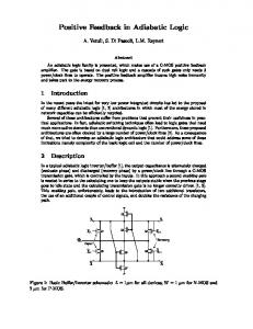
From Eq. (12), it is also demonstrated that in can be reduced by increasing τ , the time for Vφ to change from Vdd to 0. III. 2PASCL A. Circuit Operation Figure 3 shows a circuit diagram and waveforms illustrating the operation of the 2PASCL inverter [17]. Waveforms of Fig. 3 (b) are the input, split-level sinusoidal power supply
On the last graph of Fig. 3(b), the instantaneous energy dissipation is presented. In energy-recovery circuits, based on the energy conservation law, energy dissipated is equal to the total of energy injected to the circuit, Ei and the energy received back from the circuit capacitance, Er . This is shown in this energy dissipation graph. The circuit operation is divided into two phases, evaluation and hold. In the evaluation phase, Vφ swings up and Vφ swings down. On the other hand, in the hold phase, Vφ swings up and Vφ swings down. Let us consider the inverter logic circuit demonstrated in Fig. 3. The operation of the 2PASCL inverter can be summarized as in Table I. The number of dynamic switching transition occuring during the operation of the 2PASCL circuit decreases since the charging/discharging of the circuit nodes does not necessarily occur during every clock cycle. Hence, node switching activities are suppressed to a significant extent and consequently, energy dissipation is also reduced. One of the advantages of the 2PASCL circuit is that it can be made to behave like a static logic circuit.
Vφ
2
a [V]
a
Y CL
1
0
b [V]
2
Vφ
1
Vphi- [V] Vphi [V]
0 2
1
0
b
Fig. 4.
Y [V]
2
Old 2PASCL 2XOR schematic.
1
0 0
2
4
6
8
Vφ
10
t [s] [×10-8]
2
a [V]
a
1
0
b
b [V]
2
Y CL
1
Vphi- [V] Vphi [V]
0 2
1
Vφ
0 2
New design of 2PASCL 2XOR schematic.
Y [V]
Fig. 5.
1
0 0
2
4
6
8
10
t [s] [×10-8]
IV. S IMULATION R ESULTS A. 2PASCL 2XOR comparison Table II describes the details of the new 2PASCL 2XOR as compared to the previous design. Figure 4 shows the schematic of previous 2PASCL 2XOR logic circuit, where a and b are the inputs, Vφ and Vφ are the the power supply clocks and Y is the output. A new 2PASCL 2XOR which has less transistors than the previous schematic is shown in Fig. 5. We derived the 2XOR CMOS presented by Wang et al. [21] to the new 2PASCL 2XOR by adding the nMOS and pMOS diodes only at the NOT logic of the original 2XOR. Then, split level sinusoidal power clocks are supplied as shown in Fig. 3. As in Table II, the number of transistors have been reduced from 15 to 8 in 2XOR. As MOSFETs in both 2PASCL and CMOS can be modeled as an ideal switch in series is included with a TABLE II
Fig. 6. Output waveforms of (top) the old 2PASCL 2XOR and (bottom) the new 2PASCL 2XOR schematic.
resistor R in order to represent the sum of the effective channel resistance of the switch and the interconnect resistance. We reduced the total resistance by minimizing the number of transistors, consequently reducing the power dissipation. In Fig. 6, we describe the simulation results of each schematic design. By comparing these two results at 50 MHz transition frequency, much better output waveforms generated by the schematic shown in Fig. 5 are observed. This is due to the shorter transmission path, consequently reduced signal degradation. Therefore, in the simulation, the power dissipated is calculated by integrating the product of voltage and current divided by the period of the primary input signal, T as follows:
D ETAILS OF 2XOR LOGIC
1 P = T No. of transistors W/L [µm] W/L (nMOS diode) [µm] Vφ , Vφ CL
Old 2PASCL 2XOR
New 2PASCL 2XOR
15
8
0.6/0.18
0.6/0.18
40/40
40/40
0.9 V, 0.9 V
0.9 V, 0.9 V
0.01 pF
0.01 pF
Z
0
T
n X i=1
!
(Vpi × Ipi ) dt,
(15)
where Vp , the power supply voltage; Ip , the power supply current; and n, is the number of power supplies [8]. In Fig. 7, we compare the power dissipation of old and new design from 1 to 100 MHz transition frequencies. An average of half of the power dissipation can be saved by the new 2PASCL 2XOR design.
P0 [V] A3,B3 A2,B2 A1,B1 AO,BO P1
old 2PASCL XOR
new 2PASCL XOR
P2
10-1
P4
P3
Power dissipation [µW]
100
107
108
P5
10-2 6 10
P7
P6
Transition frequency [Hz] Fig. 7. Power dissipation comparison of the old and new design of 2PASCL 2XOR. a0
p0
b0 a0 a1 b0 a2
b1
200
400
Time [ns]
600
800
Fig. 9. Output waveforms of 4×4-bit array 2PASCL multiplier at 10 MHz transition frequency from the simulation.
p1
HA
a1
2 1 0 2 1 0 2 1 0 2 1 0 2 1 0 2 1 0 2 1 0 2 1 0 2 1 0 2 1 0 2 1 0 2 1 0 0
a0
b1 HA
b2
FA
a1 b2
FA
p2
a2 a3
b1 HA
a0 b3
p3 FA
b0 a1 b3
a2 a3
b2
FA
FA
HA
p4
FA
FA
p5
FA
p6
b1
a3
a2 b3
103
4x4-bit array CMOS Multiplier
102
b2 a3
Power dissipation [µW]
b0
4x4-bit array 2PASCL Multiplier
b3 p7
Fig. 8.
Block diagram of 4×4-bit array multiplier.
101 106
107
108
Transition frequency [Hz]
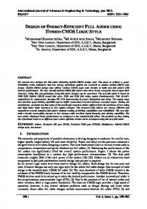
B. 4×4-bit array 2PASCL multiplier Figure 8 shows the diagram of 4×4-bit array multiplier which consists of sixteen ANDs, six full adders and four half adders logics. Load capacitance ranging from 0.01 to 0.1 pF are set at all outputs (p0 to p7 ). For fabrication, 2PASCL Dflipflops [17] are also used to capture all the 8-bit signals at the moment the clock is in HI state. In Fig. 9, we demonstrate the input and output waveforms of 10 MHz transition frequency 4×4-bit array 2PASCL multiplier. From these results, we confirm that our 4×4-bit array 2PASCL multiplier is functioning correctly. However, the signal glitch occurs at output p2 to p4 . Figure 10 shows the power dissipation of 2PASCL multipliers which are about 55% less than CMOS multipliers of the same transistor size W/L of 0.6/0.18µ. However, from our simulation results, 4×4-bit array 2PASCL multiplier only shows a good logic functionality of up to 200 MHz transition frequency. We observe some signal degradations for transition frequency of more than 200 MHz. This is due to the charging time T which is much slower than conventional CMOS. T is
Fig. 10. Power dissipation comparison of 4×4-bit array 2PASCL multiplier and 4×4-bit array CMOS multiplier.
also proportional to RCL i.e. the longer the path, the larger T is needed. These input frequencies are adequate for the applications mentioned in Section I. V. C ONCLUSION In this paper we designed and simulated a 4×4-bit array two-phase clocked adiabatic CMOS logic (2PASCL) multiplier circuit using a new 2XOR. The simulation results show that power consumption in the 2PASCL multiplier is considerably less than that in a CMOS. For instance, when the input frequency is simulated from 1 to 100 MHz, the 2PASCL multiplier logic dissipates minimally as only half of the power dissipated by a static CMOS logic circuit. We believe that the proposed adiabatic logic circuit is advantageous for ultra lowenergy computing applications. As for our future work, we will further evaluate the cause of the signal glitches in 2PASCL.
R EFERENCES [1] W.C. Athas, L.J. Svensson, J.G. Koller, N. Tzartzains, and E. Y-C. Chou, “Low-power digital systems based on adiabatic-switching principles,” IEEE Trans. Very Large Scale Integration (VLSI) Syst., vol. 2, no. 4, pp. 398–407, Dec. 1994. [2] C.L. Seitz, A.H. Frey, S. Mattison, S.D. Rabin,D.A. Speck, and J.L.A. van de Snepscheut, “Hot-clock NMOS,” Proc. 1985 Chapel Hill Conf. VLSI, pp. 1–17, 1985. [3] A. Kramer, J.S. Denker, S.C. Avery, A.G. Dickinson, and T.R. Wik, “Adiabatic Computing with the 2N-2N2D logic family,” Proc. IEEE Symp. VLSI Circuits Dig. Tech. Papers, pp. 25–26, Jun. 1994. [4] A.G. Dickinson and J.S. Denker, “Adiabatic dynamic logic,” IEEE J. Solid-States Circuits, vol. 30, no. 3, pp. 311–315, Mar. 1995. [5] K.T. Lau and F. Liu, “Improved adiabatic pseudo- domino logic,” Electron. Lett., vol. 33, no. 25, pp. 2113–2114, 1997. [6] K. Takahashi and M. Mizunuma, “Adiabatic dynamic CMOS logic circuit,” Electronics and Communications in Japan Part II, vol. 83, no. 5, pp. 50–58, Apr. 2000 [IEICE Trans. Electron., vol. J81-CII, no. 10, pp. 810–817, Oct. 1998]. [7] Y. Ye, and K. Roy, “QSERL: Quasi-static energy recovery logic,” IEEE J. Solid-States Circuits., vol. 36, no. 2, pp. 239–248, Feb. 2001. [8] Y. Takahashi, Y. Fukuta, T. Sekine, and M. Yokoyama, “2PADCL: Two phase drive adiabatic dynamic CMOS logic,” Proc. IEEE APCCAS, pp. 1486–1489, Dec. 2006. [9] C. Siyong, et al, “Analysis and design of an efficient irreversible energy recovery logic in 0.18µm CMOS,” IEEE Trans. Circuits and Syst., vol. 55, no. 9, pp. 2595–2607, Oct. 2008. [10] Y. Moon and D.K. Jeong, “An efficient charge recovery logic circuit,” IEEE J. Solid-States Circuits, vol. 31, no. 4, pp. 514–522, Apr. 1996. [11] V.I. Starosel‘skii, “Reversible logic,” Mikroelektronika, vol. 28, no. 3, pp. 213–222, 1999. [12] K.A. Valiev and V.I. Starosel‘skii, “A model and properties of a thermodynamically reversible logic gate,” Mikroelektronika, vol. 29, no. 2, pp. 83–98, 2000. [13] J. Marjonen, and M. Aberg, “A single clocked adiabatic static logic: a proposal for digital low power applications,” J. VLSI Signal Processing, vol. 27, no. 27, pp. 253–268, Feb. 2001. [14] V.I. Starosel‘skii, “Adiabatic logic circuits: A review,” Russian Microelectronics, vol. 31, no. 1, pp. 37–58, 2002. [15] S. Kim, C.H. Ziesler, and M.C. Papaefthymiou, “Charge-recovery computing on silicon,” IEEE Trans. Computers, vol. 54, no. 6, pp. 651–659, Jun. 2005. [16] N. Anuar, Y. Takahashi, and T. Sekine, “Two phase clocked adiabatic static CMOS logic and its logic family,” J. Semiconductor Technology and Science, vol. 10, no. 1, pp. 1–10, Mar. 2010. [17] N. Anuar, Y. Takahashi, and T. Sekine, “Two phase clocked adiabatic static CMOS logic,” Proc. IEEE SOC 2009, pp. 83–86, Oct. 2009. [18] N. Anuar, Y. Takahashi, and T. Sekine, “4-bit ripple carry adder of two-phase clocked adiabatic static CMOS logic,” Proc. IEEE TENCON 2009, THU4.P.16, Nov. 2009. [19] N. Anuar, Y. Takahashi, and T. Sekine, “Fundamental logics based on two phase clocked adiabatic static logic,” Proc. IEEE ICECS 2009, pp. 503–506, Dec. 2009. [20] N. Anuar, Y. Takahashi, and T. Sekine, “XOR evaluation for 4×4-bit array two-phase clocked adiabatic CMOS logic,” Proc. IEEE MWSCAS 2010 (In Press). [21] J.M. Wang, S.C. Fang, and W.S. Feng, “New efficient designs for XOR and XNOR functions on the transistor level,” IEEE J. Solid-States Circuits, vol. 29, no. 7, pp. 780–786, Jul. 1994.