University of Louisiana at Lafayette, Lafayette,. LA 70504. ABSTRACT. In an attempt to meet the low-power requirements of high performance portable signal ...
➠
➡ A DATA MERGING TECHNIQUE FOR HIGH-SPEED LOW-POWER MULTIPLY ACCUMULATE UNITS Ayman Fayed
Walid Elgharbawy, and Magdy Bayoumi
Intel Corporation RA3-250, 2501 NW 229th Avenue, Hillsboro, OR 97124
The Center for Advanced Computer Studies, University of Louisiana at Lafayette, Lafayette, LA 70504
ABSTRACT In an attempt to meet the low-power requirements of high performance portable signal processing VLSI systems, while maintaining a high operating speed, a new data merging architecture for high speed multiply accumulate units is proposed. The architecture can be applied on binary trees constructed using 4:2 compressor circuits. Increasing the speed of operation is achieved by taking advantage of the available free input lines of the compressor circuits, which result from the natural parallelogram shape of the generated partial products and using the bits of the accumulated value to fill in these gaps. This results in merging the accumulation operation within the multiplication process.
the multiplication circuit. Using tree architectures for the partial products reduction network represent an attractive solution that is frequently applied to speed up the multiplication process. Our contribution in this paper is introducing a merging technique for further speeding up the accumulation operation by merging it within the partial products reduction tree used for multiplication. This paper is organized as follows. Section 2 explains the problem statement and the proposed solution. In section 3, a proposed modified 4:2 compressor design and the proposed merging high-speed architecture are discussed. Delay and performance analysis are given in section 4. Sections 5 presents the architecture prototype and simulation results. Section 6 concludes the work done. 2. PROBLEM STATEMENT AND THE PROPOSED SOLUTION
1. INTRODUCTION The multiply accumulate unit represents one of the essential building blocks that is frequently used in digital signal processing applications. Applications such as Digital filtering, speech processing, video coding and CDMA require high processing speed while maintaining a low power consumption [1], [2] that allows embedding powerful processors in applications that are using portable power supplies. In order to improve the speed of this unit, there are two major bottlenecks that need to be considered. The first one is the partial products reduction network that is used in the multiplication block and the second one is the accumulator. Both of these stages require addition of large operands that involve long paths for carry propagation. The classical straightforward approach to build multiply accumulate units implements each part separately using individual functional blocks [1] and then cascade them to realize the complete operation. Another approach to speed up the operation implements both the multiplication and the accumulation operations within the same functional block by merging the accumulator with
0-7803-8484-9/04/$20.00 ©2004 IEEE
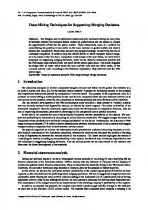
Using compressor circuits as the basic cell to construct the addition tree for partial products reduction in parallel multipliers has a great advantage since they introduce parallelism in adding the available operands instead of having them added sequentially which gives them a speed advantage [3]. However, a major disadvantage that occurs due to the natural parallelogram shape of the generated partial products is that some of the compressor circuits are not fully utilized since they don’t get data at all the available input lines. These unused inputs result in hardware inefficiency if they are filled with zeroes or design irregularity if they are modified to match the input pattern. The proposed architecture is based on fully utilizing the summation tree by feeding the accumulated data bits, as shown in figure 1, into the unused inputs of the 4:2 compressors such that the accumulation operation is merged within the multiplication circuit, which will save the cost of an additional accumulator. This can directly result in increasing the overall speed of the MAC operation. Power consumption and circuit area are saved as well. The concept of merged arithmetic was generally
V - 145
ICASSP 2004
➡
➡ introduced in [4] [5] to reduce the implementation cost and improve the processing speed. The main contribution of this work is to use the merging approach to enhance tree architecture for further speed improvement. A B N-bit N-bit PP-generation
A B
C D
Cout
Summation Network
Cin
Final Adder
Cout
Sum
(a)
A B
C D
2N+1 bit
C1in
Figure 1: Block diagram for the proposed merged architecture
3. THE PROPOSED ARCHITECTURE 3.1 The proposed modified 4:2 compressor design A definition for the compressor circuit is given in [6] as a combinational circuit that has K input lines (number of bits in column i) and 2 output lines representing the result of the compression. In addition, the compressor circuit has L carry in input lines entering the compressor at bit position i and generates the same number L of carry output lines at bit position i+1. Figure 2(a) [7] shows the circuit diagram for a regular 4:2 compressor. A modified design for the 4:2 compressor with a delay equivalent to 3 XOR gate units has been designed as shown in Figure 2(b). The designed circuit takes 4 input bits and a carry in of the same bit order and compresses them to generate a sum bit of the same order at the same position and two carry bits of higher order. The following formula can be proven to hold true for all inputs in order to ensure the functionality of the proposed circuit: 1 2 A � B � C � D � Cin1 � Cin2 Sum � (Cout � Cout � Cout )u2 3.2 The proposed merging architecture The proposed architecture is based on taking advantage of the free input lines of the available 4-2 compressors to implement the accumulation operation by feeding the bits of the accumulated operand into the summation tree, as shown in figure 1, instead of putting zeroes at these free input lines. Some minor enhancements are required for the existing hardware to accommodate the extra incoming bits of the accumulated operand. Without losing generality, the case of 8-bit multiplication is considered as a case study to present the proposed technique. Following the same approach, the same technique can be applied to larger word lengths.
C2in
C1out C2out
Cout
Sum
(b) Figure 2: (a) The conventional design for the 4:2 compressor. (b) The proposed design for the modified 4:2 compressor
Figure 3 shows the distribution of data among the tree with the bits of the accumulated operand distributed within the partial products bits. The compression tree consists of two stages. In the first stage, there are two blocks A and B that are used to reduce the number of partial products from 8 to 4. The bits of the accumulated operand, Z, are inserted within the tree as early as possible in those empty locations at the corresponding columns such that those 4:2 compressors are fully utilized. The bits Z0, Z1, Z2, Z5, Z6, Z7, Z8, Z9, Z10, Z12, Z13, Z14 are inserted in the first stage and the bits Z3, Z4, Z11, Z15 are inserted in the second stage. However, a problem occurs in the eighth column where the bit Z7 is supposed to be inserted. This bit results in increasing the number of bits in stage A at this column from 4 to 5 at the input of the compressor available at this column. To solve this problem, the new proposed design for a modified 4:2 compressor is used to handle this extra bit. The modified compressor circuit takes 4 input bits plus 2 carry in bits of the same order and generates a sum bit of the same order and three carry out signals of higher order. One of the carry out signals ‘Cout’ is transferred to the next column in the next stage while the other two carry out signals propagate horizontally to
V - 146
➡
➡ be fed into the compressor of the next column at the same stage. The decision of where to insert the bit Z7 determines the number of required modified 4:2 compressors. It is found that the best place to insert this bit is in the 8th column in block “A” of the first stage and use a modified 4:2 compressor at this location to accommodate the extra bit. The modified 4:2 compressor used will generate an additional carry out bit that is supposed to be fed to the next column. This in turn will require an additional modified 4:2 compressor in the 9th column at the first stage, which will also have an additional carry out. This carry out fits in the unused input of the 4:2 compressor available in the 10th column. This will end up with only two modified 4:2 compressors replacing the original regular 4:2 compressors of columns 8 and 9 in block “A” of the first stage with no delay penalty. A7 .…………...… A0 B7 .…………..… B0 Z8 Z9
Z0
Z10
Z1
1st Stage
Z2 Z12 Z13 Z14
Z5 Z6 Z7
2nd Stage
Z11 Z15
Z3 Z4
Final Adder Figure 3: Data bit distribution in the proposed MAC unit
Inserting the bit Z7 in later stages will result in the need of more modified 4:2 compressors in order to accommodate the extra carry bits generated. It’s worth noting that only two modified compressors are needed regardless of the word length of the operands. This technique results in improved utilization of the summation tree and eliminates the need for a separate cascaded accumulator circuit that would be used for the accumulation operation, which results in significant improvement in terms of the area used, Power consumed and speed of the overall MAC operation. 4. LOGIC DEPTH AND PERFORMANCE ANALYSIS The delay of the reduction tree is determined by the maximum logic depth of the circuit required to perform the compression operation on the column that has the maximum number of bits in the partial products matrix. In
order to determine the equivalent delay of the compression tree, we start with studying the critical paths of each of the compressor circuits used to build the tree in terms of the equivalent XOR circuit delay. The delays of the critical paths from inputs to outputs can be expressed as follows: Td ( A, B, C , D o Sum) 3d XOR Td (Cin o Sum) 1d XOR Td ( A, B, C , D o Cout ) 2d XOR For the modified 4:2 compressor circuit, the equivalent delay from input to output for each signal path can be expressed as follows: Td ( A, B, C , D o Sum) 3d XOR
Td (Cin1 , Cin2 o Sum)
2d XOR
1 out
2 Td ( A, B, C , D o C , Cout ) 1d XOR The actual delay values vary according to the technology and the logic style used to implement the circuit. Due to the natural parallelogram shape of the partial products matrix the number of partial product bits at the middle are more than those at the edges. This results in a non-uniform arrival profile of the bits generated by the reduction tree at the final adder stage and hence a nonuniform delay for the generation of these bits. The output of the tree takes the form of a single bit for position 0 and 2 bits of the same order for all the other positions. The largest logic depth in the tree occurs at column 8, in the case of an 8-bit MAC unit. This column creates a speed bottleneck in the reduction tree since the additional accumulated bit makes the total number of bits in this column equal to 9 instead of 8. The overall delay of the two stages will be equivalent to 6 XOR gate delay. To avoid potential delay due to horizontal carry propagation in the first stage of compressors at columns 8 and 9, the carry out signals of the modified design for the 4-2 compressor are fed to the adjacent compressor such that they don’t propagate through more than one other compressor. These carry out signals come out earlier than other outputs and are fed into advanced points at the next compressor such that the overall delay of the compression stage is balanced.
5. ARCHITECTURE PROTOTYPE AND SIMULATION RESULTS Two prototypes of an 8-bit MAC unit circuit are implemented using a bottom-up approach. Each building block is implemented and characterized individually and then used to construct the layout of the overall MAC unit. The first prototype is constructed using the cascaded approach and the second prototype is constructed using the proposed merged approach. A 0.18-micron CMOS technology is used to build the circuits. The layout is then extracted and a spice file is
V - 147
➡
➠ generated and used for simulation. A randomly generated input sequence is used to test different input combinations. The simulation results for the prototyped cells are presented in table 1. The measured values show that the proposed modified 4:2 compressor consumes 2% more power compared to the regular 4:2 compressor. This extra power consumption is corresponding to the additional functionality added to the circuit in order to accept a fifth input. The other penalty encountered at the circuit level occurred due to the 16% extra area needed to layout the modified 4:2 compressor circuit. No delay penalty occurred for the new design of the 4:2 compressor because it still has the same logic depth of the regular circuit. The power and the area penalties of the proposed 4:2 compressor didn’t affect the performance of the overall architecture because the proposed architecture needed only two of the modified compressor circuit. For the overall accumulation operation, the proposed merging architecture improved the power consumption by a factor of 19.5%. The improvement occurred due to the elimination of the separate accumulator. The speed is improved by a factor of 25%. Due to the elimination of the cascaded accumulator, 20% of the area is saved. Table 1: The characteristics of the building blocks and the 8-bit prototyped architectures
Regular 4:2 Compressor Modified 4:2 Compressor Carry Look Ahead Adder Cascaded MAC Merged MAC
Power (Watt)
Delay (Sec)
Area
1.52e-05
0.05e-09
18x24Ȝ2
1.58e-05
0.05e-09
18x30Ȝ2
1.03e-03
1.79e-09
320x1730Ȝ2
2.73e-03
1.57e-09
1800x2760Ȝ2
2.2e-03
1.26e-09
1540x2870Ȝ2
Table 2: Comparison results
Word Length Matrix height Compression Ratio Normalized Compression Ratio per XOR
Proposed Merged 8 16 9 17
Standard NonMerged [9] 8 16 8 16
Merged [8] 16 10
4.5
8.5
4
8
5
.75
.94
.66
.88
.714
Next the proposed architecture is analyzed and compared with both the standard 4:2 compression tree, where no merging techniques are applied, and the architecture presented in [8] for a 16-bit merged MAC unit. We used the compression ratio per XOR gate delay of the overall compression tree to measure the efficiency of each of the compared structures. Table 2 shows the comparison results with the other architectures, it’s clear that the proposed architecture is faster due to the insertion
of the accumulator bits into the unused inputs of the compression tree. 6. CONCLUSION A new architecture for high-speed design of MAC units is proposed. The architecture is based on applying a merging technique by inserting the accumulated operand into the unused inputs of the 4:2 compressor circuits in the partial products reduction network. Logic depth and delay analysis show that the proposed merging technique outperforms other merging techniques. 7. ACHNOWLEDGEMENT The authors acknowledge the support of the U.S. Department of Energy (DoE) EETAP program. 8. REFERENCES [1] Akilesh Parameswar, Hiroyuki Hara, “A Swing Restored Pass-Transistor Logic-Based MAC Circuit for Multimedia Applications,” IEEE Journal of Solid-State Circuits, Vol. 31, No. 6, June 1996. [2] N. Weste, and K. Eshraghian, Principles of the CMOS VLSI Design, A System Perspective. MA: AddisonWesley, 1993, reading. [3] Norio Ohkubo, Makoto Suzuki, “A 4.4 ns CMOS 54 x 54-b Multiplier Using Pass-Transistor Multiplexer,” IEEE Journal of Solid-State Circuits, Vol. 30, No. 3, Mar. 1995. [4] E. E. Swartzlander, Jr., “Merged Arithmetic,” IEEE Trans. Computers, Vol. C-29, pp. 946-950, 1980. [5] Fayez Elguibaly, “A Fast Parallel MAC Using The Modified Booth Algorithm,” IEEE Trans. on Circuits and Systems, VOL. 47, Issue 9, Sept. 2000 [6] Vojin G. Oklobdzija, and David Villeger, “Improving Multiplier Design by Using Improved Column Compression Tree and Optimized Final Adder in CMOS Technology,” IEEE Trans. on VLSI (VLSI Systems), Vol. 3, No. 2, pp. 292-301, June 1995. [7] Abdellatif Bellauar, and Mohamed I. Elmasry, LowPower Digital VLSI Design Circuits and Systems. Kluwar Academic Publishers, 1995, reading. [8] O. Kwon, K. Nowka and E. Swartzlander, “A 16-bit x 16-bit MAC Design Using Fast 5:2 Compressors,” at the 2000 IEEE International Conference on ApplicationSpecific Systems, Architectures and Processors, pp. 235243. [9] Stelling, P.F.; Oklobdzija, V.G., “Implementing multiply-accumulate operation in multiplication time,” in 1997 Proceedings 13th IEEE Symposium on Computer Arithmetic, pp. 99 –106.
V - 148