of a schematic graphical description and an additional constraint lan- guage is given. .... Here a diagram is used to de ne a graph class, i.e. the class of TGraphs representing a ... type hierarchies. Thus, when ..... kind: {norm, inj} limits: PI NI. PI.
A Declarative Approach to Graph Based Modeling Jurgen Ebert
Angelika Franzke
March 1994 Abstract The class of TGraphs, i.e. typed, attributed, and ordered directed graphs, is introduced as a general graph class for graph based modeling. TGraphs are suitable for a wide area of applications. A declarative approach to specifying subclasses of TGraphs by a combination of a schematic graphical description and an additional constraint language is given. The implementation of TGraphs by an appropriate software approach is described.
1 Introduction Modeling parts of the real world is a wide area of applications of graph theoretic concepts in practice. E.g. in the software design process the structure of the information to be kept and handled by the system is often describable by graphs. In order to describe which graphs are correct models and which are not, an approach to describing classes of graphs (graph languages) is necessary. Since graphs are to the same extent B expressive pictures, B formal models, and B e�cient data structures, a well-based approach to working with graphs is necessary, which covers all three aspects in a consistent manner. 1
In this paper, we introduce the class of TGraphs as a general graph class, which by being very general is suitable for a wide area of applications. We give a declarative approach to specifying subclasses of TGraphs by a combination of a schematic graphical description and an additional constraint language, and we show how TGraphs can be implemented appropriately. The declarative approach for describing graph classes, allows to check the correctness of a graph at any point of time. Here the constraints are forced by the graph module itself and not by the application program. The paper is organized as follows: In section 2 the class of TGraphs is described and a formal de nition is given1. Based on this de nition, section 3 introduces our approach to graph based modeling. We describe a speci cation language suitable to describe TGraph languages - i.e. subclasses of the general class - from a conceptual point of view, by using extended entityrelationship modeling in section 4 and an appropriate constraint description language in section 5. Section 6 certi es that the formal and conceptual descriptions may be implemented accordingly. Section 7 compares this work with related approaches, especially with graph grammar techniques. The approach is illustrated by an example chosen from a software engineering context, namely by a class of graphs that are models for state charts.
2 Basic De nitions Graph models are to a certain extent abstractions of an object-oriented view of the world. When using graphs, objects are usually represented by vertices, whereas relationships are modeled by edges. To enhance the modeling power of graphs, vertices and edges may be classi ed into di�erent types, and (depending on their types) they also may have attributes. To control graph traversal order in the context of graph algorithms an additional order can be put on the edges incident with a given vertex. Thus, a general class for modeling is the class of ordered directed graph with typed and attributed vertices and edges, called TGraphs in the following. An ordered directed graph is de ned by its set of vertices V and its set 1 Throughout the text, a Z-like notation is used. For an introduction to Z, the reader
is refered to [Diller 90] or [Spivey 92].
2
of edges E . The incidence relation between vertices and edges is a function �, which maps each vertex v 2 V to a sequence of all edges e 2 E that are incident to v . For each edge e in �(v ) also the direction of e with respect to v (e may be an ingoing or an outgoing edge) is speci ed. In order for G to be a correct graph, it has to be assured that every edge in E is mapped to exactly one vertex as an outgoing edge and to exactly one vertex as an ingoing edge. To model types, a universe of type identi ers is assumed. An attribute (instance) is de ned to be an ordered pair consisting of an attribute identi er and a corresponding attribute value. Then, a TGraph is an ordered directed graph extended by two functions. type assigns a type identi er to the vertices and edges, whereas value is an assignment of nite sets of attribute instances. Here, it is demanded that every vertex and every edge has exactly one type, whereas graph elements may or may not have attribute instances: UNIVERSE ::= vertex hhNii j edge hhNii VERTEX == ran vertex EDGE == ran edge DIR ::= in j out [ID ; VALUE ] typeID == ID attrID == ID attributeInstanceSet == attrID ! 7 7 VALUE TGraph V : F VERTEX E : F EDGE � : VERTEX !7 seq(EDGE � DIR) type : UNIVERSE !7 typeID value : UNIVERSE !7 attributeInstanceSet � 2 V ! iseq(E � DIR) 8 e : E � 91 v ; w : V � (e ; in ) 2 ran(�(v )) ^ (e ; out ) 2 ran(�(w )) dom type = V [ E dom value = V [ E
3
Note, that this de nition of a TGraph de nes a very general class of graphs. A TGraph may contain loops and multiple edges, it may be interpreted as being undirected or unordered by ignoring the DIR-value or the ordering implied by the seq-operator. Edges are rst-class objects which allows also edge-oriented algorithms. It is possible to derive most graph de nitions used in a practical contexts by loosening the de nition of a TGraph.
3 Graph Based Modeling In the previous section, the general schema for TGraphs has been introduced. These graphs can be used as a modeling structure in many di�erent contexts. We used them e.g. to model many di�erent kinds of languages (string languages and graphical languages) in building software design and software reengineering tools, as well as for representing the subject matter aspects and the learner model inside a tutor system. Furthermore street maps, bus tours and the like were respresented with appropriately de ned graph classes inside a tour planning tool. To model reality by TGraphs, the following principles should be adhered to: B each identi able and relevant object is represented exactly once by a vertex, B each relationship between objects is represented exactly once by an edge, B similar objects and relationships are assigned a common type, B informations on objects and relationships are stored in those attribute instances that are assigned to the corresponding vertices and edges, and B an ordering of relationships is expressed by edge order. This approach is very close to object-oriented information modeling of reality. Note, that objects and relationships of a common type will always have the same kind of information assigned and that objects are modeled by vertices whereas their relationships (including occurrences of an object in some context) are modeled by edges. 4
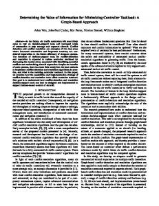
Example. To illustrate these modeling principles, a TGraph model for
state charts is presented in the following. State charts are a graphical language introduced by David Harel ([Harel 87]) for describing reactive systems. They provide a visual formalism which extends nite state descriptions by introducing hierarchy and orthogonality as additional concepts. Figure 1 shows a sample state chart. D A a/x B b
E
H
b
C
c
F
c I
a/y d
G
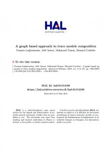
Figure 1: A Sample State Chart To model state charts inside a tool, a conceptual analysis shows, that there are four di�erent kinds of entities, namely blobs (rectangles), transitions (arcs), events, and responses (actions). Blobs may be either elementary (like B ; C ; E ; :::) or composite (like A and D ). Composite blobs may be xor-blobs (like A) containing a set of other (elementary or composite) blobs or they may be and-blobs (like D ), which contain at least two unnamed xor-blobs separated by dashed lines. Each xor-blob (as well as the state chart itself) contains exactly one so-called start blob, which is marked by a small arrow. Transitions connect blobs and are annotated by an event symbol (like a ; b ; and c ) and an optional response symbol (like x and y ), which are separated by a slash character from each other. Some blobs and all events and responses are described by strings, i.e. they a carry a string-type attribute. Following these modeling decisions every concrete state chart may be viewed as an SCGraph, i.e. as a TGraph, which re ects its abstract syntactical structure. Figure 2 shows the syntax graph corresponding to the state chart in gure 1. (For the sake of readability the edge types have only been di�erentiated coarsely in this gure.) � 5
D
elem Blob
A
and Blob B
C
E
F
G
H
I
xor Blob transition
a
b
c
d
a
event
y
response contains other relationship
x
y
Figure 2: A TGraph Representation of a State Chart
4 Schematic Description To document the class of legal models according to some modeling decisions, a suitable speci cation language for TGraph classes is needed. A graphical speci cation of the graph class for modeling state charts is shown in gure 3. The diagram captures all the informations on vertex and edge types gathered so far. It is an (extended) entity relationship(ER) description. Here a diagram is used to de ne a graph class, i.e. the class of TGraphs representing a state chart. Thus, we use ER-diagrams as a speci cation language for graph classes2. Like EBNF grammars may be used to describe and discuss string languages, ER-diagrams serve as a description of graph languages. Note, that they are not read as a generative scheme, but as a means of declarative description. 2 A complete de nition of our notation is given in [CaEbWi 94], where also a precise
graph based semantics for ER-diagrams is de ned, i.e. the class of graphs de ned by an ER-diagram is speci ed.
6
blob
source elementary blob
triggeredBy transition
sink
event
msg: string
response
action: program
reactsWith
xor blob startsWith contains and blob
name: string
Figure 3: ER-Description of SCGraphs The entity types de ned in an ER-diagram correspond to vertex types, while relationship types represent edge types. The incidence structure shown in the diagram imposes structural constraints on the class of TGraphs de ned thereby. A TGraph matches this speci cation if B the type of every vertex or edge is de ned in the ER-Diagram and B for every edge the incidence information de ned in the ER-diagram is respected.
4.1 Type Systems In the following, we will formalize the notion of a TGraph matching a speci cation given by an ER-diagram. To do this, we introduce the terms type system and incidence system, which are abstractions of what is described by an ER-diagram. Given these de nitions, the relations j=typeSystem and j=incSystem between graphs and type systems are de ned. These relations specify whether a given TGraph matches the type restrictions imposed by a type system, as well as the incidence information. 7
From a modeling point of view, objects of one type share common properties. Thus, when de ning a type t , one should also de ne the attributes that characterize the objects of t . Moreover, it is often useful to build up type hierarchies. Thus, when de ning a set of valid types, one has also to specify a subtyping relation. This is re ected by the following de nition of the schema typeSystem . domID == ID attributeSchema == attrID $ domID typeSystem typeDe nitionSet : typeID ! 7 7 attributeSchema isA : typeID $ typeID ( isA ) 2 dom typeDe nitionSet � dom typeDe nitionSet
Example. In gure 3 the entity types and the relationship types form
the domain of typeDe nitionSet . blobs have an attribute schema consisting of the attribute identi er name paired with the domain identi er string . Accordingly events and responses have non-empty attribute schemes. All other type identi ers have the empty scheme associated. The types elementaryBlob , xorBlob and andBlob are subtypes of blob , which is expressed by the inclusion of their respective rectangles. � A TGraph G matches a given type system, if the following conditions hold: B All types that are assigned to vertices or edges are de ned in the type system. B If a vertex or an edge has type t , then the value of this vertex or edge is correct with respect to the attribute schemes assigned to t and all superclasses of t in the corresponding type system. If we de ne t1 to be a subtype of t2, we express that every object of type t1 has also the properties of an object of type t2, i.e. that the objects of type t1 inherit the attributes de ned for objects of type t2. The set of all attribute de nitions which belong to a type t due to inheritance is described by the following function (here, union should be de ned appropriately as the union of sets in its argument): 8
allAttributesOfType : typeSystem ! (typeID ! attributeSchema ) allAttributesOfType = � typeSystem ; t : typeID j t 2 dom typeDe nitionSet � union (ft 0 : dom typeDe nitionSet j t isA� t 0 � typeDe nitionSet (t 0) g)
The relation j=attrSchema describes the fact, that the attribute instances of a graph element are correct with respect to an attribute schema. (Note that the de nition of j=attrSchema does not imply that there is an instance for every de nition in the given schema.) carrier : domID ! PVALUE
j=attrSchema : attributeInstanceSet $ attributeSchema 8 I : attributeInstanceSet ; S : attributeSchema � I j=attrSchema S , 8i : I � 91 d : S � rst (i ) = rst (d ) ^ second (i ) 2 carrier (second (d )) This de nition implies, that an attributeInstance may only have values for attribute identi ers, which appear only once in the attributeSchema . Thus, the following de nition solves con icts due to multiple inheritance by forbidding con icting attributes on the instance level.
j=typeSystem : TGraph $ typeSystem 8 TGraph ; typeSystem � �TGraph j=typeSystem �typeSystem , ran type � dom typeDe nitionSet 8 obj : V [ E � value (obj ) j=attrSchema
allAttributesOfType (�typeSystem )(type (obj ))
9
4.2 Incidence Systems The edges of a TGraph speci ed by an ER-diagram may be incident only with vertices, whose types t to the description. The schema incidenceSystem speci es restrictions on the incidence structure of a TGraph. Given an edge type t , incidences (t ) determines the types of the start and goal vertices. incidenceSystem typeSystem incidences : typeID !7 (typeID � typeID ) dom incidences � dom typeDe nitionSet ran incidences � dom typeDe nitionSet � dom typeDe nitionSet The relation j=incSystem de nes whether a given TGraph G satis es an incidence system. This is the case, if for every edge e of G the typing conditions for its start and its goal vertex are respected. (Here, inheritance has to be taken into account, too.) j=incSystem : TGraph $ incidenceSystem 8 TGraph ; incidenceSystem � �TGraph j=incSystem �incidenceSystem , 8 e : E ; t : typeID j type (e ) = t � type (�(e )) 2 f t 0 : typeID j t 0 isA� rst (incidences (t )) g ^ type (!(e )) 2 f t 0 : typeID j t 0 isA� second (incidences (t )) g
Example. From Figure 3 on may derive that incidences (source ) = (transi ?
tion ; blob ) holds, which e.g. implies, that the types of a goal vertex v of a source -edge e may only be blob , elementaryBlob , xorBlob , or andBlob . �
4.3 ERSpeci cations The speci cation given by an ER-diagram consists of a type system and a corresponding incidence system. A TGraph matches a speci cation if it matches the type and incidence claims speci ed therein. 10
ERSpeci cation typeSystem incidenceSystem
j=ERSpeci cation : TGraph $ ERSpeci cation 8 TGraph ; ERSpeci cation � �TGraph j=ERSpeci cation �ERSpeci cation , �TGraph j=typeSystem �typeSystem ^ �TGraph j=incSystem �IncidenceSystem Thus, the class of TGraphs given by an ERSpeci cation Spec is the set of those TGraphs G with G j=ERSpeci cation Spec .
5 Additional Constraints So far, it has been discussed how to de ne classes of TGraphs by specifying vertex and edge types and restrictions on possible incidences in an ERdiagram, as well as how to de ne appropriate attribute schemes for objects and relations. Often, this information alone does not su�ce to describe an application domain in a satisfying manner. Hence, the diagram still has to be extended by additional predicates which speci y additional constraints to complete the speci cation language. Some of these predicates, like e.g. degree restrictions might also be expressed graphically in the diagram, but more elaborate (especially global) constraints must be stated explicitly.
Example. In state charts, for instance, the set of contains -arcs de nes a
tree-like hierarchy on blobs. This is not expressed in the diagram. In this sense, the speci cation of the class of TGraphs modeling state charts is still incomplete. In graph theoretical terms, the described constraint is given by the following predicate: isTree(eGraph(edges(contains )) 11
Here, edges(contains ) is the set of all edges e with type (e ) = contains . eGraph returns the graph induced by a set of edges, and isTree is a predicate on graphs. Further conditions on state charts are: a blob is either elementary, or an xor-blob, or an and-blob, elementary blobs are not re ned, xor-blobs contain exactly one start blob, and and-blobs consist of xor-blobs, only: 8 q : nodes(blob ) � type (q ) 2 felementaryBlob ; xorBlob ; andBlob g ^ if type (q ) = elementaryBlob then outdegree(q ; contains ) = 0 ^ if type (q ) = xorBlob then outdegree(q ; startsWith ) = 1 ^ if type (q ) = andBlob then (q !contains) � nodes(xorBlob ) �
To describe additional constraints on graph classes the constraint language GRAL ([EbeFra 92]) has been developed. GRAL is a Z -like notation to describe structural properties of TGraphs, which can be translated into e�cient algorithms that test the property described ([CapFra 91]). A GRAL predicate is a rst order predicate logic term containing only elements, which can be tested by polynomial algorithms. Basic elements of GRAL are B a set of predicates to describe basic properties of graph elements (like isIsolated; isSink ), or graphs (like isTree; isConnected; isBipartite ) B a set of functions to compute sets of vertices (like nodes) and sets of edges (like edges) of a given type, or induced subgraphs (like eGraph). B predicates and functions on sets and numbers, B logical operators (like ^; _) and quanti ers (like 8), which are allowed to range over nite sets, and B (regular) path expressions. A path expression describes a path in a graph in an abstract manner. A simple path expression consists of a single edge ( ; !; �). Each edge symbol may be annotated with restrictions on its type and attributes (e.g. !contains). Analogously, restrictions on nodes reached by following an edge can be expressed (e.g. !contains�elem). Simple path expressions may be combined to form more complex ones. Here, only regular structures (sequence, alternative, iteration) are allowed. Path expressions may be applied in post12
x notation to vertices, thus delivering the set vertices which are reachable via a path matching the description, or they may denote predicates, if they are applied to two vertices in in x notation. Sets de ned by path expressions may be computed by appropriate search algorithms in O(#E � s ) time, if s is the number of symbols in the path expression ([CapFra 91]).
Example. To describe the set of all transitions in a state chart that
are enabled through a given event e by a blob q , the following expression su�ces: f t : nodes(transition ) j q �contains source t !triggeredBy e g �
Since GRAL - as a constraint description language - allows also to de ne the type system and the incidence structure of graph classes. It depends on the user, where he puts the borderline between the ER-like description and the GRAL-part. We recommend to use the diagrammatic description as far as possible and to use GRAL only for the addition of further constraints, which are not expressible graphically by the ER-dialect chosen.
6 Programming With Graph Based Models Up to now, we described the class of graphs used for modeling and gave a an approach to de ne subclasses as model classes for practical applications which consists of a combination of a graphical and a textual description. In this section we sketch how graph based models speci ed in this way may be implemented. TGraphs may be handled e�ciently by graph algorithms written in a pseudocode according to the algorithmic interface described in gure 4. Using an implementation technique like the one described in [Ebert 87] a direct implementation of pseudocode algorithms is possible, without any intermediate transformation. If the traversal operations are implemented in optimal time, complexity analysis of algorithms also carries through to the nal implementation. 13
procedure init () for all v in V do ... end for all e in E do ... end for all e in �(v) do ... end for all e in �+ (v) do ... end for all e in �?(v) do ... end procedure vertexCount(): nat0 procedure edgeCount(): nat0 procedure isEdge (v, w: vertex): edge procedure areNeighbours (v, w: vertex): procedure alpha (e: edge): vertex procedure omega (e: edge): vertex procedure this (e: edge): vertex procedure
that (e: edge): vertex
initializes the graph as empty processes all vertices v processes all edges e processes all edges e incident with vertex v processes all edges e going out of vertex v processes all edges e going into vertex v returns the number of vertices returns the number of edges returns an edge from v to w edge returns an edge between v and w returns the start vertex of edge e returns the end vertex of edge e returns the vertex from whose �-sequence e was taken returns the other vertex of e with respect to this (e)
Figure 4: Algorithmic Interface for TGraphs The algorithmic interface has been realised by C++-software package ([DaEbLi 94]), which may be used for programming with TGraphs. This package works on the edge-oriented basis described in this paper, where the data type edge includes the edge object plus its direction. This allows to view a graph as being undirected or directed without any change of its representation. The view on the graph is only determined by the interface operations that are used. Internally graphs are represented by symmetrically stored forward and backward adjacency lists ([Ebert 87]). The sets of attribute instances belonging to vertices and types are implemented by application dependent C++-objects, thus using the multiple inheritance concept of the language to implement the analogous concept in TGraphs. Since according to the modeling approach given above ER-diagrams themselves may easily be modeled as ERGraphs (according to the (meta)-ERschema in gure 5), the graph interface can be realised in such a way that creation and deletion of edges are controled by a constraint checker, which consults the ERGraph of the graph class with every updating operation. If G is an ERGraph, which describes a graph class, its entity vertices correspond to vertex types and its relationship , role , and grouping vertices 14
ERItem
genkind: {gen,tot}
name: string
entityOrRelationship kind: {norm, inj} limits: IP ( IP IN )
entity general
hasAsComponent
aggregate
aggregatesTo
role
groupsTo
generalizesTo group
hasAsComponent
comes from
kind: {norm, inj} limits: IP ( IP IN )
goes to
limits: IP ( IP IN )
grouping
limits: IP ( IP IN ) value: string
relationship
hasAttribute
attribute
hasDomain
expression
Figure 5: Schema for ERGraphs correspond to edge types. The generalizesTo edges give the isA-relation. Furthermore, the hasAsComponent , aggregatesTo , groupsTo , comesFrom , and goesTo edges contain the incidence information, and the subgraphs induced by the sets of entityOrRelationship , attribute , and expression vertices describe the attribute schemes3. In addition to the checking via the ER-diagram, the checkings procedure derived from the GRAL predicates may be activated every time, a modi cation of the graph is performed. Thus, the declarative description of TGraph classes is directly usable in consistency assurance. 3 [CaEbWi 94] contains a formal description of the type system and the incidence system
de ned by an ER-diagram via its ERGraph.
15
7 Conclusion and Related Work In this paper we gave an overview on our approach of using graph theory and graph algorithms in a consistent software technological manner in practical applications. A formal de nition of the class of TGraphs was given together with a declarative approach of specifying subclasses for modeling purposes by giving their type and incidence structure graphically and by supplying a constraint speci cation language, which is translatable into e�cient test procedures. Since this language includes regular path expressions, it already leads quite far. All aspects are implementable accordingly without any gap. Thus TGraphs build a framework which uniformly supports the aspects of expressiveness, formality, and e�ciency. In the KOGGE project ([Ebert 94]) software requirement and design documents are modeled inside a Meta-CASE-tool by TGraphs. Here, graphs are used as internal data structures exactly in the way described above. The modelling classes are speci ed using ER-diagrams and GRAL, and the repository component of the system assures that all speci ed integrity constraints are automatically kept by the system. Since the class of TGraphs is de ned in terms of objects, relations, attributes, etc. it ts very well into today's object-oriented way of thinking. Thus, TGraphs models are object-oriented structural models. Their de nition shows also a way to formalizing structural aspects of object-oriented description. The approach of characterizing graph classes by ER-diagrams, which have a widespread use in information modeling in database systems, may as well be read as a de nition of a graph based data model for databases, including a powerful speci cation language for consistency conditions, namely GRAL. Comparable work has been done by e.g. Paredaens and others ([GyPaGu 90]) and Consens and Mendelzon ([ConMen 90]), where the emphasis lies on the de nition of suitable query languages while we concentrate on the modeling process. Foundations of declarative speci cation for graph languages have been explored by Courcelle ([Courcelle 90]). He showed that graph properties describable in monadic second order logic (MSOL) are e�ciently testable for large graph classes. The speci cation language proposed in this paper is 16
less powerful then MSOL (by o�ering su�cient expressive power for practical applications). We can guarantee that our declarative speci cation lead to e�cient implementations, which is also shown by our translator in a constructive manner. The concept of declarative graph class speci cation contrasts with graph grammar approaches, which assure constraints on graphs by specifying the operations, which build or update the graph. The graph grammar based approach has been used in the IPSEN project by Nagl and others ([EnLeNa 92] where graph grammar based speci cations are used in the development of software engineering environments. In this context, the operational speci cation language PROGRESS ([Schuerr 91]) has been de ned that allows users to specify even complex graph transactions. Furthermore, implementation is supported by a powerful graph database system. In the graph grammar based approach to graph class speci cation it is quite easy to implement tools that control the construction of graphs matching the speci cation (e.g. syntax directed editors). On the other hand, given a more declarative speci cation it is easier to test whether a given graph is correct with respect to the speci cation. Test procedures for speci ed graph properties may be embedded in a module managing the graph structure and thus be separated from application programs. Any test may be invoked at any point in time, on system or user demand. Thus, exible strategies for consistency control might be implemented. It is depends on the goals of graph based modeling in an application context which kind of speci cation should be used. From a modeling point of view, the declarative approach seems to be more intuitive or natural since the user is able to describe the class of graphs he thinks of without having to think of operations.
References [CaEbWi 94] [CapFra 91]
Martin Carstensen, Jurgen Ebert, Andreas Winter. Entity{Relationship{Diagramme und Graphenklassen. to appear as: Fachbericht Informatik 1994. Universitat Koblenz 1994. Carla Capellmann, Angelika Franzke. GRAL: Eine Sprache fur die graphbasierte Modellierung. Universitat Ko17
[ConMen 90] [Courcelle 90] [DaEbLi 94] [Diller 90] [EbeFra 92] [Ebert 87] [Ebert 93] [Ebert 94] [EnLeNa 92]
[GyPaGu 90]
blenz, Diplomarbeit, 1991. Mariano P. Consens, Alberto O. Mendelzon. GraphLog: a Visual Formalism for Real Life Recursion. In: Proc. 9th Symposium on Principles of Database Systems. New York: ACM Press, 1990, pp. 417-424. Bruno Courcelle. Graph rewriting: An algebraic and logic approach. In: Jan van Leeuwen (ed.): Handbook of Theoretical Computer Science, Vol. B. Amsterdam: Elsevier 1990. pp. 193 - 242. Peter Dahm, Jurgen Ebert, Christoph Litauer. Das EMS-Graphenlabor. in preparation. Anthony Diller. Z : An Introduction to Formal Methods. Wiley 1990. Jurgen Ebert, Angelika Franzke. Speci cation of a Graph Based Data Model for a CASE Tool. Universitat Koblenz, Fachbericht Informatik 5/92 Jurgen Ebert. A Versatile Data Structure For EdgeOriented Graph Algorithms. Communications ACM 30 (1987,6), 513-519. Jurgen Ebert. E�cient Interpretation of State Charts. in: Zolt�an E� sik (Ed.). Fundamentals of Computation Theory (FCT '93), Szeged, Hungary. Berlin: Springer, LNCS 910, 1993, pp. 212-221. Jurgen Ebert. KOGGE: A Generator for Graphical Design Environments. in preparation. Gregor Engels, Claus Lewerentz, Manfred Nagl, Wilhelm Schafer, Andreas Schurr. Building Integrated Software Development Environments. Part I: Tool Speci cation. ACM Transactions on Software Engineering and Methodology 1 (1992, 2), 135 - 167. M. Gyssens, J. Paredaens, D. van Gucht. A graphoriented object database model. In: Proc. 9th Symposium on Principles of Database Systems. New York: ACM Press, 1990, pp. 417-424. 18
[Harel 87] [Schuerr 91] [Spivey 92]
David Harel. Statecharts: a Visual Formalism for Complex Systems. Science of Computer Programming 8 (1987,3), 231-274 Andreas Schurr. Operationales Spezi zieren mit programmierten Graphersetzungssystemen. Wiesbaden: Deutscher Universitatsverlag, 1991. J.M. Spivey. The Z Notation - A Reference Manual. New York: Prentice Hall, 1992.
19