SSC02-IV-6 A Distributed Computing Architecture for Small Satellite and Multi-Spacecraft Missions Bryan Palmintier∗, Christopher Kitts∗, Pascal Stang∗ and Michael Swartwout∗∗ ∗
Robotic Systems Laboratory, Santa Clara University, Santa Clara CA 95053 (408) 554-4382,
[email protected],
[email protected],
[email protected] ∗∗
Department of Mechanical Engineering, Washington University in St. Louis, St. Louis MO 63130 (314) 935-6077,
[email protected]
Abstract. Distributed computing architectures offer numerous advantages in the development of complex devices and systems. This paper describes the design, implementation and testing of a distributed computing architecture for low-cost small satellite and multi-spacecraft missions. This system is composed of a network of PICmicro® microcontrollers linked together by an I2C serial data communication bus. The system also supports sensor and component integration via Dallas 1-wire and RS232 standards. A configuration control processor serves as the external gateway for communication to the ground and other satellites in the network; this processor runs a multitasking real-time operating system and an advanced production rule system for on-board autonomy. The data handling system allows for direct command and data routing between distinct hardware components and software tasks. This capability naturally extends to distributed control between spacecraft subsystems, between constellation satellites, and between the space and ground segments. This paper describes the technical design of the aforementioned features. It also reviews the use of this system as part of the two-satellite Emerald and QUEST university small satellite missions. have an architecture that enables collaborative processing focused on a specific task (e.g. parallel computation), and/or each may be optimized to efficiently execute particular tasks or control specific subsystems (e.g. smart peripherals).
Table of Contents 1. 2. 3. 4. 5. 6. 7. 8.
Introduction Advantages of a Linear Bus Architecture System Design Application to Small Satellite Missions The Architecture as an Experiment Future Work Conclusions Acknowledgements
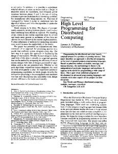
The architecture of a computing system (whether centralized or distributed) refers to the physical and logical framework used to interconnect components. It determines the pathways for inter-subsystem data transfer and may have a large bearing on both wiring harness size and modularity. As depicted in Figure 1, typical architecture definitions include the following (in some cases, they are not mutually exclusive): • A star (centralized or distributed) architecture consists of a central processing unit that is directly connected via dedicated links to every other computational unit; this approach often leads to large wiring harnesses and a dependency of the central computer’s hardware/software on the design of the peripheral units. From a computational point of view, a star configuration is the prototypical example of a centralized architecture when the connected components don’t have processors. A star configuration, however, can be used in a distributed framework if these components have processors. • In a ring (distributed) computing architecture, processors are linked in a closed chain with
1. Introduction Distributed computing architectures offer numerous advantages in the development of complex devices and systems. These advantages include well-defined interfaces, flexible composition, streamlined integration, straightforward function-structure mappings, standardized components, incremental testing, and other benefits. In the context of this paper, distributed computing refers to computational decentralization across a number of processors which may be physically located in different components, subsystems, systems, or facilities. These processors may be general-purpose computers with data/application sharing capabilities (e.g. a typical personal computing network), they may Palmintier
1
16th Annual AIAA/USU Conference on Small Satellites
•
•
•
communication protocols for arbitration, error handling and other functions is a straightforward strategy. Ultimately, even the command and data handling interface can be standardized. For the current development effort, the ultimate goal of this standardization was to achieve component-level modularity such that components could be easily connected, disconnected, replaced, swapped and/or upgraded in a rapid and transparent manner.
communication typically facilitated by a “token” which is passed from one processor to another; rings typically lead to small wiring harnesses, cause minor design dependencies among subsystem implementations, and may suffer from interrupted communication if/when subsystems are disconnected or fail. Linear bus distributed computing architectures typically consist of a standardized, shared, linear data bus to which all subsystems are connected; while this often leads to small wiring harnesses and non-problematic (dis)connections to/from the bus, it requires a well-designed communication protocol governing when processors can transmit data over the bus. Hybrid architectures occur when one or more instances of the aforementioned architectures are used to link different processors within a single system. This is often done given that different inter-processor communication requirements often are best addressed by different architectures. Layered architectures arise when more than one of the aforementioned architectures is used to link to the same processors within a single system. For example, the same processor may have a low data rate bus architecture for command and control information but a direct, dedicated, high data rate connection for science data. This is often done given that different processor functions often are best addressed by different architectures.
While distributed computing systems and their advantages are common in modern personal computer, consumer product, industrial automation, automotive, and other industries, they have been slowly adopted in the satellite industry. Recent initiatives such as the NASA/JPL X2000 development program have recognized the advantages of distributed computing strategies and are beginning to develop such systems for space flight. The authors (all of whom have served as systems engineers and/or managers of one or more university small satellite projects with centralized computing architectures) are pursuing the development and use of a linear bus command and data handling architecture for use in small and multi-spacecraft systems. The adoption of this strategy is in and of itself an experiment that explores the true benefits and costs of such an approach. The team currently believes that the following benefits will be realized:1 • In the design stage, the distributed system will simplify the command and data flow within the satellite by clarifying which specific component is responsible for each task and what information exchange is required to initiate the task; ideally, each functional block in the system’s signal flow diagram will map directly to a physical box on the satellite. Furthermore, this characteristic will allow easy hierarchical scaling of the functional and data flow designs for multi-satellite missions and comprehensive space/ground segment systems.
2. Advantages of a Linear Bus Architecture The use of a linear bus distributed computing architecture leads to a simple and relatively small data bus that promotes standardized methodologies for interfacing at a range of levels. At the signal level, standardization of physical interconnections is a natural objective. At higher levels, standardization of data
CPU
Power
Telem.
Science
Comm
Data Bus (a) Centralized Architecture. (b) Ring Architecture
(c) Linear Bus Architecture.
Figure 1 – Comparison of Typical Computing Architectures.
Palmintier
2
16th Annual AIAA/USU Conference on Small Satellites
•
•
•
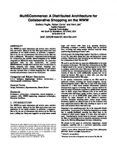
subsystem development and to leverage economies of scale, a standard subsystem motherboard based around the PIC16F877 microcontroller was developed. This standard motherboard, shown in Figure 2, includes power/data connectors, power control circuitry, latchup protection, and full access to the PIC’s ports.
During development and integration, the distributed architecture will promote the rigorous and independent test/verification and the controlled, incrementally integration of each subsystem/component. Such an achievement will assist in de-coupling the reliance of one subsystem’s development on the operation of another (e.g. such as the central processing unit in most centralized architectures). Furthermore, with network bus “gateways”, components can be easily integrated remotely using TCP/IP or other protocols to bridge and test subsystems being developed at different locations. On-orbit, the distributed architecture will simplify resource sharing (e.g. computational power, memory, etc.) among components, subsystems, and even satellites. It also promotes fault tolerance since computational functions can be supplied by other units (possibly even located in other spacecraft or on the ground) in the event of component outages. When exploited in a multi-satellite mission, the distributed architecture will allow components deployed across multiple satellites to interact in much the same manner as those within a single satellite. This has significant implications in the simplification of collaborative processing schemes both at the conceptual and implementation levels.
PIC16F877 Micro Controller The PIC16F877 is a single chip computer, requiring only an external clock source. It resides in a 40-pin package with 8 kwords of ROM and 384 bytes of RAM. This particular PICmicro® has many built-in peripherals, including I2C capabilities and an 8 channel A/D converter. Another attractive feature is its low power consumption: less than 100 mW at max speed (20Mz) and less than100µW in its low-power sleep mode. The PICmicro® also has a simple “RISC” instruction set, which allows fast and efficient execution. One of the major shortcomings of the PICmicro® is its lack of support for external memory. The development team has worked around this deficiency by interfacing a simple custom SRAM capable of storing up to 2.5Mbytes of data for subsystems that require additional storage. Less memory intensive subsystems will store data in an external serial EEPROM. Software
3. System Design
The current design consists of a network of PICmicro® PIC-based processors linked by a hybrid bus consisting of a high-bandwidth Phillips I2C (Inter-Integrated Circuit) data bus and a low-bandwidth Dallas Semiconductor “1-wire” microLAN for standard vehicle telemetry.
A common library of low-level hardware routines, as well as standardized I2C bus interfacing has been developed to simplify subsystem programming. The library includes support for: • I2C, including high level protocol • RS232, for debugging • A/D conversion at up to 18kHz • Timer control to synchronizing fast events • Real Time clock base for slower events, timestamping, and scheduling. • External memory support (1.5 MB SRAM or 64KB EEPROM) • Simplified interface for translating I2C commands into subsystem function calls • Standardized, run-time configurable “super-loop” structure with flags to allow simple multi-tasking.
Subsystem Motherboard2
Configuration Control Computer
For the distributed architecture to work effectively, it is not necessary for all subsystems to use the same processor. As long as the standard bus interface is observed, processor differences are transparent to all other subsystems on the bus. But to simplify baseline
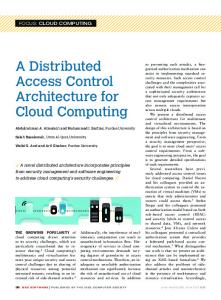
A separate Configuration Control Computer uses a 16MHz PIC17C56 (16Kx16bit ROM, 904Byte RAM, with built-in I2C and 2 asynchronous serial ports) running the Pumpkin Salvo Real Time Operating System (RTOS).
Given the aforementioned advantages of a distributed computing approach, the research team is focusing its efforts on the development of a robust and widely applicable linear bus design. Given this approach, the team sought to develop a system with a balance of simplicity and cost while also a) providing performance capable of supporting research-quality microsatellite instrumentation, and b) being feasible for use by student design teams.
Palmintier
3
16th Annual AIAA/USU Conference on Small Satellites
(a) Standard PIC16F877-based Subsystem Board.
(b) PIC17C56-based Configuration Control Board.
Figure 2 – Functional Motherboard Prototypes: reduced wiring, and speed. Additionally, protocol support for multiple nodes sharing control of the bus (multi-master) was desired, though not strictly required, for some experiments. Given these parameters, detailed consideration was given to three simple protocols commonly used in embedded systems: • Controller Area Network (CAN): CAN is used extensively in automotive and industrial control applications. However, CAN is most suited to industrial-scale users, and is therefore overly complex for the current effort. The increasing commercial availability of stand-alone CAN chips and microcontrollers with integrated CAN support may make CAN more attractive in the future. • Serial Peripheral Interface (SPI): SPI is simple and widely used, but the interface doesn’t scale well to arbitrarily sized networks since it requires additional wires for address lines. In addition, multi-master support requires extending the baseline specification. • Inter-Integrated Circuit (I2C): I2C is used in audio/visual equipment, on PC motherboards, and in “smart” batteries. This protocol easily scales to networks of arbitrary size and includes built-in support for multiple masters. However, it doesn’t provide existing, suitable high-level communication protocols.
Originally envisioned to simply characterize data bus performance and to provide a redundant path between the communication system and the I2C bus, the scope of this subsystem has grown due to difficulties with the originally selected commercial processor, the ability to leverage the capabilities of the Salvo RTOS, and the advantages of reusing software developed for the subsystem motherboards. A 17-series PIC was chosen as the heart of this system due to its expanded memory resources and RTOS compatibility. On top of the RTOS, several software tasks execute in order to process I2C and Dallas data packets, to service communication subsystem data flow, to efficiently enable software uploads, and to interface expert system execution with satellite commands and telemetry. Data Bus The data bus specification required careful consideration since it forms the data backbone of the entire satellite. There are numerous existing standards that span the high and low level aspects of distributed computing systems, especially in distributed industrial control applications.3,4,5 However, these standards typically assume computational and power resources not available in small satellites. Therefore, the team researched simpler communication protocols, those typically used at the chip and board scale (instead of the room or facility scale). This allowed a design that met power, voltage, and computational constraints but required the custom development of the high level protocols.
Given these options, the development team chose to use the I2C bus. Conveniently, there are many simple, off the shelf devices available for I2C, (digital I/O, A/D converters, EEPROM, microprocessors, etc.) Low level I2C
Protocol Selection2
I2C is a synchronous serial protocol that uses only 2 wires, one for data (SDA) and one for clock (SCL). It also requires a common ground. It operates at 100 kbps
The team decided to only consider synchronous serial protocols given the desired balance of simplicity, Palmintier
4
16th Annual AIAA/USU Conference on Small Satellites
in standard mode. Faster modes (400kbps and 3.4 Mbps) are also specified, but fewer devices support these modes. The protocol is specified to a fairly high level from reading and writing to multi-master support and arbitration.
because it allows subsystems to change and expand their functionality without requiring extensive system knowledge by operations personnel. Due to time limitations, these standard commands will only be incorporated into some of the nodes on the system.
Both lines are connected wired-AND, which allows for arbitrary numbers† of devices and which facilitates “hot swap” addition and removel of devices without interrupting the bus.
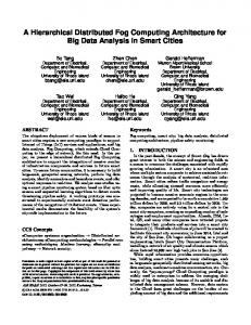
Packet Definition Command Packet
From Command (5 bytes) Check
Data Packet
Communication is always initiated by a master, which also drives the clock. Each I2C message consists of an arbitrary number of 9 bit “words.” These words are 8 bits of information (supplied by the current “transmitter”) plus an acknowledge (from the “receiver). The first word of the message sets the address (7bits) and the communication direction (Read or Write). In read mode, after the first acknowledge, the slave begins transmitting and the master becomes the “receiver.”6,7
Size
Data (>20
20
-
31
Coupling
Direct / Open Collector
Open Collector
Direct
Drct./Induct./Fbr.
Inductive
Redundancy
None
-
Varies
Varies
varies
Max Msg. Length
5/127 Bytes
-
2Bytes/34KB
-
64 Bytes
Data Integrity
8bit checksum
None
Voltage
0/5V
0/5V
-10/0/+10V
-10/0/+10V
Fault Tolerance
BM/D1W Pwr. Cntrl
-
Varies
Varies
BM/redundancy
Power Consumption
3.5mW