A Fault-Tolerance Protocol for Parallel Applications with Communication Imbalance Esteban Meneses School of Computing Costa Rica Institute of Technology Cartago, Costa Rica
[email protected]
Abstract—The predicted failure rates of future supercomputers loom the groundbreaking research large machines are expected to foster. Therefore, resilient extreme-scale applications are an absolute necessity to effectively use the new generation of supercomputers. Rollback-recovery techniques have been traditionally used in HPC to provide resilience. Among those techniques, message logging provides the appealing features of saving energy, accelerating recovery, and having low performance penalty. Its increased memory consumption is, however, an important downside. This paper introduces memory-constrained message logging (M CML), a general framework for decreasing the memory footprint of message-logging protocols. In particular, we demonstrate the effectiveness of M CML in maintaining message logging feasible for applications with substantial communication imbalance. This type of applications appear in many scientific fields. We present experimental results with several parallel codes running on up to 4,096 cores. Using those results and an analytical model, we predict M CML can reduce execution time up to 25% and energy consumption up to 15%, at extreme scale. Keywords-fault tolerance; message logging; communication imbalance
I. I NTRODUCTION Many scientific fields are addressing challenging problems thanks to the wide availability of supercomputing power. Machines with a vast number of processors enable the exploration of scenarios that would have been considered too complex a decade ago. As supercomputers evolve, they incorporate more components to satisfy the computational needs of scientists and engineers. However, this relentless growth in the size of the machines brings an undesirable consequence: lower reliability. The high failure rate of future supercomputers has been recognized as one of the major roadblocks to achieve exascale [1], [2], [3]. It is imperative to provide extreme scale systems with some form of fault tolerance mechanism. Otherwise, the menacing threat of frequent failures will render future systems unusable [4]. Rollback-recovery techniques have long been the preferred fault tolerance method in high performance computing (HPC) [1], [3], [5]. The general idea behind rollback-recovery is simple: save the state of the system at checkpoints, rollback to the latest checkpoint in case of a failure, and resume execution. The checkpoint/restart scheme has adopted several variants [5], [6], [7]. A promising variant is called message logging, which logs application messages as the program
Laxmikant V. Kal´e Department of Computer Science University of Illinois at Urbana-Champaign Urbana, Illinois, USA
[email protected]
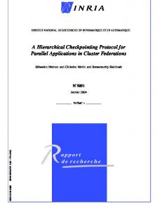
executes. A failure in the system will only roll back the failed nodes, and have the rest of the system replay the stored messages to recover the restarted nodes. Message logging has been demonstrated to save energy [8], [9], reduce recovery time [10], and have a small overhead [11], [12]. The main drawback of message logging is its potentially large memory footprint due to the message log. This paper presents a new framework to reason and design new message-logging protocols that trade off a reduction of the memory pressure for an increase in the recovery effort. Figure 1 presents a general view of the different alternatives to store communication in a message-logging infrastructure. The process-based approach has dominated the literature on the topic. In that view, a process is output-logging or inputlogging, depending whether it stores the outgoing or the incoming communication, respectively. Or, it does not store communication and it becomes non-logging. Most messagelogging protocols use output-logging processes [5], [11], [13]. However, some scenarios may call for new protocols where a combination of the above types of processes provides a more efficient solution. Another approach for message-logging protocols is the channel-based, in which each channel either logs outgoing, incoming, or no communication. This perspective provides a more general framework for developing new message-logging strategies that radically decrease the memory footprint and minimally impact the recovery effort. This paper describes a channel-based protocol that targets applications with communication imbalance. This paper makes the following contributions: • •
•
•
Section III offers a characterization of communication imbalance in parallel applications. Section IV provides the design of memory-constrained message logging (M CML), a general framework for developing protocols aimed at reducing the memory footprint of message logging. Section V presents experimental results showing the reduction in memory overhead of M CML with a collection of representative applications. Section VI extends an analytical model to provide performance projections of M CML at extreme scale.
Process-based
output-logging Communication logged
Channel-based
input-logging
non-logging
Communication not logged
Fig. 1: Communication-Logging Alternatives. II. BACKGROUND A. System Model We conceive a parallel application as a set P of processes. Each process holds a portion of the application’s data in its own private memory. The only mechanism to share information is through message passing. The state of an application at any point in time is the collection of the state of the individual processes plus the set of in-flight messages. The state of the application can be determined using a distributed systems algorithm for global snapshots [14]. This description captures popular parallel programming paradigms, in particular the Message Passing Interface (MPI). An application runs on a system that comprises a set of nodes. The nodes are connected through an interconnect with channels that respect first-infirst-out (FIFO) ordering. Therefore, two messages from same source and same destination can not be reordered. The nodes of the system may fail according to the fail-stop model [5]. That means, a failed node becomes immediately unresponsive and has to be replaced. We assume the system has enough spare nodes to replace all failed nodes. Alternatively, the average repair time of nodes is smaller than the mean-timebetween-failures (MTBF) of the system. B. Checkpoint/Restart Traditionally, fault-tolerance approaches in HPC belong to the rollback-recovery family [5]. More specifically, checkpoint/restart is the de facto standard implementation of reliable supercomputing applications. Checkpoint/restart is based on the principle that an application will periodically save its state to stable storage and it will restart from the previous checkpoint if there is a failure in the system. There are many variants of checkpoint/restart, but all follow the same general guideline. Normally, the checkpoints are stored in the network file system. That approach does not scale well as it may cause congestion during checkpoint time [3]. A variant to that approach is called double-local checkpoint [6]. In that case, every node stores two copies of its checkpoint: one in its own local storage (memory, SSD, local disk) and one in the local storage of its checkpoint buddy. Should a node fail, all nodes will rollback using its locally stored checkpoint. The checkpoint buddy of the failed node will provide a checkpoint to the replacement node. This approach has been shown to
be scalable and it can recover from most failures in real HPC systems [10]. Other variants of checkpoint/restart create a multilevel framework where checkpoints can go to local or shared storage [7]. These frameworks usually provide a model to determine the best combination of the different types of checkpoints. Checkpointing can also be synchronized, i.e., use global synchronization points to checkpoint the application. Synchronized checkpoint/restart does not require to store the state of the channels as part of the checkpoints, because it is guaranteed that at checkpoint time there are no inflight messages. It has general applicability as most HPC applications feature global synchronization phases. Also, the size of synchronized checkpoints may be drastically reduced if the programmer writes checkpoint methods that only save the necessary data (also called application-level checkpoint). C. Message Logging The major downside of checkpoint/restart is that it requires a global rollback: all processes are forced to resume execution from the latest checkpoint. That leads to a huge waste of time and energy [8], [9]. An enhancement to checkpoint/restart is message logging [15], a technique that stores checkpoints and, in principle, stores all the messages in an execution. There are multiple implementations of message logging for HPC systems [10], [16], [17]. The benefit of storing communication is that a failure only requires the failed node to rollback, hence only local rollback is needed. To achieve a correct recovery, message-logging protocols usually rely on the piece-wise deterministic (PWD) assumption, which states that storing all non-deterministic decisions in a program is sufficient to obtain a consistent recovery. Message logging uses a mechanism called determinants to store non-deterministic decisions. For example, message reception order is, in general, non-deterministic. A determinant d generated after the reception of message m is a tuple with four components: d = #m = hsender, receiver, ssn, rsni. Every time a message from sender with a sender-sequence-number (ssn) is received at receiver, it gets a unique receiver-sequencenumber (rsn). Determinant d uniquely represents the reception of a message and if provided to a recovering process, it will ensure the recovery exactly replicates the events that happened before the crash. We will assume message reception is the only source of non-determinism for the rest of the paper. There are many flavors of message logging, but a promising alternative is called simple-causal message logging [11] (S CML), a particular case of family-based message logging [15]. This algorithm has shown low overhead and high scalability for a representative group of HPC applications. Figure 2 presents an execution using S CML. Messages are stored at the sender. After a message is received, a determinant is generated. For instance, message m1 from A to C is associated with determinant d1 . That determinant must be piggybacked on all outgoing messages, until an acknowledgment (a1 ) has been received. After a process fails, the processes storing determinants of the failed process provide those determinants to ensure a consistent recovery.
Time
m2⊕d1
a1
a2 m4
•
Fig. 2: Simple Causal Message Logging (S CML). D. Related Work
III. A PPLICATIONS WITH C OMMUNICATION I MBALANCE Although team-based message logging demonstrated to be an effective mechanism in reducing memory overhead of message-logging protocols, its fundamental premise is that an application features a well-structured, balanced communication pattern. That is true for most scientific computing applications, but there is an emerging type of parallel programs that exhibit a non-uniform, communication-imbalanced profile. In this class of applications, there is usually a skewed distribution of the communication load, with few processes transmitting significantly more bytes than the rest of processes in the system. In addition, sometimes the communication graph is unstructured, resulting in the team-based approach being ineffective. There are various reasons for the emergence of communication imbalance patterns in parallel applications: • Dynamic load imbalance: as the program executes, some processes may accumulate more data, potentially performing more computations and effectively communicating more bytes to other processes. For instance, in particle-interaction programs, hot-spots agglomerating many particles can form on few processes [22]. • Adaptive communication algorithms: where the exact target of a message cannot be statically determined, but
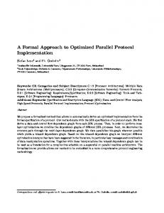
A. Communication Profile Understanding the communication characteristics of applications with communication imbalance is fundamental to develop effective message-logging approaches. We introduce the communication analysis of applications by showing the exchange matrix of two benchmarks in Figure 3. The figure displays a heatmap of the point-to-point communication volume between every pair of sender and receiver MPI ranks. Collective communication operations, in the applications studied, carry a small portion of the data, and will be ignored in the rest of the paper. We contrast a program with balanced communication (NPB-CG, a conjugate gradient computation) in Figure 3a versus a program with communication imbalance (MiniAMR, an adaptive mesh refinement algorithm) in Figure 3b. Figure 3a presents a well-structured exchange pattern, with every active channel (pair of sender-receiver) sending exactly the same amount of bytes. In contrast, Figure 3b displays a very nonuniform distribution of the communication between pairs. Besides, there is no constant pattern repeated across the main diagonal. The communication matrix is, however, symmetric. 60 50 Receiver Rank
An important drawback of message logging is the increase in memory pressure due to the message log. Message logging may not be practical for an application sending large messages with high frequency, since the total physical memory can be quickly exhausted. Recently, hierarchical protocols have been explored [18], [19], [12]. In these protocols, processes are grouped into teams. Messages crossing team boundaries are logged, but messages within teams are not logged. Therefore, if teams manage to capture a high volume of the communication in the application, the size of the message log reduces dramatically. Teams act as recovery units: if one member fails, the whole team rolls back. Therefore, team-based message logging trades off a reduction of memory pressure for an increase in the recovery effort. Fortunately, several applications in HPC have a structured communication pattern with clusters of processes enclosing a high portion of the communication volume [20]. These communication patterns often result from traditional parallel programming patterns and can be found in multiple programs. The team-based approach was also extended to work in conjunction with parallel computing platforms that allow load balancing [21]. Therefore, teams can be dynamic and adapt as processes are migrated from one node to another.
40 30 20 10 00
270 240 210 180 150 120 90 60 30 0
10
20 30 40 Sender Rank
50
60
(a) Communication Balance
60 50 40 30 20 10 00
1400 1200 1000 800 600 400 200 0
Communication Volume (MB)
Process C
m3⊕d2
m1
Receiver Rank
Process B
depends on which process owns a particular data item at runtime. For example, some graph algorithms use a distributed lookup table that associates nodes to home processes [23]. Variability in computation: which implies not all data items represent the same computational complexity. A well distributed load in the system may lead to imbalanced communication on some processes (those having many but fast-to-compute data items). One case appears in computational fluid dynamics (CFD) simulations, where each specie requires different computation time to solve the chemical reactions [24].
Communication Volume (MB)
Process A
10
20 30 40 Sender Rank
50
60
(b) Communication Imbalance
Fig. 3: Balanced and Imbalanced Communication. Figure 3a shows clusters of ranks along the main diagonal that enclose a good fraction of the total communication volume. To measure how much communication load clusters retain, we use the coverage measure. The coverage of a clustering is the ratio of all communication load intra clusters relative to the total communication load. If we were to use the team-based approach on Figure 3a with cluster size 8, the coverage of that clustering would be 0.78. For comparison, the coverage for Figure 3b with the same clustering is 0.51.
Communication Volume (MB)
7000 6000 5000 4000 3000 2000 1000 00
10
20 30 40 Heaviest Rank
50
60
(a) Communication Load Distribution
Cumulative Share of Comm. Volume (%)
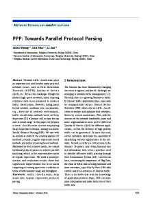
The main characteristic of communication imbalance patterns is its markedly skewed distribution of the communication load across the set of processes. Figure 4 presents a deeper analysis on the type of communication imbalance corresponding to Figure 3b. A distribution of the communication load per process (or rank) is presented in Figure 4a. The ranks have been sorted according to their communication load. The distribution is skewed, showing a few ranks concentrating a big portion of the communication volume. We also present in Figure 4b the Gini coefficient for the distribution in Figure 4a. The Gini coefficient is a measure of statistical dispersion that is usually applied to determine the degree of inequality in a distribution. If ranks are sorted in increasing order according to their communication volume, it is expected that the cumulative share of communication grows steadily as more ranks are considered. Therefore, a perfectly uniform distribution of the communication load would imply that the accumulated communication function F grows with the identity function I. If there is inequality, function F will deviate from the identity and create a gap (shown as a gray region in Figure 4b). The relative size of the gap between F and the identity determines the Gini index. In other words, the Gini index G is defined by the formula: Z Z A , A = (I(x) − F(x))dx, B = F(x)dx G= A+B 100 80
G=0.36
60 40 20 00
20 40 60 80 100 Cumulative Share of Lightest Ranks (%)
(b) Gini Coefficient
Fig. 4: Skewed Communication Volume Distribution. Figure 4b shows the Gini index of MiniAMR is 0.36, a value that attest the highly imbalanced distribution in communication. For comparison, the Gini index of NPB-CG is 0. IV. M ESSAGE -L OGGING P ROTOCOL Message-logging protocols are a promising alternative to provide HPC applications with fault tolerance. The performance overhead of those strategies can be kept low [11], [12], they feature a very efficient energy profile [8], [9], and they make possible to parallelize recovery [10]. To leverage all those features, it is imperative to address the major drawback of message logging, namely its increase in memory footprint. We introduce Memory-Constrained Message Logging (M CML), a generalized message-logging protocol that honors a predetermined memory threshold for the message log and provides a framework to optimize the rollback cost after a failure. M CML aims at reaching a balance by which the message log size growth is kept under control, without sacrificing the advantages of message logging during recovery. The design
of M CML is based on the channel-based view of Figure 1. It combines output-logging and non-logging channels. Message logging of channels in M CML are either active or inactive, i.e. messages from the channel’s source to the channel’s destination are either logged or not, respectively. Initially, message logging is active on all channels. As computation proceeds and the total size of the message log reaches critical levels, M CML chooses channels where message logging is turned off. Otherwise, a regular message-logging protocol will be forced to checkpoint (presumably at a suboptimal frequency) to avoid the memory footprint from reaching unsustainable levels. The downside of M CML is that recovery may require more rollbacks. Different strategies in M CML provide a different tradeoff between memory overhead and recovery cost. A. Algorithm We extend the S CML algorithm of Section II to provide an algorithmic specification of M CML. The details of the protocol are presented in Algorithm 1 and Algorithm 2. The constant T HIS represents the unique identifier of a process. Constant T HRESHOLD is used to represent the maximum size of the message log in process T HIS. The necessary data structures are displayed at the top of Algorithm 1. Function S END M SG and R ECEIVE M SG represent the core of the protocol. We assume these functions are located at an intermediate layer in the software stack, below the runtime system layer, and above the communication network layer. Therefore, once S END M SG finishes preparing a message, it will call N ET S END M SG, which is a low-level function that effectively transmits the message. Function S END M SG first populates the header of the message with the necessary information to generate a determinant at reception. The message carries the determinants accumulated up to that point. Before sending the message, the current size of the message log is checked and reduced if necessary. Function T URN C HANNEL L OG O FF chooses a channel from the communication graph and turns off message logging on that channel. The default strategy chooses the heaviest channel. In addition, all messages to that destination are removed from the message log. Finally, the message is stored only if the logging on that channel is active. On the receiver side, function R ECEIVE M SG first checks whether the message is out-of-order (duplicate or old messages). It then creates a determinant and acknowledges the received determinants from the sender. We must emphasize the two types of determinants. A local determinant is created on a process after a message reception. Those determinants are stored in detBuf and piggybacked on outgoing messages until they are safely stored on other processes. A remote determinant is one created on other process and received with an incoming message. Those determinants are stored in detLog and provided to that process during recovery. The M CML protocol in Algorithm 1 is complemented with functions to handle failures. Function FAILURE reacts to the failure of process Y by providing logged determinants and (possibly) logged messages to Y . If the channel between, say, process Z and Y was not active, process Z must roll back
Algorithm 1 M CML: Memory-Constrained Message Logging
Algorithm 2 M CML Auxiliary Functions
Data Structures: ssn: sender sequence number rsn: receiver sequence number rsnM ap: associative array storing hsender, ssni → rsn inc: incarnation number of current process incM ap: associative array storing hsenderi → inc detBuf : temporary buffer of local determinants detLog: storage of remote determinants msgLog: storage of messages commGraph: graph storing communication volume and channel status 1: procedure S END M SG(msg, target) 2: msg.sender ← T HIS . Populate message header 3: msg.recver ← target 4: msg.ssn ← I NCREMENT(ssn) . Update ssn 5: msg.inc ← inc 6: msg.dets ← detBuf . Piggyback determinants 7: if |msgLog| > T HRESHOLD then 8: T URN C HANNEL L OG O FF(commGraph) . Turn off log on a channel 9: end if 10: if commGraph[T HIS][target].log then 11: msgLog ← msgLog ∪ {msg} . Store message 12: end if 13: N ET S END M SG(msg, target) 14: end procedure 15: procedure R ECEIVE M SG(msg) 16: if O UT O F O RDER(msg) then return . Check for out-of-order 17: end if . messages 18: rsnM ap(msg.sender, msg.ssn) ← I NCREMENT(rsn) 19: detBuf ← detBuf ∪ {hmsg.sender, T HIS, msg.ssn, rsni} 20: detLog ← detLog ∪ msg.dets . Add remote determinants 21: N ET S END D ETACK(msg.dets, msg.sender) 22: P ROCESS M SG(msg) 23: end procedure 24: procedure R ECEIVE D ETACK(dets) . Remove determinants 25: detBuf ← detBuf \ dets 26: end procedure 27: procedure C HECKPOINT( ) 28: E MPTY(detLog, detBuf, msgLog) . Empty logging structures 29: data ← hssn, rsn, rsnM ap, inc, incM ap, commGraphi 30: S TORE C HECKPOINTA ND DATA(data) . Create a restart line 31: end procedure 32: procedure FAILURE(Y ) 33: I NCREMENT(incM ap(Y )) . Update Y ’s incarnation 34: S END D ETS F ROM L OG(Y ) 35: if commGraph[T HIS][Y ].log then 36: S END M SGS F ROM L OG(Y ) . Replay messages 37: else 38: R ESUME F ROM C HECKPOINT() . Message logging to Y was off 39: end if 40: end procedure 41: procedure R ECEIVE D ETS(dets) 42: for all det ∈ dets do . Receive determinants and populates 43: rsnM ap(det.sender, det.ssn) ← det.rsn . rsnM ap 44: end for 45: end procedure 46: procedure R ESUME F ROM C HECKPOINT 47: data ← R ETRIEVE C HECKPOINTA ND DATA() 48: ssn ← data.ssn 49: rsn ← data.rsn 50: A NNOUNCE ROLLBACK() 51: end procedure 52: procedure ROLLBACK(Z) 53: if commGraph[T HIS][Z].log then 54: S END M SGS F ROM L OG(Z) 55: else 56: R ESUME F ROM C HECKPOINT() . Message logging to Z was off 57: end if 58: end procedure
1: procedure S END D ETS F ROM L OG(target) 2: dets ← ∅ 3: for all det ∈ detLog do 4: if det.recver = target then 5: dets ← dets ∪ {det} 6: end if 7: end for 8: N ET S END D ETS(dets, target) 9: end procedure 10: procedure S END M SGS F ROM L OG(target) 11: for all msg ∈ msgLog do 12: if msg.recver = target then 13: N ET S END M SG(msg, target) 14: end if 15: end for 16: end procedure
along with Y . When process Z rolls back, it retrieves the latest checkpoint and announces its rollback. The difference between functions FAILURE and ROLLBACK lies in the fact that the latter does not provide the stored determinants to rolled back processes. A rolled back (not failed) process is assumed to have its determinants available. The recovery process is illustrated in Figure 5.
TABLE I: Main Features of Applications Used in Evaluation.
. Collect all determinants . bound to target . in detLog
. Collect all messages . bound to target . in msgLog
Z
W
Y
X healthy process
rolled-back process
restarted process
Communication not logged
Communication logged
Fig. 5: Rollback Chain in M CML. V. E XPERIMENTAL E VALUATION A. Setup To evaluate the effectiveness of the M CML protocol presented in Section IV, we built a profiling library to explore the communication pattern of MPI applications and understand the benefits and tradeoffs of the algorithm. We used the MPI Profiling Interface to build a communication library that intercepts all communication calls in an MPI application. The library outputs the communication graph of the execution, along with additional information on collective-communication calls. We ran the communication library on a collection of representative applications from several HPC software projects. Table I summarizes the main features of these applications. All these codes use MPI operations for communication and provide the user with a collection of runtime parameters to calibrate the execution. We chose those scenarios in the applications that present communication imbalance, either because of load imbalances or the proper communication pattern of the program. Application/Project
Domain
Problem
FLASH/FLASH Graph500/Graph500 Lassen/ASC MCCK/CESAR MiniAMR/Mantevo MiniFE/Mantevo NPB-MZ/NPB
Physics Graph analytics Physics Neutronics Physics Physics Linear Algebra
Multigrid solver Breadth-first search Front tracking Monte Carlo sim. Adaptive mesh ref. Finite element Block tridiagonal
The experiments were run on Stampede supercomputer at the Texas Advanced Computer Center. Stampede is a 5.168 petaflop computer with 6400 nodes and 522,080 total cores. Each node on Stampede has 2 Intel Sandy Bridge processors for a combined 16 cores, plus an Intel Xeon Phi co-processor.
20 10 20 30 40 Sender Rank
50
60
20 10
low
00
10
(a) FLASH
high
20 10
low
00
10
30 20 10 50
60
low
high
50 40 30 20 10 00
10
20 30 40 Sender Rank
(d) MCCK
20 30 40 Sender Rank
50
60
low
(c) Lassen
Communication Volume (MB)
40
20 30 40 Sender Rank
60
60 Receiver Rank
Communication Volume (MB)
Receiver Rank
50
10
50
30
(b) Graph500
60
00
20 30 40 Sender Rank
40
50
60
high
60
Communication Volume (MB)
10
30
50
50 Receiver Rank
00
40
high
60
Communication Volume (MB)
30
Communication Volume (MB)
40
50 Receiver Rank
Communication Volume (MB)
Receiver Rank
50
high
60
Receiver Rank
high
60
40 30 20 10
low
00
10
(e) MiniFE
20 30 40 Sender Rank
50
60
low
(f) NPB-MZ
Fig. 6: Skewed Communication per Rank Distribution of Applications with Communication Imbalance. Application
Number of Cores
Rank Gini Idx.
FLASH Graph500 Lassen MCCK MiniAMR MiniFE NPB-MZ
256 256 256 256 256 256 256
0.27 0.44 0.35 0.37 0.32 0.28 0.20
Avg. Rollback Set Size (% of |P|) θ = 30 40 50 60 70 57.42 2.34 1.56 1.17 39.45 69.53 60.55
30.08 1.17 1.17 0.39 28.90 47.65 15.62
18.36 0.78 0.78 0.39 14.84 30.86 8.20
12.89 0.39 0.39 0.39 7.81 8.98 3.12
7.42 0.39 0.39 0.39 4.69 2.34 0.39
Avg. Rollback Chain Size (% of |P|) θ = 30 40 50 60 70 0.78 0 0 0.39 0.78 3.51 8.20
0.78 0 0 0 0.78 1.95 3.91
0.78 0 0 0 1.17 1.95 3.12
0.78 0 0 0 1.17 1.56 1.56
0.78 0 0 0 1.56 0.78 0
TABLE II: Effect of M CML on Rollback Effort. The nodes are connected through an Infiniband FDR network. B. Results Figure 6 shows a heatmap representing the data exchange volume in each application. Similar to Figure 3b, the communication matrices are symmetric but present a high variation in the communication distribution. Figures 6a and 6e show strongly defined clusters along the main diagonal, but communication distribution diffuses as we move away from the diagonal. Figures 6c and 6d present imbalanced communication patterns, but with specific zones that clearly concentrate a huge communication volume. Figure 6b highlights a few processes centralizing most of the data exchange. Figure 6f offers a case of a more chaotic communication pattern that leads to prevalent imbalances. Table II quantifies the communication imbalance using the Gini Index of the rank distribution. There is a good spectrum
of values, but in general the numbers in the table are high, which attest for the skewed distribution in the communication volume. Table II also shows the impact of using M CML protocol in reducing the message log. We measured two quantities: average rollback set size and average rollback chain size. The former refers to the total number of processes that must rollback after a single-process failure. The latter represents the maximum depth of the rollback chain. For instance, in Figure 5 the rollback set size is 3, and the rollback chain size is 2. Both quantities are expressed in relative terms to the size of the process set P. Table II measures both rollback set size and rollback chain size based on θ, which represents the threshold used by M CML as a percentage of the maximum message log size in S CML. As expected, higher values of θ fetch better benefits. An experiment using MiniAMR (a single 16×16×16 block per rank) demonstrates M CML weak-scales. Table III presents
the average rollback set size as the program scales from 512 to 4,096 cores. M CML is very effective with θ = 60. Its benefits reduce as the Gini index decreases. Cores
Gini
512 1,024 2,048 4,096
0.30 0.24 0.23 0.17
Avg. Rollback Set Size (% of |P|) θ = 30 40 50 60 70 42.00 59.18 57.42 84.45
29.10 41.50 38.33 47.34
14.45 28.81 24.07 27.68
6.25 16.60 13.23 11.08
1.37 7.32 5.52 3.49
TABLE III: Weak-Scale Experiment. Results from a strong-scale experiment with Graph500 (scale=16, edge factor=16) are listed in Table IV. Ranging from 512 to 4,096 cores, the benefits improve as the communication distribution becomes more imbalanced. At the highest scale, M CML effectively uses a smaller message log with a negligible cost in rollback. Cores
Gini
512 1,024 2,048 4,096
0.27 0.34 0.42 0.51
Avg. Rollback Set Size (% of |P|) θ = 30 40 50 60 70 1.95 0.78 0.39 0.10
0.78 0.30 0.10 0.02
0.19 0.10 0.05 0.02
0.19 0.10 0.05 0.02
0.19 0.10 0.05 0.02
TABLE IV: Strong-Scale Experiment. The M CML protocol allows different strategies to choose the channels on which message logging is turned off. We evaluated two strategies in Table V using FLASH code on 256 cores. The default strategy is called heaviest link first, as it prefers the channel with the highest amount of communication. The second strategy builds a hierarchical clustering of the processes, also called a dendrogram. Channels are chosen based on the clustering, preferring those in the near vicinity. For instance, in a system with 8 processes [0-7], process 5 would prefer to turn off channels to the following clusters with that priority: [4-5], [4-7], and [0-7]. The results in Table V suggest that for an application with communication imbalance, but with a clustered structure, a smarter strategy improves results. From Figure 6a, it is clear that FLASH features clusters of processes and thus a clustering strategy exploits that fact. Strategy Heaviest Link First Hierarchical Cluster
Average Rollback Set Size (% of |P|) θ = 30 40 50 60 70 57.42 53.12
30.08 17.19
18.36 3.12
12.89 0.78
7.42 0.39
TABLE V: Comparison of Strategies to Reduce Message Log. VI. E XTREME -S CALE P ROJECTIONS We use an analytical model to project the performance of M CML at extreme-scale and to run a comparative analysis between S CML and M CML protocols. The model uses theoretical formulations presented elsewhere to estimate execution time [10] and energy consumption [8]. The basic formula
in the model decomposes the execution time into four parts: T = TSolve + TCheckpoint + TRecover + TRestart , and finds appropriate analytical expressions to approximate each part. The model contains several parameters to represent fundamental variables that affect the total execution time of protocols such as S CML. The output of the model is the optimum value of τ , the checkpoint period, for which the total execution time T is minimized. A formula for energy consumption can be derived from the execution time equation by considering the power levels at which each of the parts of the formula executes. A straightforward extension of the base analytical model is used to project execution time and energy consumption of M CML. The extended formula needs the selection of values for the parameters. We chose values based on the available literature [8], [10], and the results of Section V. Table VI summarizes the values of the main parameters in the model. In particular, ω represents the fraction of the optimum checkpoint period (τ ) that is attainable without using M CML. For instance, a value of ω = 0.3 means the system reaches the maximum size of the message log (in at least one process) and it is forced to checkpoint after 0.3τ time units of the latest checkpoint. The underlying assumption is that without M CML, a system using S CML will perform suboptimal checkpointing. Parameter o reflects the portion of the system that is forced to rollback after a crash when using M CML. Parameter
Description
Value
W MS δ R µ φ ω o H L
Time to solution Mean-time-between-failures per socket Checkpoint time Restart time Message-logging slowdown Message-logging recovery speedup Fraction of optimum τ Fraction of recovering processes High power level Low power level
24h 40y 5m 0.5m 1.05 1.2 [0.3-0.7] 0.1 100W 50W
TABLE VI: Values of Parameters of the Model. The model projects a clear benefit of M CML in both execution time and energy consumption when the system scales from 8,000 to 512,000 sockets. Figure 7 shows the relative performance of M CML compared to S CML. The various curves represent different values for ω. In all cases, we assume M CML checkpoints at optimum frequency, while S CML checkpoints at a suboptimal frequency dictated by ω. The relative execution time of M CML compared to S CML is presented in Figure 7a. As the system scales in size, so does the failure frequency (which linearly depends on the number of sockets). The results show M CML can effectively reduce the execution time by maintaining the optimum checkpoint period. The fraction ω has a major impact on performance. At the highest scale, M CML reduces the execution time from 2.7% to 24.5%. Relative energy consumption is shown in Figure 7b. Using M CML provides a reduction from 0.4% to 15.9% at the highest scale. The reduction in energy consumption is not as high as the reduction in time because the downside of M CML
MCML(ω =0.5) MCML(ω =0.4) MCML(ω =0.3)
1.00 0.95 0.90 0.85 0.80 0.75 0.70
8 16 32 64 128 256 512 System Size (thousands of sockets)
SCML MCML(ω =0.7) MCML(ω =0.6)
1.05 Relative Energy Consumption
Relative Execution Time
1.05
SCML MCML(ω =0.7) MCML(ω =0.6)
MCML(ω =0.5) MCML(ω =0.4) MCML(ω =0.3)
1.00 0.95 0.90 0.85 0.80 0.75 0.70
(a) Execution Time
8 16 32 64 128 256 512 System Size (thousands of sockets)
(b) Energy Consumption
Fig. 7: Performance of M CML Protocol at Scale. is to have more processes recovering after a failure. Those processes will consume more energy during a faulty execution. M CML manages to reduce energy consumption thanks also to the reduction in execution time. VII. C ONCLUSION The substantial waste in performance and energy of the classical checkpoint/restart approach has forced the community to look for alternative approaches. Message logging is a promising strategy, but a limiting factor is its potentially high memory consumption. This paper introduces memoryconstrained message logging, M CML, a protocol that realistically assumes each process has a limit to the amount of messages that can be logged. The protocol dynamically adapts to the runtime conditions and reduces the size of the message log by turning off logging on particular channels. The goal of M CML is to keep the memory overhead of message logging at bay, while avoiding a high cost in recovery. The experimental results showed that M CML is very effective in reducing the size of the message log for applications with communication imbalance. In addition, M CML provides a generalized framework to design advanced memory-aware message-logging protocols. ACKNOWLEDGMENTS This work was supported by a machine allocation on XSEDE under award TG-CCR140007. R EFERENCES [1] F. Cappello, A. Geist, W. Gropp, S. Kale, B. Kramer, and M. Snir, “Toward exascale resilience: 2014 update,” Supercomputing frontiers and innovations, vol. 1, no. 1, 2014. [2] M. Snir, R. W. Wisniewski, J. A. Abraham, S. V. Adve, S. Bagchi, P. Balaji, J. Belak, P. Bose, F. Cappello, B. Carlson, A. A. Chien, P. Coteus, N. DeBardeleben, P. C. Diniz, C. Engelmann, M. Erez, S. Fazzari, A. Geist, R. Gupta, F. Johnson, S. Krishnamoorthy, S. Leyffer, D. Liberty, S. Mitra, T. Munson, R. Schreiber, J. Stearley, and E. V. Hensbergen, “Addressing failures in exascale computing,” IJHPCA, vol. 28, no. 2, pp. 129–173, 2014. [3] E. N. Elnozahy, R. Bianchini, T. El-Ghazawi, A. Fox, F. Godfrey, A. Hoisie, K. McKinley, R. Melhem, J. S. Plank, P. Ranganathan and J. Simons, “System resilience at extreme scale,” Defense Advanced Research Project Agency (DARPA), Tech. Rep., 2008.
[4] J. Dongarra, P. Beckman, T. Moore, P. Aerts, G. Aloisio, D. Barkai, T. Boku, B. Chapman, X. Chi, A. Choudhary, S. Dosanjh, T. Dunning, R. Fiore, A. Geist, R. Harrison, M. Hereld, M. Heroux, K. Hotta, Y. Ishikawa, Z. Jin, F. Johnson, S. Kale, R. Kenway, D. Keyes, B. Kramer, J. Labarta, A. Lichnewsky, B. Lucas, S. Matsuoka, P. Messina, P. Michielse, B. Mohr, M. Mueller, J. Shalf, D. Skinner, M. Snir, T. Sterling, R. Stevens, F. Streitz, B. Sugar, A. V. D. Steen, J. Vetter, P. Williams, R. Wisniewski, and K. Yelick, “The international exascale software project roadmap 1.” [5] E. N. Elnozahy, L. Alvisi, Y.-M. Wang, and D. B. Johnson, “A survey of rollback-recovery protocols in message-passing systems,” ACM Comput. Surv., vol. 34, no. 3, pp. 375–408, 2002. [6] G. Zheng, L. Shi, and L. V. Kal´e, “FTC-Charm++: An In-Memory Checkpoint-Based Fault Tolerant Runtime for Charm++ and MPI,” in 2004 IEEE Cluster, San Diego, CA, September 2004, pp. 93–103. [7] A. Moody, G. Bronevetsky, K. Mohror, and B. R. de Supinski, “Design, modeling, and evaluation of a scalable multi-level checkpointing system,” in SC, 2010, pp. 1–11. [8] E. Meneses, O. Sarood, and L. V. Kale, “Energy profile of rollbackrecovery strategies in high performance computing,” Parallel Computing, vol. 40, no. 9, pp. 536 – 547, 2014. [9] M. Diouri, O. Gluck, L. Lefevre, and F. Cappello, “Energy considerations in checkpointing and fault tolerance protocols,” in 2nd Workshop on Fault-Tolerance for HPC at Extreme Scale (FTXS 2012), Boston, USA, Jun. 2012. [10] E. Meneses, X. Ni, G. Zheng, C. L. Mendes, and L. V. Kale, “Using migratable objects to enhance fault tolerance schemes in supercomputers,” in IEEE Transactions on Parallel and Distributed Systems, 2014. [11] E. Meneses, G. Bronevetsky, and L. V. Kale, “Evaluation of simple causal message logging for large-scale fault tolerant HPC systems,” in 16th IEEE DPDNS, in 25th IEEE IPDPS., May 2011. [12] A. Guermouche, T. Ropars, M. Snir, and F. Cappello, “Hydee: Failure containment without event logging for large scale send-deterministic mpi applications,” in IPDPS, 2012, pp. 1216–1227. [13] D. B. Johnson and W. Zwaenepoel, “Sender-based message logging,” in In Digest of Papers: 17 Annual International Symposium on FaultTolerant Computing. IEEE Computer Society, 1987, pp. 14–19. [14] K. M. Chandy and L. Lamport, “Distributed snapshots : Determining global states of distributed systems,” ACM Transactions on Computer Systems, Feb. 1985. [15] L. Alvisi and K. Marzullo, “Message logging: Pessimistic, optimistic, causal, and optimal,” IEEE Trans. Software Eng., vol. 24, no. 2, pp. 149–159, 1998. [16] G. Bosilca, A. Bouteiller, F. Cappello, S. Djilali, G. Fedak, C. Germain, T. Herault, P. Lemarinier, O. Lodygensky, F. Magniette, V. Neri, and A. Selikhov, “Toward a scalable fault tolerant MPI for volatile nodes,” in Proceedings of SC 2002. IEEE, 2002. [17] A. Bouteiller, G. Bosilca, and J. Dongarra, “Redesigning the message logging model for high performance,” Concurrency and Computation: Practice and Experience, vol. 22, no. 16, pp. 2196–2211, 2010. [18] E. Meneses, C. L. Mendes, and L. V. Kale, “Team-based message logging: Preliminary results,” in 3rd Workshop on Resiliency in High Performance Computing (Resilience) in Clusters, Clouds, and Grids (CCGRID 2010)., May 2010. [19] A. Bouteiller, T. H´erault, G. Bosilca, and J. J. Dongarra, “Correlated set coordination in fault tolerant message logging protocols,” in Euro-Par (2), 2011, pp. 51–64. [20] T. Ropars, A. Guermouche, B. Uc¸ar, E. Meneses, L. V. Kal´e, and F. Cappello, “On the use of cluster-based partial message logging to improve fault tolerance for mpi hpc applications,” in Euro-Par (1), 2011, pp. 567–578. [21] E. Meneses, G. Bronevetsky, and L. V. Kale, “Dynamic load balance for optimized message logging in fault tolerant HPC applications,” in IEEE International Conference on Cluster Computing (Cluster) 2011, September 2011. [22] E. R. Rodrigues, P. O. A. Navaux, J. Panetta, A. Fazenda, C. L. Mendes, and L. V. Kale, “A Comparative Analysis of Load Balancing Algorithms Applied to a Weather Forecast Model,” in Proceedings of 22nd International Symposium on Computer Architecture and High Performance Computing (SBAC-PAD), Itaipava, Brazil, 2010. [23] “Graph500 benchmark,” http://www.graph500.org, 2015. [24] P. H. Pisciuneri, S. L. Yilmaz, P. A. Strakey, and P. Givi, “An irregularly portioned fdf simulator.” SIAM J. Scientific Computing, 2013.