A FEM and Image Processing Based Method for Simulation of Manufacturing Imperfections Arshad Javed*, A. K. Sengar and B.K. Rout Department of Mechanical Engineering Birla Institute of Technology and Science, Pilani – 333 031, India *Corresponding Author E-mail:
[email protected] Abstract - Use of appropriate methods to capture manufacturing imperfection at the conceptual stage is a major challenge for the designer and researchers in industry. Imperfections are observed in almost all type of in macro, micro and nano-machining domain of manufacturing process. These imperfections lead to undesirable performance in application phase. In the present work, a simulation based approach to handle manufacturing imperfection is implemented using image processing operators. This method simulates the image of the component due to manufacturing imperfections. The usage of these image processing operators facilitates a realistic simulation of manufacturing errors, in macro, micro, and nano domain manufacturing. The simulated image is further processed for its structural properties i.e. maximum deflection, reactions, Von Mises stress, and change in amount of material, corresponding to its intended application. In order to generate these results based on modified image of beam, the concept of "Solid Isotropic Material with Penalization"(SIMP) is utilized along with 2-D finite element routine. An example of a simple cantilever beam is selected to illustrate the proposed methodology, and the results are analyzed. The present work discusses a simple and easy method to predict the behavior of designed component prior to its manufacturing.
scenario, it is very difficult to produce a precise component. Hence, consideration of imperfection becomes a vital issue. Present work focuses on the simulation issue of geometric imperfection of a structural component. The manufacturing processes considered are, milling for macro, etching for micro and electron beam lithography and laser micromachining for nano domain. To carry out simulation process, image processing operators i.e. dilate and erode are used [5, 6]. Presently, researchers are using these operators for the simulation of geometric imperfections [7], however, the application is limited. In order to use the image processing operators efficiently, it is necessary to know its corresponding effect on the property of the structural component. To fulfill this requirement, the concept of solid isotropic material with penalization (SIMP) is applied. SIMP is a methodology to optimize the topology of a structural component as well as synthesizing a compliant mechanism even at nano level [8, 9]. SIMP applies a particular approach to get the details of structural property of any arbitrary shape using the image of structural component. Based on image processing operator and SIMP, the simulations are carried out and effects on the structural component are recorded. The objective of this work is to explore the behavior of the property of a structural component, over the variation of image processing operators. A methodology is proposed to fulfill the objective. It can be applied to any type of shape of structural component. It will help the designer and practitioners to set a particular value of image processing operator to simulate a real time geometric imperfection.
Keywords: Manufacturing imperfection, Nano-fabrication, Micro-fabrication, FEM, Image processing, SIMP
I. INTRODUCTION Manufacturing errors and imperfection are a common part of any product or component. Imperfections emerged out by various means. One of the approach is to use a very accurate process, where cost and effort increases exponentially. Other approach is to reduce the consequences of manufacturing imperfection, by performance simulation prior to application. By simulating the performance, the parameters of boundary can be adjusted to get the intended results. The imperfections are observed at macro level and also spread across the domain of micro and nano scales. At this level, the manufacturing errors lead to imperfections of the components, which change the property of the component drastically. Thus, the required performance cannot be achieved [1-4]. In such
The manuscript is organized in following manner. In section two, the details of the image processing operators is presented. The approach of SIMP is given in section three. The overall methodology to apply the simulation process is discussed in section four. The details of selected problem and its simulation results are discussed in section five and six respectively. Finally conclusion is drawn.
1
ARME Vol.1 No.2 July - December 2012
Arshad Javed, A. K. Sengar and B.K. Rout
II. IMAGE PROCESSING OPERATORS
are equivalent to an intermediate state between solid or void. The assumed intermediate states are purely mathematical and it cannot be implemented at manufacturing level. To make it feasible, density parameters are penalized using a power-law approach that produces an approximate discrete solution. A very high penalization turns the density parameter near to one or zero that represents empty or solid condition. Usually penalization power is taken as three. This technique is termed as SIMP [11].
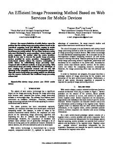
Image processing operators are used for single processing of the original image. There are several image processing operators available to modify or process an image into desired form. From vast ranges of operators, two specific operators are selected i.e. Dilate and Erode, for binary image. This selection is based on their capability to simulate the actual manufacturing imperfections [7]. Dilation (Dilate) allows the image boundary of empty (white) region to expand in filled (black) portion. This makes the total area of empty region to increase. Erosion (Erode) allows the filled image boundary to expand in the empty region. Thus, the total area cover by filled region of the image increases. The effect of Dilate and Erode can be observed in Fig. 1. These operators simulate the imperfections corresponding to milling, etching, electron beam lithography, and laser micromachining. The operators can be tailored by the proper selection of the structuring element (SE) that decides exactly how the object will be dilated or eroded. Based on the suitability to simulate the manufacturing imperfection few are chosen in the present work. These SEs are line, disk, square, and ball (Table I).
In the present work, the SIMP is used in a reversed way. Here the process starts with a given density value, which is generated from the simulation of image. The stepwise methodology of this process is given in next section. IV. SIMP METHODOLOGY The proposed methodology is implemented by creating a MATLAB code. The steps of this process are summarized below. Step 1.
Selection of a structural component (beam).
Step 2.
A black and white image of the beam is created, where black represents the presence of material.
Step 3.
Image is modified using Dilate or Erode operators. It represents the manufacturing imperfection.
Step 4.
The modified image is read and a matrix of its corresponding pixel values is generated.
Step 5.
The values of the pixel matrix are normalized between zero to one. Gray elements are represented by intermediate values.
Step 6.
The elements of the pixel matrix, which are having values equal to zero, are assigned a min value (0.001). It makes valid operations of matrixes while applying FEM. The resultant matrix is called as "density matrix".
Step 7.
Different modulus of elasticity values are generated for each element of density matrix. It is carried our using power law approach of SIMP.
Step 8.
The values of modified elasticity values for the elements are preceded for FEM based routine.
Step 9.
Using FEM, the values of reaction on beamsupports, nodal deflection, and Von-Mises stress are computed.
Fig.1 (a) Original image (b) Dilated image(c) Eroded image
III. SOLID ISOTROPIC MATERIAL WITH PENALIZATION (SIMP) In the present work, the structural property of the component is computed using SIMP approach, associated with finite element method (FEM). In this section, a brief detail of SIMP is presented. Initially, Bendsoe and Kikuchi [10] developed a homogenization approach, which is the basis of the present state of art in SIMP. The problem is worked out in a descritized approach, where the whole design domain is considered element wise. Each element is assigned a density parameter, which expresses the existence of “material” or “no material”. Strictly speaking, this design parameter is the material presence expressed in fractional values for the each element and it is constant within each element. The value of density parameter is relaxed in a continuous interval from zero to one, by inclusion of gray elements. Physically, the gray elements
ARME Vol.1 No.2 July - December 2012
V. EXAMPLE In the present work, a cantilever beam shown in Fig. 2 is selected for the application of proposed methodology. The 2
A FEM and Image Processing Based Method for Simulation of Manufacturing Imperfections
length of the beam is 20 mm, width is 4 mm and the thickness if 1 mm. The beam is having internal curves. The modulus of elasticity and the Poisson's ratio are selected as 200 GPa and 0.3 respectively. At the lower right end of the beam, a load of 10 N is applied as shown in Fig. 3. The simulations are performed on this beam, and the results are provided in the next section.
observed in 5(a). It shows that for SE-4, the mass fraction is having highest and lowest values. For SE-7, the mass fraction is very near to the actual values. The deflection in upward and downward direction can be observed from Fig.5 (b) & (c) respectively. When the load is applied, the curvature of the curved part of the beam is changed and the nodes in that region will have the upward deflection. It can be seen that, deflection in both cases are high for dilated beam. It is due to the removal of material from the beam. This relationship is not direct, as for dilated-SE-5 the upward deflection is increased though the mass fraction is higher for SE-4. For SE-7, the deflections are near to the actual values in both cases. The downward deflection is highest for dilated-SE-4, and lowest for eroded-SE-4. Maximum reaction values at the fixed end of the beam are also simulated for the selected beam, as shown in Fig. 5(d). The reaction is highest for dilated-SE-1 and lowest for eroded-SE-4. The reactions are almost equal to the actual value at SE-7, in both cases. For the failure check, VonMises stress is computed for each case of the beam, as shown in Fig. 5(e). For dilated-SE-1, 3, 6, 7 & 8, it is approaching to the actual value. It is highest for dilated-SE4, where the mass fraction is lowest. Apart from eroded-SE2 & 7, the Von-Mises stress values for all SEs are lower than the actual values. The lowest value is observed at erodedSE-4, where the mass fraction is highest.
Fig. 2 Dimensions of selected beam, in mm
Fig. 3 The corresponding black and white image of the cantilever beam
VI. RESULTS AND DISCUSSION As per the methodology given in section four, the simulations are carried out. The Dilate and Erode operators are set for few SEs which are given in Table I.
In these result, the effect of different SEs can be observed. The highest and lowest effect is made by disc2 and ball1 SE, respectively. Hence, for a fine variation of properties, ball1 SE should be used in simulation and for coarse variation, disc2 SE should be used. It can be seen that the values are in direct relationship with mass fraction, leaving few cases. The reason for this may be the way in which material is dilated or eroded from the beam. In addition, the mirror image property of dilate and erode operators can also be observed. The maximum variation of the mass fraction is also same for the dilation and erosion, i.e. around 9% of the actual value. The obtained values depend on the topology of the beam. However, the observation will be similar among the different properties. The obtained results indicate that the method is beneficial to simulate the manufacturing imperfections efficiently.
TABLE I STRUCTURING ELEMENT TYPES SELECTION FOR SIMULATION
SE No. 1 2 3 4 5 6 7 8
Type Line 1 Line 2 Disk 1 Disk 2 Square 1 Square 2 Ball 1 Ball 2
The actual image of beam (Fig.2) is dilated and eroded, for each SE values. Simulated images are shown in Fig.4. In these images, the effect of dilation (Fig. 4(a)), and erosion (Fig. 4(b)) can be seen with respect to its SE number. In dilation, the amount of material of beam is reduced, while in erosion, the amount of material of beam is increased. The variation in the material of beam i.e. mass fraction, is controlled by the SE parameters. The SE parameters are tuned to produce a particular amount of variation, which are referred from the actual case of imperfections [12]. The variation of mass fraction from the actual one, can be
3
ARME Vol.1 No.2 July - December 2012
Arshad Javed, A. K. Sengar and B.K. Rout
Fig. 5(b) Variation of upward deflection
Fig. 4(a) Dilated images for SE numbers
Fig. . 5(c) Variation of downward deflection
Fig. 4(b) Eroded images for SE numbers
Fig. 5(d) Variation of maximum reaction
Fig. 5(a) Variation of Mass fraction
ARME Vol.1 No.2 July - December 2012
4
A FEM and Image Processing Based Method for Simulation of Manufacturing Imperfections
REFERENCES
Fig. 5(e) Variation of maximum Von-Mises stress
VII. CONCLUSION In any manufacturing process, imperfections are obvious. However, it is imperative to simulate the imperfection before the actual process. In the present work, the imperfection are simulated which are valid for machining, etching, electron beam lithography, and laser micromachining. In this simulation process, imageprocessing operators are used along with SIMP method. The variations among the different SEs are observed for a selected cantilever beam problem. Their effects on beam deflection, reaction, and Von-Mises stress are simulated and analyzed. Present work will be helpful to the practitioner to select a specific SE to simulate the imperfections. This work can be extended for fine examination of each SE in different topologies of structural components.
[1]
Nicolae L. and Garcia E. (2005), Mechanics of Microelectro mechanical Systems, New York, Kluwer Academic, pp. 343-381.
[2]
Daniel R. K., Dominik V. S. and Robert H. B. (2004), “Drastic Enhancement of Nanoelectromechanical-System Fabrication Yield Using Electron-Beam Deposition”, Applied Physics Letters, Vol. 85, pp. 157-159.
[3]
Steve R. and Robert P. (2001), "A Review of Focused Ion Beam Applications in Microsystem Technology", Journal of Micromechanics and Microengineering, Vol. 11, pp. 287–300.
[4]
Hyunseok K., Chulki K., Minrui Y., Hyun-Seok K. and H. B. Robert (2010), “Local Etch Control for Fabricating Nanomechanical Devices,” Journal of Applied Physics, Vol. 108, pp. 1-3.
[5]
William K. P. (2007), Digital Image Processing, John Wiley & Sons.
[6]
Solomon, C. and Breckon, T. (2011), Fundamentals of digital image processing: a practical approach with examples in Matlab, Chichester, West Sussex: Wiley-Blackwell.
[7]
Sigmund O. (2007), "Morphology-Based Black and White Filters for Topology Optimization", Structural and Multidisciplinary Optimization, Vol. 33, pp. 401-424.
[8]
Javed A., Rout B. K. and Mittal R. K. (2007), "A Review on Design and Synthesis of Compliant Mechanism for Microactuation", Proceedings of 2nd ISSS National Conference on MEMS, micro sensors, smart materials, structures and systems, Pilani, India, pp. 110.
[9]
Elesin Y., Wang F., Andkjær J., Jensen J.S. and Sigmund O. (2012), Topology optimization of nano-photonic systems, Integrated Photonics Research, Silicon and Nanophotonics (IPRSN), Theory, Modeling & Simulations I: Numerical Methods (IM2B), Colorado Springs, Colorado.
[10] Bendsøe M. P. and Kikuchi N. (1988), "Generating Optimal Topologies in Structural Design using a Homogenization Method”, Computer Methods in Applied Mechanics and Engineering, Vol. 71, pp. 197-224. [11] Bendsøe M. P. and Sigmund O. (2003), Topology Optimization: Theory, Methods and Applications, Berlin, Springer, 2003, pp. 2-68. [12] Sigmund O. (2009), "Manufacturing Tolerant Topology Optimization”, Acta Mechanica Sinica, Vol. 25, pp. 227-239.
5
ARME Vol.1 No.2 July - December 2012