motor peak currents were matched with the datasheet specifications. .... Competition using Intel atom boards for ... htt
A Final Project Report Submitted to the WPI Robotics Engineering Program
Written and submitted by: WPI-Smart Robotic Prosthetic Hand
Sean Casley Thanacha Choopojcharoen Adam Jardim Deniz Ozgoren Project Advisors: Professor Cagdas Onal Professor Taskin Padir
Date: April 21, 2014
ABSTRACT This project involved the design and development of an operational first prototype for the IRIS platform – an anthropomorphic robotic hand capable of autonomously determining the shape of an object and selecting the most appropriate method for grabbing said object. Autonomy of the device is achieved through the use of a unique control system which takes input from sensors embedded in the hand to determine the shape of an object, the position of each finger, grip strength, and the quality of grip. The intended use for this technology is in the medical field as a prosthesis, though the hand could also be adapted to work on other robot platforms as a versatile gripper. The advantage of our system as a prosthesis is that its autonomous functions allow the user to access a wide variety of functionality more quickly and easily than similar, commercially available products.
ii
ACKNOWLEDGEMENTS - Worcester Polytechnic Institute (WPI) for the use of their laboratories and manufacturing facilities. -WPI Robotics Engineering Program including Joe St. Germain, Tracey Coetzee, Nidhi Diwakar, and all other students and faculty who supported our project through their efforts and advice. -Cagdas Onal and Taskin Padir for their guidance throughout the entire project, and for generously donating their time, experience, and resources to help us achieve our many ambitious goals.
iii
1
Contents
ABSTRACT .............................................................................................................................................................. ii ACKNOWLEDGEMENTS ......................................................................................................................................... iii 1
INTRODUCTION ............................................................................................................................................. 1
2
RESEARCH ..................................................................................................................................................... 3 2.1
Prosthetic devices .........................................................................................................................................3
2.2
Non-anthropomorphic prosthetic devices ....................................................................................................5
2.3
Anthropomorphic Prosthetic Devices ...........................................................................................................6
2.4
Sensing Technologies ...................................................................................................................................6
2.5
Human Hand Anatomy .................................................................................................................................7
2.6 Object Recognition .....................................................................................................................................10 2.6.1 Appearance-based Object Recognition .................................................................................................11 2.6.2 Feature-based Object Recognition ........................................................................................................14 3
PROJECT SOLUTION ..................................................................................................................................... 18 3.1
Objectives ...................................................................................................................................................18
3.2
Finger Design ..............................................................................................................................................18
3.3
Palm and Thumb Design ............................................................................................................................21
3.4
Forearm Design ..........................................................................................................................................24
3.5 Electronics ..................................................................................................................................................26 3.5.1 Actuating Fingers ...................................................................................................................................26 3.5.2 Controlling Fingers .................................................................................................................................27 3.5.3 Embedded Object Recognition ..............................................................................................................28 3.5.4 Interfacing with User .............................................................................................................................30 3.5.5 System Integration .................................................................................................................................30 3.6 Object Recognition .....................................................................................................................................34 3.6.1 Hough Transformations for Generic Object Recognition ......................................................................36 3.6.2 SURF Detection for AR Marker Tag Recognition ....................................................................................41 3.6.3 Software Implementation ......................................................................................................................41 3.7 Control Architecture Analysis and Design ..................................................................................................42 3.7.1 Nomenclature ........................................................................................................................................42 3.7.2 Scheduling ..............................................................................................................................................45 3.7.3 Force Detection using Series Elastic Actuator .......................................................................................46 3.7.4 Position control for moving each fingers ...............................................................................................50 4
PERFORMANCE EVALUATION ...................................................................................................................... 52 4.1
Evaluation in overall aesthetic design ........................................................................................................52
4.2
Evaluation in overall movement of the hand .............................................................................................52
iv
4.3 Evaluation in object recognition .................................................................................................................52 4.3.1 Hough Transformation for Generic Objects...........................................................................................52 4.3.2 SURF Detection for AR Marker Tags ......................................................................................................53 4.4
Evaluation in electrical hardware ...............................................................................................................53
5
RESULTS ...................................................................................................................................................... 55
6
TECHNICAL DOCUMENTION......................................................................................................................... 59 6.1
Finger (Mechanical Drawing) .....................................................................................................................59
6.2
Palm (Mechanical drawing) .......................................................................................................................59
6.3
Forearm (Mechanical drawing) ..................................................................................................................59
6.4
pcDuino ......................................................................................................................................................60
6.5
Microcontroller Board Specifications .........................................................................................................60
7
PROJECT EXECUTION OVERVIEW ................................................................................................................. 62
8
RECOMMENDATIONS & FUTURE WORK ...................................................................................................... 62
9
CONCLUSION ............................................................................................................................................... 62
9
REFERENCES ................................................................................................................................................ 63
10 APPENDICES ................................................................................................................................................... 64 Appendix A: Systems Engineering ...........................................................................................................................64 Appendix B: Decision Flowchart ..............................................................................................................................66 Appendix C: Force Sensor Weighting Scale Example ...............................................................................................67 Appendix D: Final Linkage System ...........................................................................................................................68
v
1 INTRODUCTION Every year there are about 6,000 (McGimpsey) upper limb amputations in the United States alone, leaving tens of thousands of individuals disabled and deformed. Aside from the discomfort caused by curious stares from onlookers, these injuries can greatly hinder an individual’s ability to perform even basic daily tasks. Past attempts at a replacement limb, referred to as a prosthetic, have included mechanical hooks and pincers that grant the user some functionality, but lack in versatility. More recent products such as the i-Limb and bebionic prosthetic hands have brought the technology far closer to giving amputees back the range of ability they once had, but users still find interfacing with these devices to be overly complicated, and limiting (“i-Limb Ultra”, 2014) (“The Hand”, 2014). Additionally, these new devices come with a much higher price tag than their predecessors; an expense that many potential users feel is not worth the increase in capabilities. The development of a highly versatile upper body prosthetic device that addresses the issues of cost and usability of today’s commercially available prostheses would enable the technology to far exceed the potential of its alternatives. This project provides a proof of concept prototype for the IRIS platform - an anthropomorphic robotic hand capable of determining the most appropriate grip for grasping an object and executing that grip with minimal human input. Through the implementation of advanced sensing technologies into the device, this project aspires to develop a prosthetic hand that is as natural and easy to use as a person’s organic extremity, without the need for invasive surgical procedures. The issue of usability will be primarily addressed by the implementation of a digital vision subsystem imbedded in the prosthetic that will allow our device to determine the shape of the object the user is reaching for. The hand will then be able to take this information and automatically adjust to an appropriate grip. The end goal is that the user will only need to reach for an object and tell the device when to close. The process of selecting and executing a particular grip pattern will be taken care of automatically, much like what is done naturally in our subconscious. The issue regarding cost will be addressed thought the use of inexpensive materials such as plastics, and low cost manufacturing techniques such as laser cutting and 3D printing. Though this report places emphasis on the implementation of the IRIS system as a prosthetic device, the technology can also be applied as a versatile gripper for modular robot platforms. By using 1
our system, a robot would be able to grab a wide variety of objects without any major alterations to the robot. All that would be needed is a custom adaptor to mount the IRIS to the robot leads connected to the grab and release input ports of the IRIS controller. Additional circuitry could be included to allow the IRIS to communicate with a robot platform via more traditional means such as USB.
2
2 RESEARCH Before diving straight into the development phase, background research was conducted to ensure we were making well informed decisions. To do this, we looked into the following topics:
Prosthetic devices Non-anthropomorphic prosthetic devices Prosthetic hand with myoelectric sensor Sensing technologies Object Recognition
2.1 Prosthetic devices Within the field of medicine, a prosthesis is defined as an artificial device that replaces a missing body part lost through trauma, disease, or congenital conditions. A prosthesis that replaces a part of the arm between the elbow and wrist is called a transradial prosthesis, also referred to as a “BE” prosthesis for below-elbow. These devices can be functional or simply cosmetic depending on their intended use. An amputee who does a lot of manual labor and needs a device that is durable, dependable, and strong may choose to have a simpler prosthesis such as a hook. On the other hand, an individual who is willing to sacrifice functionality for a prosthesis that looks more natural may choose to get a cosmetic prosthesis, also known as a cosmesis, like the one shown below in Figure 2-1.
Figure 2-1: Personalized Cosmetic Prosthetic Hand by Sophie de Oliveira Barata
Functional transradial prostheses are available in two main types, body powered and externally powered. Body powered prosthetic limbs are controlled using cables connected to a harness or strap mounted elsewhere on the user’s body. When the user moves their body in certain ways they pull on 3
the cables to cause motion in the prosthesis. The simple nature of these devices makes them very light but also means they are typically incapable of executing complex tasks. A common terminal device for body powered prostheses is a pincer like mechanism called a split-hook, illustrated in the diagram below, though many other’s exist for more specific tasks like fishing or cooking ("How Prosthetic Limbs Work.", 2014)
Figure 2-2: Typical Body Powered Transradial Prosthesis
Externally powered prostheses are devices that receive their power from sources other than the user’s body. Usually electrically powered, modern devices are able to utilize multiple electric motors and other electrical components to achieve more complex grips and functionality than can be accomplished with a simple body powered device. The additional use of onboard microcontrollers and sensors allow for these prostheses to be controlled in a variety of ways. One common technique for controlling an externally powered prosthetic device is the switch control method. This method allows the user to move their prosthetic device by toggling switches or buttons. A user can toggle the switches using another part of their body such as their opposite shoulder, or with the remaining muscle in their residual limb. Since these devices are typically able to perform such a wide variety of grips, the user can often use different sequences of switch toggles to alternate between different grip modes. Another, more advanced method of controlling an externally powered prosthetic device is through the use of electrodes. When placed on the surface of the skin, these sensors are capable of detecting the small electrical signals generated by muscle contractions in the user’s residual limb. In most applications additional software and circuitry are used to make these analog devices behave like 4
switches. The user is then able to control their device in a similar manor to the switch control method. Devices that utilize this technology are called myoelectric prostheses. Some examples of commercially available myoelectric prosthetic limbs are the Bebionic hand and the i-Limb. Each device is an advanced externally powered prosthetic limb and is currently considered top of the line in commercially available transradial prostheses ("Myoelectric Prosthetics.", 2014).
2.2
Non-anthropomorphic prosthetic devices One of the most common non-anthropomorphic terminal devices used on upper body
prostheses today is the split-hook; a simple device primarily comprises of two hooks which are jointed together at the base by a hinge. This design enables the hooks to open and close in a pincer like fashion allowing for basic grip functionality. The curved shape of this prosthesis offers a fair bit of functionality as well, so long as there is a hole, handle, or divot for the hook to fit into. These devices are typically body powered though externally powered versions are available. Relative to other more versatile prosthetics, what the split-hook lacks in functionality it makes up for with durability and a low cost ("Prosthetic Devices.", 2014).
Figure 2-3: Common Split-Hook Terminal Prosthetic Devices
Custom Non-anthropomorphic prostheses are also developed for more specific tasks such as cooking or fishing, or even for sports like basketball, climbing, or golf. It is not uncommon for an individual to own several functional prostheses intended for different tasks as well as a cosmesis for social events. 5
2.3 Anthropomorphic Prosthetic Devices On the other side of the transradial prosthetic spectrum are devices such as the i-LIMB and the bebionic hand. This new generation of externally powered robotic prostheses combines functionality with a natural, anthropomorphic appearance. The inclusion of an opposable thumb and four independently actuated fingers allows for not only more human like movement but also a wider range of grip patterns. Sensors in the device allow for system feedback resulting in better performance, and in some cases even user feedback through the use of lights, vibrating motors, or other interfaces.
The prostheses are typically myoelectric. To operate the device the user preforms combinations of muscle contraction that will initiate one of the preloaded grip patterns. The number of available patterns can vary from 14-24, depending on the model.
Figure 2-4: Anthropomorphic Prosthetic Hands Showing bebionic (left), i-LIMB Ultra Revolution (center), i-LIMB Cosmetic Cover
Though these devices have a lot of advantages over earlier, simpler prosthetics, the additional weight caused by the onboard electronics can cause them to be uncomfortable to use for long periods of time. Another drawback of these devices is their high price. Peaking at about $100,000 after fitting and training, it is difficult for many potential users to afford one even with insurance.
2.4 Sensing Technologies For directly measuring force at the contact point, Force Sensitive Resistor (FSR) can be attached with additional hardware such as low-pass filter and amplifier. Because of its low cost and low precision, FSRs are mostly used for detecting pressure for buttons in portable electric devices.
6
One of more precise force sensing device was developed by Matthew M. Williamson at Massachusetts Institute of Technology. Williamson introduced Series Elastic Actuator (SEA), which corporates series elastic element in order to improve the stability in force control. There are many ways to implement SEA based on the motion of the actuator. Even though precision in force sensing is much higher than FSRs, implementation of SEA normally requires lots of space. Because of low-band width and high force sensing precision, SEA is used in Rethink Robotics’ Baxter Robot for sensitive manipulation.
2.5 Human Hand Anatomy Since the IRIS hand was designed to be anthropomorphic, a fairly extensive understanding of human hand anatomy was required. Here we will go over the terms for the different bone and muscle groups as well as their primary function and physical aspects.
The human hand is comprised of 29 major and minor bones a good number of which make up the wrist, 29 major joints, and 34 muscles 18 of which are located in the forearm. The hand comprises of only 22 degrees of freedom; three flexion and one abduction in each finger and thumb, and an additional two between the metacarpals of digits four and five that allow the palm to curl. All these joints are shown in Figure 2-5 below.
7
Figure 2-5: Hand Joint Diagram
The wrist and forearm add an additional three degrees of freedom; rotation about the x,y,z axis originating from the center of the wrist.
The naming scheme of these bones follows a fairly basic naming convention. Those bones which make up the compound wrist joint are known as carpels. The bones that make up the palm of the hand are called metacarpals. The bones that make up the fingers are known as phalanges. The phalange at the base of the finger connected to the knucle is referred to more specifically as the proximal phalange. After that comes the middle or intermediate phalange, and finally the distal phalange makes up the tip of the finger. The thumb is different in the way that it does not have an intermediate phalange, causing the distal phalange to be connected directly to the proximal phalange ("Hand.", 2014).
Each finger is capable of flex, extend, abduct, and adduct thought the flexion and relaxation of multiple muscle groups. The fingers themselves do not contain muscles but are attached by tendons to the muscles that power them located in the palm and forearm. Muscles located in the palm are referred to as intrinsic muscles and comprise of the thenar (muscles that power the thumb), hyposthenia (muscles that power the pinky), the dorsal and palmar interossei (muscles located between the 8
metacarpals which respectively abduct and adduct the middle three fingers), and the lumbrical muscle (muscles which flex the metacarpophalangeal joints and extend the interphalangeal joints). Muscles which have their bellies located in the forearm are referred to as extrinsic and comprise of the large strong muscles that enable the middle three fingers to flex and extend.
For this project we decided to base the dimensions of our device off of the average human male hand dimensions. This was for two reasons, the first being that males tend to have larger hands then females which gave us more room to use for our prototype and second by using the average we would be able to maximize the number of potential users of the device when we are ready to go into our first round of testing. We were fortunate enough to find a paper written on a study in which the hand x-rays of 66 individuals, ranging in age from 19 to 78, were studied and their bone measurements taken (BURYANOV, 2010). The averages of these measurements were calculated and published in their report. The most relevant data form the report is included in the figure and table below.
Figure 2-6: Human Hand Bones Labeling Scheme for Table 2-1
9
Table 2-1: Average Human Hand Bone Lengths
Though the values used on our device are not the same as the averages included here the measurements do fit within one standard deviation.
2.6 Object Recognition In order to add intelligence to our system, we deduced that the use of a camera and object recognition is the most direct way of understand the world around our device. Object recognition is an objective in the larger research field of computer vision. Computer Vision is the use of computers to visualize, interpret, process, and understand the world through images to determine some numerical or relatable information from the image in order to make decisions. The study of computer vision began in the early 60’s for the understanding of man-made environments. Despite the nearly 50 years since its beginnings, computer vision still proves to be a difficult and complicated task. However, it is a widely and actively researched field, especially in the last decade, which has allowed for many advancements and even further research into more practical applications of computer vision.
In the field of computer vision, object recognition is one of the more commonly researched tasks. Object recognition is the identification of specific or key objects in the image by locating features unique to those objects. Human beings have little difficulty identifying specific shapes and images despite partial obstruction of the object, angled or faraway view, or objects presented at an irregular perspective. However, object recognition is still challenging to emulate in a computer. The major difficulty lies in our lack of knowledge on how human beings store memory of, identify, and search for objects in our vision. Because this is such a challenging task in particular, many methods for identifying objects have been researched in the past. These methods largely fall into two categories: Appearancebased object recognition and Feature-based object recognition.
10
2.6.1
Appearance-based Object Recognition Appearance-based object recognition is the use of example images of an object in order to
identify the object in question. Approaches that fall under this category often do extensive processing of the image in order to reduce the noise and unnecessary information in the image. Edge matching and use of a model base are two widely used examples of appearance-based object recognition. 2.6.1.1 Edge-Matching Edge-matching is the use of edge detection techniques to find edges in a 2D image. Once edges have been identified, they compare the identified edges to the edges in the example. Then, the relationship between these two edge groups is measured in order to make decisions on how to identify the object in the scene. Depending on the variance between images, the algorithm must be robust enough to correctly identify a range of possible perspectives, positions, and orientations of the object. More specifically, before identifying an object in an image, the image is reduced to a series of edges that indicate the division between two distinct areas in the image. Then the processed image is compared to a series of images containing possible orientations and views of the object in question, multiple objects, or different objects. Then the best image that matches the current image is selected with some quantifiable score relating the similarities of the current image and the selected example image. From this example image and the similarity score, decisions can be made to identify the object in the original image.
This method can be broken down into three major parts. The first task is to detect the edges in the current image and example images. The second task is to relate these edges to the edges in each example. And the third task is to consider which example image provides the best score relating the two images. A common algorithm used for detecting edges is the Canny Edge Detection algorithm. This algorithm, developed 1986 by John F. Canny, is used to detect a variable range of edges in an image. The algorithm can be essentially described as follows:
1. Filter the image of noise a. In order to reduce noise and unnecessary information, Gaussian filters are used to “blur” the image. This allows the image to be more quickly and easily processed. 2. Determine the intensity gradient
11
a. Because an edge can point in any direction in an image, filters are used to identify likely gradient edges that are horizontal, vertical, and diagonal. 3. Use non-maximum suppression (“Edge-thinning”) a. In order to determine the boundary between two areas of the image, pixels are given a gradient threshold relating it to the pixels around it. Pixels that are distinctly directed similarly to the pixels around it surpass the threshold. Pixels that do not surpass the threshold are reduced to a value of 0, indicating that it does not appear follow the general direction of the pixels around it. 4. Tracing edges and hysteresis thresholding a. Through the gradient intensities identified in steps 2 and 3, the pixels with a high gradient intensity are identified as starting points for edges. Pixels with a lower gradient intensity with directions similar to nearby pixels of higher gradient intensities are used to bridge the gap between the higher gradient intensity pixels to create the edges. This method of having a higher and lower bound for thresholds is called hysteresis thresholding. These edges can be traced throughout the image until the entire image consists of either edge pixels or non-edge pixels, typically shown as a completely black pixel. An example of Canny Edge Detection can be seen in Figure [] below.
Figure 2-7: An example of the Canny Edge Detection algorithm
As you can see in the above figure, the original image, shown on the left, has been processed to contain only the major edge lines that surpass the thresholds defined in the Canny Edge Detection algorithm. The processed image on the right can be compared to similarly processed example images containing multiple views and perspectives of one or more objects. A probability of similarity between 12
the test image and an example image is found using a probability distribution of distance from edge to edge in the images. The collective probability distribution of each edge in the test image to each edge in the example image serves as a score to rate the similarities between the two images. A greater probability denotes a potentially greater chance of correctly identifying the object in the test image as the same object in the example image. By comparing the scores of each example image, a best match can be found, containing the greatest perceived likelihood of containing the same object.
This algorithm can very efficiently identify a comparison between two images. Because many steps are taken to process and minimalize the image prior to doing the comparison, the efficiency of this algorithm is dependent on the thresholds used on the Canny Edge Detection algorithm. Stricter thresholds reduce the number of edges that qualify as acceptable, which in turn simplifies the comparison and reduces the operation time of the algorithm. However, tightening these thresholds too much can cause the object to be potentially unidentifiable. Depending on lighting conditions and specific operating environments that the system is working in, thresholds must be tuned to efficient and effective. Tuning these values properly is critical to an efficient use of this algorithm. This is because the edge-detection process of the algorithm is the most computationally expensive because of its dependence on the dimensions of the image and the number of potentially acceptable edges. 2.6.1.2
Use of a Model Base The use of a model base is similar in implementation to edge-fitting. However, model base
analysis works best with a 3D image. The general strategy is to use some form of 3D imaging technology to obtain a 3D view of the object(s) in question. Then, unidentified objects or shapes that deviate from some known or probabilistic pattern are isolated as potentially identifiable objects. These objects are isolated from each other and individually compared to known 3D models of objects in a model database. Objects that closely match the form and shape of an identified 3D model in the database are categorized as that object. As an example, the PR2, a research robot built and developed by Willow Garage, commonly uses a Tabletop Object Recognition package that employs model database analysis. The PR2 is equipped with a Microsoft Kinect sensor, which houses an RGB camera, a depth sensor, and an infrared projector. Using this device, the PR2 can acquire a 3D image of the world before it. The Tabletop Object Recognition package is used primarily for identifying objects on a flat tabletop-like surface. Objects that protrude from this surface are isolated from the table surface. These objects are one-by-one compared 13
to objects in the 3D model database using eigenvectors to determine position and orientation of the object. Objects with a high similarity to known 3D models are compared until a certain similarity threshold is passed. Once this happens, the object is identified as the same 3D model it with which it was matched. However, this method does not work well with objects of an irregular shape or objects that do not match the known database. This method can be a rather effective solution to the object detection. Its effectiveness is limited by the number and variety of object models stored in the database, the thresholds used to compare objects meshes, the sensing capabilities of the 3D camera hardware and software, and the processing power of the device that drives it. Also, it can only operate in specific environments that allow for better segmentation of potentially identifiable objects. Additionally, 3D cameras are often computationally expensive to operate at a useful frame rate, requiring a computer with more significant processing power. However, within it’s ideal environment and given the proper harder, with objects that do exist in its database, this system can reliably identify the object as well as determine its position and orientation relative to the camera.
2.6.2
Feature-based Object Recognition Feature-based Object Recognition is the identification of objects without the use of example
images and templates, but rather using known or identifiable features unique to each object. This method is largely used with distinctly unique object whose features allow for the objects to be easily distinguished from each other. These unique features are used to search the test image. Perspective and rotational transforms are commonly used to increase the likelihood of finding these features. Many methods exist for identifying the object: edge-detection, corner detection, Hough transformations, other feature detector algorithms, and many more. In this section, Hough transformations and the SURF feature detection algorithm will be discussed. 2.6.2.1
Hough Transformations Hough transformations, originally invented in 1959 by Paul Hough, are feature extraction
techniques used to identify geometric shapes and lines from imperfect occurrences in an image. For example, when given an image, Hough transformations can be used to identify all straight lines in the image when given the correct parameters for the scene. These parameters can include the tolerances between slopes of lines, the adjacency of qualifying points, and the frequency of lines in a similar area in 14
the image. However, Hough Transformations can not only be used for lines (in their most basic instance), but also for circles and ellipses. By tuning the parameters in each case, instances of the desired shape or line can be detected, quantified, and measured.
This method is commonly used along with an edge-detection algorithm (similar to the Canny edge-detection algorithm discussed previously) in order to simplify the image and reduce noise. However, with all noise-reduction and image simplification algorithms, the loss of important information is always uncertain. Thus, Hough transformations work to group edges, points, or blobs into common artifacts. This is done through an explicit voting procedure by which the number of points, edges, or blobs that comprise a single object out of a selection of other potential objects is selected.
Simply, put, a collection of two-dimensional points can be linearly fit to a number of potential lines or edges. However, some of these lines contain more points than others. Lines that consist of more points, or have points with a lesser average closeness to that line than the others, are selected and added to the collection of lines.
These potential lines are detected by analyzing each point. By selecting a point, all adjacent points within a specific range are considered to be on the current line along with the previous points. Points that more accurately fall along the slope of a previously defined line grant a higher score to that potential line. Lines with a higher score hold a greater weight when determining the likelihood that a line continues when analyzing the subsequent adjacent points.
Using this method, lines can be identified as vectors along with their angle, length, and start and end points.
The method is similar with the detection of circles. By analyzing the positions of points adjacent to other points, potential locations for the center of a circle can be identified. Groups of points that fall along a common edge of a suspected circle can be used to identify the location of the center of that circle. The more points that fall along the edge of that circle increase the probability that that circle exists. Circles with a probability exceeding some threshold are identified.
15
The effectiveness of Hough Transformation algorithms is determined, like the others by the parameters supplied to it. Tightly constrained parameters defining the length of vectors, their angle tolerance relative to other vectors, and their distance to other potential vectors can drastically change the computation time, accuracy, and usefulness of this solution. Constraints that are too loose will identify fewer potential vectors or shapes than desired, often grouping too many vectors or shapes together or not identifying them at all. Constraints that are too tight will identify more objects, but in greater frequency and each with a much smaller probability of presence in the scene. This additionally increases the computation time of this algorithm considerably, as it continues to cross reference the likelihood of previously identified features as being connected to the currently identified feature.
Additionally, the computation time and accuracy of these transformations can be greatly affected by the amount of pre-processing done to the image before performing the transformations. Using an algorithm like Canny Edge Detection can greatly simplify the image and reduce computation time. However, if the edge detection is not parameterized properly, then the Hough transformations because even less useful, often not properly detecting features from the misidentified edges. 2.6.2.2
SURF Detection SURF (Speeded Up Robust Features) Detection, developed in 2006, is a derivative of the SIFT
(Scale-Invariant Feature Transformation) detection method developed in 1999. SURF detection works to detect similarities between two images by identifying unique features. Reference images are supplied, and the unique features are extracted. These features are then searched in the test image independent of the poses of the features in the image. The invariance of pose and scaling creates a very exceptional use of this technique, which allows the reference image to be identified in the test image along with its location in 2 dimensions, its potential distance from the camera, and its rotation and angle relative to the frame of the image.
Features are identified in the reference images by performing a series of Gaussian functions and detecting the differences following each subsequent Gaussian transformation. Areas that contain little to no change in appearance following each transformation are not considered as features in the reference image. Areas that demonstrate considerable contrast are blurred again in order to further determine the likelihood of features being present.
16
These features, once identified in the original reference image, are searched for in the test image. Hough transformations are used (in a manner described similarly before) to determine potential clusters of features. Clusters of a specific feature with higher probabilities (determined by their location relative to other clusters of specific features) are granted a higher weight and likelihood of being present. The greatest set of clusters, with a higher probability relative to each other cluster, is used to identify the object’s presence and orientation in the image. Additionally, if the reference is image is scaled to a known size, the size of that reference image in the test image can be used to determine its distance from the camera.
From this method and the use of reference images, SURF detection can be used to identify known objects or images within other scenes. When compared to SIFT detection, SURF is much more robust and quick. This is largely due to the use of reference images to reduce computation time and increase the understanding of desired features. This method is useful for identifying complex flat images with great accuracy. However, it is not capable of understanding the 3D shape of objects given its 2D reference images. The object can only be identified given the specific angle and positioning in the reference image. For example, it can only understand a single perspective of a cube and has no understanding of what is on the other side of a cube. As such, without another reference image to fully describe the other side of the cube, it would not be able to properly identify it. In essence, this algorithm is heavily dependent on the presence of comprehensive reference images.
17
3 PROJECT SOLUTION Our solution for the previously mentioned problem is a smart robotic prosthetic hand. The device will be anatomically similar to that of the average American male hand and be able to grasp complex shapes. The intelligence of hand will be attained from basic object recognition for quick identification of generic objects. With this added intelligence coupled with a dexterous prosthesis, we aim to simplify the user interface for amputees and ultimately increase their quality of life.
3.1
Objectives The systems engineering approach identified stakeholders and, in turn, needs. These needs were
combined and converted into a step-by-step general process which we call our objectives. The completion of the following objectives signifies the finished needs in the scope of our project. 1.) 2.) 3.) 4.) 5.) 6.)
3.2
Design and create a prosthetic device for anthropomorphic actuation Identify sensors for object recognition Design and create a system that can automatically detect the environment Integrate the prosthetic device with object detection system Write software to operate the prosthetic with non-predetermined object Demonstrate assisted control through use of sensor and software
Finger Design An important element in our anthropomorphic prosthetic hand design was the development of four
human like fingers. In order to maintain an anthropomorphic appearance the fingers not only needed to look human but also move in a natural, human like way. After extensive observation of hand motions, methods for grasping everyday objects, and anatomical restraints we discovered a common curling behavior that allowed the fingers to securely close around objects of varying sizes and shapes. The challenge however was developing a mechanism that could reproduce this motion and still fit within a casing that was no larger than the average male finger. The design also needed to be durable enough to withstand the rigors of daily use. Before any major design work was done we first explored a couple options of how to achieve the desired finger motion. Based on our own thoughts and some preliminary research we came up with two possible methods. The first method involved the use of cables that would be routed though the segments of the finger and anchored at the tip. The cables would be routed in such a way that pulling on
18
one would cause the finger to curl. This is similar to the way muscles and tendons actuate our natural fingers. The second method utilized a series of inverted four-bar linkage systems imbedded in the finger segments themselves to produce the same curling method. Below is a table of the pros and cons we discovered for each method. Cable system Pros: Cons:
Fewer necessary moving parts Simpler design Fewer Materials Low Cost
Cable can stretch over time Routing may be difficult Possibly more friction
Linkage System Pros: Cons:
Low friction Rigid bodies will not stretch More accurate position control Simple design
Lots of moving parts allows for more points of failure Could take a while to find the ideal link length Link length will differ in every finger
Table 2: Pros and Cons of cables and Linkage System
After weighing each option we decide to use the linkage system. Though it is comparatively more complex and slightly more expensive we believed that the cable routing would be too difficult to work with and the friction it would cause in the system would lead to problems when moving the fingers. We also believed that the rigidity in the linkage system would allow for more accurate approximations of the fingertip location which would improve our motion control. There was also the concern that in order to fit the cables inside the fingers we would need to use such thin cable that it would be too weak to handle the forces acting on the finger and would break. A basic illustration of the linkage system is shown below in Figure 3-1. A more detailed image of the final linkage design can be found in Appendix D of this report.
Figure 3-1: Finger Serial Inverse Four-bar Kinematic Linkage System Diagram
19
Once the proper link lengths had been determined we were able to design a finger mechanism capable of following the desired path. It comprised of six main parts; a tip, two middle segments, a base segment, and two cross bar segments which completed the four-bar mechanism. Our thought process for manufacturing was that the two cross bar segments could be laser cut out of a sheet of acrylic and the rest of the pieces could be 3D printed, and later injection molded. Our first design, shown later in Figure 3-2, was constructed in Solidworks. The first cross link ran through a hole cut out of the solid base piece connecting the middle links to the knuckle. The second cross link ran in between the middle links connecting the base segment to the tip segment. Finally, the two middle segments sandwiched the other two segments, competing the assembly. Unfortunately, the design was rejected for several reasons:
The solid base piece would be too difficult to later make using injection molding The open middle segment would allow for items to get caught inside the finger Relying on the friction of the press fit axles to hold the middle segment together would be too unreliable It failed to meet aesthetic necessities Acrylic cross links were not strong enough to handle minimal allowed forces put on the finger
Figure 3-2: First finger Design
20
Our second iteration was able to address most of the issues we had had with our initial design. To address the perceived difficulty of recreating the base segment using injection molding we decided to split the base segment of the finger into two parts, each side of which could be easily made and screwed together into one piece. This also made inserting the cross bar into the base segment much easier. The middle components were also redesigned to touch at the middle when put into place. The pieces would later be glued together to prevent separation. The Tip was also slimmed down to be more anatomically accurate. For this iteration, we used delryn for the crosslinks instead of acrylic which made the fingers able to handle much greater forces. Unfortunately, we did not feel this design was still not anthropomorphic enough so a few more alterations were made and we finally developed our third iteration which included more anthropomorphic curves and a rubber tip on the end of the finger which improved grip and had a more natural shape. The third design was manufactured on an Objet 3D printer using their veroWhite Plus material. Both our second and third designs can be seen in Figure 3-3.
Figure 3-3 Finger Design Iterations Two (Top) and Third (Bottom)
3.3
Palm and Thumb Design The next important part that had to be designed was the thumb. Fortunately, the linkage mechanism we developed for the fingers to give them a natural curling motion was able to be integrated into the thumb with only a few alterations. The challenge with the thumb then became the design of the powered compound joint at the base of the thumb that allowed it to bend and move in opposition to the fingers. Since we knew there would be limited space in the palm for a motor, we designed the joint to contain the motor which powered the opposing 21
motion of the thumb to be inside the joint segment itself and the shaft of the motor would extend out into the body of the palm. An image of the thumb connected to the compound joint is included below in Figure 3-4.
Figure 3-4: Thumb and Compound Joint
The palm was the final piece of the hand that we designed since it was the component that all other parts would be mounted to. The Palm was designed with five main goals in mind:
1. 2. 3. 4. 5.
Must be able to have the thumb mounted on it Must be able to have the fingers mounted on it Must be able to have the camera mounted in it Must be able to allow the actuation system to reach the fingers Have an anatomically accurate size and shape to the average male hand
22
Figure 3-5: Palm Design
The palm was manufactured like most of our components out of veraWhite Plus on an Objet 3D printer. It was designed to be manufactured in two pieces to make it easier to access the camera and other components housed inside the hand. The camera for the device sits roughly centered in the bottom of the palm and peaks out through a window to detect the objects the user reaches for. The thumb assembly can be easily slid in and out of the bottom segment of the palm after the top is removed. For ease of access and repair, the “knuckles” for the fingers components were designed to be separate components form the palm. The interior of the palm is open to allow for the cabling to pass through.
23
Figure 3-6: Knuckle
3.4
Forearm Design When designing the forearm, there are many things to consider. Primarily, the size constraints
for the proposed system restrict us from using large motors and springs and sensors. Secondly, the shape must be similar to that of the average male forearm. Thirdly, the form must be strong enough and large enough to not only house the motors, cables, and springs, but to also make routing, calibration, and assembly easier. Given that this piece contains the majority of the electronics as well as the transmission system, the design must be incredibly compact.
The forearm consists mainly of three separate sections. These include the wrist/spring module, the transmission/routing module, and the electronics module.
The wrist/spring section of the forearm is mostly hollow and contains two acrylic sheets. The first acrylic sheet is used to separate the tubing and cabling from the palm into manageable paths for the series-elastic actuation system. There must be ample spacing between the springs in order for them to stretch and slide past each other, yet be compact enough to fit within the arm. The cables that connect to the springs are then separated via the second acrylic sheet from the second part of the forearm.
24
The second part of the forearm is used to house the motors, spools, and potentiometers. The transmission system must be compact and easily assembled in a way that allows for routing of the cables to the first part of the forearm. The motor mounts must be strong enough to withstand the tension of the cables and springs as generated by the forces on the fingers and the motors. Additionally, there must be ample room in the forearm for tubing and cables to move and slide back and forth. All the motors are secured on the bottom half of this segment and supported by an acrylic sheet that runs across the top with holes for potentiometers and the motors. This acrylic sheet helps reduce the stress on the motor mounts while simultaneously providing a surface for placing the pcDuino mini-PC platform.
The final part of the arm is used almost exclusively for storing electrical circuits, the Arduino microprocessor, and the remaining half of the pcDuino. It is primarily a hollow space with two shelves for mounting electronics. There is also a cover to enclose the remainder of forearm. The image below shows the final design.
Figure 3-7: Rendering of the forearm
25
3.5 Electronics The system level electronics were designed in order to: 1) Actuate the fingers 2) Control the fingers 3) Embed the object recognition in the system 4) Interface with the user 5) Integrate the system together For the initial product development, priority was given to off-the-shelf components for faster prototyping and replacement of parts. This allows design changes to be made more flexible, and allows modularity for components. Although individual parts were not designed and made in more compact form, size was taken into consideration in design as well. Other factors like power consumption, performance and price were given lower priority at this point of the design. 3.5.1
Actuating Fingers After calculation of required torques and speed for fingers, commercially available motors were
compared for the final selection. The main goal was to find a motor that didn’t require a design of a gearbox - which would need extra space in the hand - and was to find a motor small in size while providing the required torque and speed. Additional factors were cost, voltage requirements, lead times, and weight.
Pololu micro metal gearmotors, with 125 oz-in torque and 32 rpm, were chosen as the motors for the fingers as they are very tiny yet powerful enough for the requirements. A feature that was beneficial was that Pololu offers many different versions of the same motor package with different gear reductions. This allows easy modifications in the design when needed. For instance if there are more friction in the system than expected, higher torque version can easily be swapped, or different fingers can use different motors. Additionally, price tags of these motors are low, which made them an even better option.
Next step was to drive the motors. As the required current and voltage to run these motors are much higher than a typical microcontroller can supply, a motor driver is needed as an interface between the microcontroller and the motors. Compared to ESC, Brush DC motor drivers from main supplier companies such as Allegro Microsystems, Texas Instruments and Freescale Semiconductor were listed and then compared, as they are relatively cheaper for same purposes. These drivers come with dozens of options for industrial applications such as serial communication options, different packaging, low 26
power options and sleep modes. However the main priority was given to output voltage and current capabilities as they are the requirements to drive the motors. Additionally, drivers with fewer pins were considered for simplicity in wiring in the system.
DRV8835 from Texas Instruments, a dual lot voltage H-Bridge IC, was finally chosen for having the capability of driving 2 motors at once with only 12 pins while being able supply the required RMS and peak currents. Interfacing this circuit is easier as well and additionally, after the selection, it was found that Pololu sells the breakout boards for these ICs in a very small size, which made them even easier to use and test.
Figure 3-8 Motor Driver and Micro-gear Motor
3.5.2
Controlling Fingers For position and speed control, the system needs joint angle information. The most convenient
way to achieve it is to directly attach an encoder or a rotational potentiometer directly to the shaft of the rotating joints. Encoders are digital sensors and provide incremental data. The main benefit from the use of encoders is that they can make full 360 degree rotations without any physical limitations. On the other hand, calibration of these might be a challenge as they don’t provide absolute joint angles. Conversely, potentiometers are generally limited from full rotations. However, as full rotations aren’t needed for this project, and these potentiometers provide absolute analog values, rotational potentiometers were selected as the sensors.
The main challenge in selecting a potentiometer was the size constraint. Databases of main suppliers like DigiKey were searched in order to find small enough potentiometers to be embedded inside the joints. Finally, a hollow D-shaft potentiometer from Panasonic with a 343 degree rotation range was selected to be used in the project.
27
Figure 3-9 Hollow Shaft Rotary Potentiometer
Additionally, force control for the fingers, by design, required measurement of motor shaft angles as well. The same potentiometers were decided to be used for simplicity in design. Spools and mounts were specifically designed for these potentiometers. 3.5.3
Embedded Object Recognition In order to embed object recognition on-board rather than tethering the hand to an external
computer through cables, miniPC platforms were compared. These platforms are Linux computers which run embedded versions of operating systems like Ubuntu, and have computer-like features like fast CPU and HDMI connections. The main consideration was given to processing speeds, graphics, and the amount of RAM. Other factors included price, size, storage and I/O interfaces. A final decision was made to select the pcDuino, which has a 1GHz ARM Cortex A8 CPU and 1GB DRAM which is higher than its competitors. Additionally it had Arduino-like features that allow access to GPIO like UART, PWM and ADC.
Figure 3-10 Embedded Linux Computer – pcDuino
After the selection of the embedded PC, different options were considered for camera for the object recognition sensor. The camera needs to communicate with the pcDuino, needs to be compatible with the selected software, and needs to provide enough optical detail about the environment. Initial work has been done to create a custom PCB and putting a small camera module in it for achieving small size. However, it has been decided that the level of complexity in interfacing with camera modules and transferring them to pcDuino was out of the scope of the project, which led to the design choices to be made on camera packages with built-in communication interfaces like USB. Further selection and 28
comparison was made with priority on size, optical detail, price and compatibility with pcDuino. Final choice was made on Logitech C525 Webcam which has 8MP of photo resolution, pcDuino compatibility via USB, manual and autofocus features, and small size factor. In order to fit the camera inside the palm, the external cover of the camera was removed.
Figure 3-11 Camera and its circuitry
29
3.5.4
Interfacing with User Current myoelectric hands in the market interface with sensors that incorporate
electromyography (EMG) to read muscle signals. Users select grips, open and close hand by flexing and relaxing their muscles in the arm. Although this project uses object recognition to simplify the user interface, muscle signals are still necessary for telling the hand to open and close. However this method is complex with many companies and research institutions actively working on them. For this reason it was decided to not include EMG sensors at this stage of the project, but leave expandability in terms of connections in the microcontroller to incorporate them in the future.
Additionally the focus in design of this project is interacting with objects as seamlessly as possible. For this reason only a single button is used if needed for advanced modes, similar to Apple’s iPhone Design. One main use for this button would be to activate teach-mode, where the user is able to introduce hand a new object and how it is held. This way, the user is able to make modifications to the hand’s configurations without the need of a smartphone or a computer connection. Consequently, in order to prevent errors in reading the button, the button was debounced with an RC circuit.
Furthermore, to let the user know about some information like low battery or when an object is successfully detected, an LED is used for visual feedback on the surface of forearm, and a vibration motor is used for tactile feedback.
3.5.5
System Integration In order to bring all the components together electrically and under software, a single
microcontroller was decided to be used as the computation brain and the low level controller. Although the pcDuino is capable of handling both high level and low level tasks, it was left as a co-processor for handling object recognition with the camera. This way, the system is more modular, where a different smaller or faster co-processor can be replaced for the project without affecting the rest of the system.
This main board doesn’t require high RAM or GPU power but it has to keep up with controlling all the components. The factors in choosing the microcontroller were: -
It must be capable of supporting most common used hardware interfaces such as UART, SPI, I2C preferably including PWM and ADC on board having enough GPIO pins for the project It must be small while incorporating other electrical components like voltage regulators. support for the product 30
-
Price The capability to run the control loop at 50Hz The capability to store the code Available to buy on demand
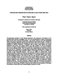
For their proven record in the market, and big support by the community, Arduino was chosen as the platform for the project, which provided many different microcontrollers in different packages. This is also beneficial for modularity, where a different product line can easily be swapped with the same code conveniently. Consequently, the choices were narrowed down to the Arduino Pro Mini that uses ATmega168, which runs at 16MHz, has 6 PMW outputs, 8 analog inputs, is small in size, and includes all the previously listed hardware interfaces while leaving room for extra GPIO connections. It additionally has on-board regulator, which regulates power and prevents the circuit from failing to short circuitry.
Figure 3-12 Arduino Pro Mini (16MHz)
The overall system can be contains 5 main parts: 1. Main board 2. Actuation 3. Sensing 4. Object Recognition 5. User Interface
31
Figure 3-13 Electrical System Diagram
32
1. Main board: This consists of the main controller (Arduino Pro Mini), a multiplexer, and the PWM driver. As many potentiometers are needed to be interfaced with the ADC, the final design uses an external multiplexer that channels potentiometers through the Arduino’s internal ADC one at a time. It supports up to 16 analog sensors to be read. Similarly, the PWM driver is used to increase the number of PWM pins, which are needed to control the motor drivers. The current PWM driver uses 12 channels and supports up to 16 channels.
Each of these circuits is powered by 5V signal level power. Multiplexer is controlled by 4 digital outputs from Arduino for channel selection, and 1 signal wire is input to Arduino’s analog input for reading. PWM driver is controlled from Arduino by 2 I2C wires, and communication protocol is achieved by the libraries provided by the driver.
Figure 3-14 Multiplexer and PWM Driver
2. Actuation Each motor driver is powered by both 5V signal power and 9V motor power. Additionally 4 PWM lines are interfaced from the PWM driver per motor driver to control the hbridge in phase-enable mode. This way 2 motors are controlled per motor driver with 2 power wires per motor connected to the motor driver.
As the motor drivers are the most sensitive circuits on the hand, they are ordered with their breakout boards from Pololu with regular spaced pinouts. They are wired with female to male header inserts so that they can be replaced anytime. 3. Sensing All potentiometers are wired with ribbon cables to save space. They share a common ground and signal power. Each potentiometer’s signal line is connected to the corresponding multiplexer channel.
33
4. Object Recognition A camera is connected to the pcDuino for communication and power via USB. The pcDuino is powered by 5V signal power and connected to the Arduino with 2 wires for communication via UART. 5. User Interface Button, LED, and vibration motor are all low power components, thus all are interfaced directly with Arduino without external power connections. Motor and LED is controlled by PWM pins and button is read with a digital input pin.
3.6 Object Recognition As discussed in previous sections, there are many methods and algorithms for determining the object. These methods include, but are not limited to, Edge-Matching, Hough Transformations, and SURF detection. However, the most object recognition techniques are not effective in all situations. In this section, the mechanical and software limitations of the system, including limitations imposed by the environment, will be discussed, as well as how they relate the earlier mentioned object recognition techniques.
The system is primarily limited on a hardware level. Because the device we propose is rather small and compact, we are limited in the type of camera that can physically fit within the confines of the palm. Because the camera is smaller, we are forced to use either more advanced cameras or use cheaper, more accessible cameras.
These kinds of cameras may include the cameras used in
smartphones and small digital cameras as well as typical computer webcams. The frame rate, image quality, and compatibility with OpenCV are also factors that determine what object recognition methods would be most effective. Because these are all specifications unique to each camera involved, we are limited in what algorithms can be used. Furthermore, cameras that are not compatible or usable with the pcDuino computing platform are not acceptable either.
The system is also limited on a software level. Regardless of the camera chosen, assuming OpenCV can interface with it, there are processing limitations for our mini-PC platform. The pcDuino, while it is a PC running lubuntu, is not an overly sophisticated computing device. It has limited memory and processing power, both of which slow down even some of the most common tasks for a standard PC. Because of this, any algorithm chosen must be both memory-efficient and fast. Algorithms that 34
consume extensive processing resources cannot be considered for this device. Similarly, algorithms that are time-dependent and take more than five seconds to process are not satisfactory options. Additionally, any algorithms that can simplify or expedite the image processing are preferable.
Of the previously mentioned algorithms and methods, we can determine how each method would work towards determining the object in front of the device. The methods presented earlier are the use of edge-matching, Hough transformations, and SURF detection.
Edge-matching object detection would require a comprehensive set of reference images to compare with the image from a 2D camera. This appearance-based object recognition method would be useful in tightly constrained situations where the view of the object does not change and is not likely to vary significantly. For this method to work, the object would have to be viewed via the camera from a predictable perspective. Then, the algorithm would simplify the scene to its most essential edges and compare them to each of its reference images. Images with the highest scoring match (above some threshold) would be selected as the image containing the matching object. Additionally, any amount of preprocessing of the image to simplify the number of edges would greatly increase the likelihood of finding a match. A flow-chart detailing the process can be seen below.
Figure 3-15: Flow Chart of Edge-Matching Algorithm
Hough Transformations are also a viable option for performing object recognition. Depending on the level of preprocessing done to the image, Hough Transformations, specifically for line detection, can be very useful. However, this requires an understanding of the objects that are to be identified. If a full understanding of the objects as a series of lines and edges is obtained, then the objects can be view 35
from any angle. Additionally, a high level of preprocessing can be done for this. Color segmentation for specifically colored objects as well as Canny Edge Detection can be used. However, the use of color segmentation does make the scene somewhat lighting dependent. Thus a range of colors should be expected and tuned for a variety of lighting situations. A flowchart detailing a full process of identifying an object via Hough Transformations is shown below.
Figure 3-16: Flow Chart of Hough Transformation Algorithm
Finally SURF detection for 2D images is analyzed. SURF works best with flat objects, being able to detect the single face of the object while still remaining scale independent. The process is rather simple as there are several examples of SURF working with streaming video performing object detection on the fly. No pre-processing is necessary for this. However, because SURF works best with flat objects, the lighting in the scene is very important. The light that catches that flat object, despite being perspective and scale independent, can cause the flat object to be “washed out” for unreadable. The process of analyzing the scene would simply be to open a video stream from the camera and to run the SURF algorithm with the stored images for searching.
Given these three methods, including any preprocessing strategies that might be used, our proposed solution is a combination of all three. Because our device must be able to detect generic shapes and AR tags, the primary use of Hough Transformations and SURF detection is valuable. 3.6.1
Hough Transformations for Generic Object Recognition Because the generic objects are all an identifiable shade of green, a certain level of color
segmentation can be performed in order to pull the object out from the background. Then, Canny Edge Detection can be performed much more quickly and efficiently. This further allows the Hough Line transformation to be sped up and be more directly applicable to the object of interest. Because each of these algorithms increases the efficiency and accuracy of the algorithms before it, this strategy allows the device to quickly and predictably detect the objects.
However, several things important things must be understood and several calibrations must be performed before the system can recognize the object. These include a proper calibration of the 36
segmenting colors, the dimensions of the image from the camera, and the number of Hough transform lines we should expect.
In order to decide the proper colors to segment from the background, many tests were performed in many lighting conditions to detect the particular shade of green of the generic objects. These lighting conditions testing in high and low light conditions, testing color and brightness in direct light and in a shadow, and the angle of the lighting and reflectivity. In order to test the range of colors, we grab a series of images in these various light conditions then measure the RGB values for the colors we desire. From these tests, we determine an average color range that includes both direct light and in shadow shades of green.
To isolate the green objects from their background, we must parse the image on a pixel level. For each pixel in the image, we identify its RGB values are within the range we defined earlier. For all pixels that do not fit into that range, we set that pixel’s RGB values to 0;0;0 (black). This color segmentation algorithm’s efficiency and speed is directly related to the size of the image. However, since we are working with 640 by 480 pixel dimension, the calculation is fairly simple and quick to compute.
Once the color segmentation has properly separated the green objects, a proper calibration of how to reduce these objects to their edges. By defining the specific color contrast ranges that define an edge, the algorithm is more likely to identify the major edges without any unnecessary information. This was done by repeatedly running the standard Canny Edge Detection algorithm on the color segmented images (which were taken in a variety of lighting scenarios) and modifying the Gaussian transform parameters. Because the object in question is already isolated in the image, little adjustment is required to acquire the desired output from the Canny Edge Detection.
After the image is reduced to its major edges, running a series of Hough Line Transformations on the image will generate a set a vectors that define the object’s edges. These vectors must be extensively tweaked and manipulated in order to achieve the desired output. Ranges of angles, lengths, and the proximity of pixels to one another all greatly define the abundance of vectors and their usefulness. Ideally, each straight edge in the image will be defined by a single vector that covers its whole length. By manipulating the parameters to the Hough transformation function, we can achieve this result given 37
our knowledge of the camera’s dimension and distance that the device’s camera will be placed away from the object.
Given the object is now reduced to a list of vectors that are fully described and able to be analyzed, we must define each object we wish to observe. The objects we wish to observe are a cube, a cylinder, and a sphere. A table containing the information on each shape can be seen below. Table 3-3: Generic Object Descriptions
Shape Cube Cylinder Sphere
Contains Straight Lines Yes, between 4 and 9 Yes, between 0 and 4 No
Contains curved edges No Yes Yes
Number of parallel line groups