platform prior to the real robot: a hardware-in-the-loop (HIL) simulator. HIL simulators ... hosting a simulation environment such as SRSim, USSRSim,. Webots, or ...
Australasian Conference on Robotics and Automation (ACRA), December 2-4, 2009, Sydney, Australia
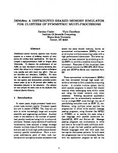
A Hardware-in-the-Loop Simulator for Distributed Robotics Ritesh Lal and Robert Fitch ARC Centre of Excellence for Autonomous Systems Australian Centre for Field Robotics (ACFR) The University of Sydney, NSW Australia {r.lal, rfitch}@acfr.usyd.edu.au Abstract Developing planning and control algorithms for distributed robotic systems involves implementing complex asynchronous algorithms on embedded hardware platforms with limited computational resources. The ability to efficiently validate such algorithms in hardware is critical, yet challenging due to their decentralised nature. We propose the use of hardware-in-the-loop simulation as an intermediate step to improve the process of performing such validation. We present the design and implementation of a custom hardware-in-the-loop simulator consisting of 27 embedded units with wireless communication and a special gateway device for interfacing with a desktop computer. We also present two case studies that illustrate the use and benefits of this system.
1
Introduction
We are interested in developing planning and control algorithms for distributed robotic systems. One class of particular interest is self-reconfiguring (SR) modular robots [Fitch and Butler, 2008]. These are versatile robots that can dynamically adapt to their environment through reconfiguration of constituent modules. Another class of interest is large teams of mobile robots. Conducting research in distributed robotics often requires custom embedded hardware development in addition to software development. It is important to validate algorithms in hardware both to test assumptions made in algorithm design, and to better inform hardware design of resource requirements. We would like to be able to perform such tests quickly in order to speed up the development cycle. We would also like to be able to test the same generic algorithm on various hardware platforms in an efficient manner. The challenge in development for concurrent systems is that it is difficult to observe the full state of the system at any given time [Rosa et al., 2008]. Two common methods are to use serial ports to transmit state information to a terminal, and
Figure 1: 27-node decentralized hardware-in-the-loop simulator. to use individual LEDs attached to the embedded platform as a sort of binary “printf.” These methods are feasible for small systems, but not practical for systems with more than 15 to 20 modules [Butler et al., 2002]. Our proposed approach is to employ an alternative methodology where implementation is performed on an intermediate platform prior to the real robot: a hardware-in-the-loop (HIL) simulator. HIL simulators are frequently used in cases where performing tests with actual hardware is prohibitively dangerous or expensive. HIL simulators have also been investigated in the case of mobile robots systems [Hu, 2005]. The idea is to execute computation and communication tasks on the embedded hardware, but to simulate actuation and sensing. Common simulators such as Stage [Gerkey et al., 2003] can be integrated, or specialized simulators such as SRSim (a self-reconfiguring robot simulator) can be utilized [Butler et al., 2004]. The technical challenge is to design and build the
Australasian Conference on Robotics and Automation (ACRA), December 2-4, 2009, Sydney, Australia
computation, communication, and memory components of the actual system being simulated, augmented by additional specialised functionality to support concurrent debugging. In this paper, we present the design of a custom HIL simulator for distributed robotics. We designed and constructed 27 embedded units, shown in Fig. 1, that can control either real or simulated robot platforms. The embedded units include small graphical displays to facilitate debugging, and can be programmed wirelessly as a group. We have found this approach to be a powerful infrastructure that supports the implementation of complex asynchronous algorithms. The paper is organised as follows. We discuss related work in Sec. 2. We then present an overview of our system architecture in Sec. 3, followed by details of our embedded hardware in Sec. 4 and of our method for over-the-air programming in Sec. 5. Case studies that illustrate usage of the system are presented in Sec. 6 and we conclude in Sec. 7.
2
Related Work
Work closely related to this paper includes HIL simulators in other domains, software-only simulators, and distributed debugging research. We discuss these results in this section.
2.1
Simulators and HILS
There are a number of simulators currently available for robotics research. Popular open source examples are Player/Stage [Gerkey et al., 2003], Gazebo [Cyberbotics, ¨ [Browning and Tryzelaar, 2003]. Com2009], and UberSim mercial simulators include Webots [Webots, 2009] and Microsoft Robotics Studio. Simulators specific to SR robots include USSR [Christensen et al., 2008] and SRSim [Butler et al., 2004]. Simulators such as Stage also have the ability to simulate real and simulated robots creating a robot-in-the loop simulator; [Hu, 2005] describes one such implementation. HIL simulators are common in the aerospace and automotive industries( [Gholkar et al., 2004]). Their use is motivated by the need to perform extensive testing while minimizing the risk of damaging expensive equipment [Cosic et al., 1999]. Some example implementations are given in [Gietelink et al., 2009; Cai et al., 2009; Gholkar et al., 2004]. Ours is the first application of HIL simulation to self-reconfiguring robots.
2.2
Distributed Debugging
Distributed systems present challenges stemming from synchronization or concurrency. Debugging techniques used by researchers currently include custom print statements [Dao et al., 2009] and live debugging tools [Liu et al., 2008]. Our systems supports debugging using a graphical display per node for custom print statements that are transparently time-stamped and logged to non-volatile storage. Debugging normally requires iteratively reprogramming modules, which is quite simple for small numbers but becomes increasingly time consuming for tens of modules or
more. Two implementations that seek to address the reprogrammability problem are [Bordignon et al., 2009] and [Zhang et al., 2002]. Our system used over-the-air unattended reprogramming, described in Sec. 5.
3
System Architecture Overview
Our HILS implementation consists of three distinct hardware subsystems shown in Fig. 2: 1) the set of embedded units that execute decentralised algorithms; 2) the desktop computer hosting a simulation environment such as SRSim, USSRSim, Webots, or Player/Stage/Gazebo; and 3) a gateway device that implements a communication link between the other two subsystems. The desktop subsystem is responsible for simulating actuation and sensing; the embedded units implement “real” computation, communication, and memory. The gateway accepts actuation commands from embedded units using wireless communication, and forwards these commands to the desktop via a serial (hardwired) connection. Wireless communication is implemented with off-theshelf, 2.4GHz, ZigBee ([ZigBee Alliance, 2009]) hardware modules from Digi ([Digi International, 2009]). ZigBee was chosen primarily because of its mesh-networking capabilities. Detailed discussion of the choice of ZigBee over other possibilities such as Bluetooth is provided in our previous work [Fitch and Lal, 2009], which describes an earlier iteration of the embedded subsystem. Wired communication between the gateway and the desktop is implemented over a serial (RS232) link using a simple custom protocol. Finally, the gateway device facilitates the important convenience of programming the embedded units wirelessly. This process is known as over-the-air (OTA) updating. OTA update functionality allows remote firmware updates and is described in Sec. 5. Technical details of the embedded units are presented in the following section.
4
Embedded Hardware and Software
4.1
Hardware
The embedded hardware of the distributed platform comprises 27 identical units. The hardware block diagram is given in Fig. 3 and shows the main components and their interconnections. A photograph of a single unit is shown in Fig. 4. We describe system components and performance in the following subsections. Basic Components Our embedded platform design is based on the ST Microelectronics ARM Cortex-M3 CPU [STMicroelectronics, 2009]. Some important features of the STM32 are listed below: • • • • • •
CPU: ARM 32-bit Cortex-M3, 72MHz Memory: 512kB Flash, 64kB RAM Serial: UARTs, SPI, I2 C High Speed: USB, CAN Timers: 11 timers with PWM, 1 RTC Other: 12-bit ADC, FSMC, 12ch DMA
Australasian Conference on Robotics and Automation (ACRA), December 2-4, 2009, Sydney, Australia
Simulated Actuation and Sensing
serial
ZigBee Gateway
wireless
Embedded Units
Desktop Simulator
Decentralized Planning and Control
Figure 2: System block diagram.
Figure 3: Embedded system block diagram. The CPU is run at a clock frequency of 48MHz. Clock frequency is adjustable using the Phased Locked Loop. A higher clock speed demands higher power consumption so 48MHz was chosen not only for power saving, but also to have the additional speed as reserve if required. The PCB is a 4-layer board using mainly surface mount components. All onboard devices run on a +3.3V supply provided by the LM3102 switch-mode power supply (SMPS). The LM3102 is a 1MHz, wide input voltage (4.5-42V) buck regulator delivering up to 2.5A. The design incorporates power supply filters to suppress any voltage ripples generated by the SMPS. The NAND Flash, part number A25L16PUM-F, is a 16Mbit device with 256-byte pages and 256 pages per block. The interface to the NAND flash is SPI.The primary purpose of the NAND flash is to store copies of the firmware images that are downloaded either via the OTA drivers or the bootloader; this is discussed in Sec. 4.2. Some memory blocks can also be dedicated to save configuration information. A micro-SD card slot is also included and is intended for storage of large files such as lookup tables and data logs. At the present time, capacities of up 16GB are readily available in the micro-SD format. The high speed serial interfaces include the USB interface, the v2.0 CAN bus and also 1Mbit capable UARTs. Of interest
Figure 4: Single embedded unit. for our application is the CAN bus. The CAN bus is fault tolerant differential bus and is intended to be the local bus of the robot. The CAN bus is useful for expansion purposes in the case of interfacing multiple processors within a module. The PWM outputs consist of seven dedicated channels driven by the STM32’s timers. All channels are capable of 16-bit PWM. There’s also an 8-way selector on one of the PWM outputs, which allows us to multiplex this output to control multiple motors. Finally, there is a 20-way auxiliary connector on the PCB exposing several general purpose input-outputs (GPIOs). Some of these are capable of accepting analog inputs. We also have 2 TTL level serial ports and one I2 C interface available here. The majority of inputs to the STM32 are 5V tolerant, allowing interfacing with 5V logic devices without additional logic level translation. Support for Development and Debugging The OLED (Organic Light Emitting Diode) screen is a 1.5”, full-color, 128x128 pixel display made by [Univision Technology Inc., 2009] and uses the SSD1339 controller from Solomon Systech. The display can be controlled via an 8-bit parallel interface or a 4-wire SPI. The STM32 can support either mode using the FSMC controller or one of the SPI ports.
Australasian Conference on Robotics and Automation (ACRA), December 2-4, 2009, Sydney, Australia
A low profile dip-switch on the PCB allows selection of the communication mode. Using an on-board display means that unit activity and status can be observed immediately, instead of having a serial terminal open for each module. This capability is invaluable in any distributed system especially during development. Furthermore, we are using a logfile on the microSD card to (transparently and with timestamps) record all information printed by the embedded units. There is also an onboard joystick (5-way switch: up, down, left, right & center positions) providing additional user interaction to the display. The joystick is used to “scroll through” lines of text. Power Consumption The board consumes 115mA @5V = 575mW. From [STMicroelectronics, 2009], [Univision Technology Inc., 2009] and [Digi International, 2009] typical power consumption per module is given in Table 1. Other components, eg. RS232 level convertor, leds also consume power and considering losses in the LM3102, the measured power consumption is close enough to the expected value. At the present time none of the low power modes of MCU or the ZigBee Modules are being used. However, we have achieved standby power of as low as '10uA in other designs using the STM32. Device MCU OLED ZigBee
Power @3.3V 28.6mA 35mA 40mA
Conditions All peripherals on Maximum rating Tx/Rx
Table 1: Embedded hardware power consumption.
4.2
Software
The embedded software consists of a bootloader, real-time operating system (RTOS), device drivers, peripheral drivers, and application code. The embedded software stack is given as Fig. 5. We describe these components in this section. Build Environment and Bootloader We are using the Rowley Associates Crossworks for ARM development environment. The CrossWorks IDE can be run under Linux or Windows and integrates a C/C++ compiler, editor, simulator and on-chip debugging via JTAG. Also included in the package is the (royalty free) Tasking RTOS. Programming the STM32’s on-board flash is accomplished using either JTAG or the serial bootloader that comes preloaded on the MCU. Programming via USB is also possible but requires additional software on both the PC side and the embedded side to realize. For our application, we have developed a custom bootloader. The bootloader executes first on reset or power-on and then jumps to the main application when complete. The bootloader is a separate program and is flashed onto the MCU
Figure 5: Embedded software layer stack. via JTAG. Bootloader responsibilities include: 1) Y-Modem functionality to download new firmware to NAND Flash; 2) update the STM32 Flash if newer firmware is available on NAND Flash from either a Y-Modem download or OTA update; and 3) jump to the main code. An entire page is allocated on the NAND Flash to save information for the bootloader. This information includes unique ID, last update time, and start sector for the newest firmware. Fig. 6 shows the bootloader logic. This figure shows that the NAND Flash Status page is used as a nonvolatile storage for bootloader operations. Real-Time Operating System We use the Crossworks Tasking Library (CTL) RTOS for our embedded units. CTL is a pre-emptive multitasking OS with concurrency support. There are four main threads in our software system design: 1) idle; 2) display; 3) communication; and 4) application. The idle thread is the lowest priority thread and runs when no other thread is requesting the CPU. Its main tasks are controlling LED blinking, push-button monitoring, and other housekeeping functions. The display thread is responsible for setting up the display and all drawing operations. All graphical widgets are created in this thread’s context as well. Widget handles are used by other threads to update values. The widget class then generates an event requesting repaint for the display task. The display task will then repaint the widget when it next runs. A message queue (stl list) is implemented as part of the display thread to buffer write requests. Two comms threads handle all communications to and from the ZigBee device. Each interacts with other threads via (synchronised) FIFO queues implemented as an STL list. The receive thread waits to continuously receive data from ZigBee device and processes the various events that are generated. A transmit thread waits for messages to be posted into its queue and sends them in FIFO order. Once a message is sent, the transmit thread waits for a delivery acknowl-
Australasian Conference on Robotics and Automation (ACRA), December 2-4, 2009, Sydney, Australia
display. Implemented widgets interact with the display through this class. There are three widgets being used. The text widget occupies most of the display area. This widget outputs text onto display with the specified color and implements automatic scrolling; text lines scroll up as lines are added to the bottom. The application layer calls a printfDisp(colorCode, “text”) function to use the text widget. The joystick inputs are passed into this widget to enable manual text scrolling. The area on the right of text widget is reserved for status icons. These indicators are very useful when simulations are running as they reflect the number of received/transmit messages currently in the respective queues and also their maximum values. The NAND-Flash-wrapper hides the hardware specific requirements from the main application. The microSD-wrapper not only manages the card specific operations but also implements a FAT12/16/32 compatible filesystem. We have used the open source Embedded File System Library (EFSL) for this, modified to enable DMA read and write, support for SDHC cards, and support for multiple read/write commands. These modifications achieve significant speed gains.
5
Figure 6: Bootloader flowchart. edgement from the ZigBee device. If delivery fails for some reason, retries will be performed until the (user-defined) number of retries allowed for this particular message is exhausted. The message is then discarded and a notification is issued to flag the discard. The application thread is the highest priority thread. All application objects exist in the context of this task. In effect, the application thread is a message handler. It receives incoming messages from the lower layers and decides where to route them based on the message type specifier. Peripherals The layer above the device drivers is used to encapsulate the hardware-specific requirements of the peripherals. In this layer we have classes that manage the GPIOs, serial ports, ZigBee module, graphics, and external memory. The class cGPIO-wrapper controls a single IO pin. The port, pin number, and active-low or high are specified on creation. The class takes care of all the hardware specific setup and control. The UART-wrapper class provides similar functionality for each of the 5 serial ports. The ZigBee-wrapper class extends UART-wrapper and manages communication between the CPU and the ZigBee device. The graphics-wrapper is a class that controls the OLED
Over-the-Air Programming
OTA updating refers to the process of remotely programming the firmware on embedded hardware using a wireless link. OTA updating is critical for development in large distributed systems. We have developed an OTAGui program that runs on a desktop computer and does setup and streaming of new firmware to the embedded devices via the ZigBee gateway. The currently running application (on the embedded devices) has knowledge of the OTA protocol and saves the incoming image onto the NAND flash. Upon completion, the bootloader status page is written to get the bootloader to write the image to the CPU’s internal flash on reboot. Reboot occurs on command from the OTAGui. Due to limitations of the ZigBee protocol we found that we could not broadcast data reliably to all nodes simultaneously. Therefore, the OTAGui streams the data to each node in turn. The data rate achieved is ≈2.9kB/s. This means that a file of 60kB will take ≈21s to download. The total time to update the system will grow linearly with the number nodes with this method. This level of performance is unacceptable for large systems. To address this we implemented another update mode called diff mode. Given that we already have a copy of the firmware on the NAND flash, and knowing the new firmware we want to download, we can generate a difference (“diff”) between the two images and send this to the nodes. The most recent firmware (saved on the NAND flash) is known by querying for the unique ID of the last image sent. The algorithm to generate the diff map consists of two main operations: FIND-COMMONBLOCKS and BUILD-MAP. FIND-COMMONBLOCKS creates a
Australasian Conference on Robotics and Automation (ACRA), December 2-4, 2009, Sydney, Australia
(a)
(b)
Figure 7: Examples used in our case studies. SRSim, a generic simulator for self-reconfiguring robots, is shown in (a) with 27 modules. Subfigure (b) shows 9 iRobot Create robots running in a self-reconfiguring formation experiment. Each robot is controlled by one of our embedded units interfaced via serial port. list of blocks that are common in the two images and the BUILD-MAP takes this common block list and determines the differing data that needs to be sent. The diff update operation then involves sending the differing data and the common blocks to embedded units. The amount of compression achieved by the diff operation depends on the size of initial match sequence. The smaller the sequence, the better the compression. But this comes at the cost of greater packet numbers to encode the diff information for various blocks. The diff algorithm may be called iteratively, doubling the last sequence length (16, 32, 64, 128bytes). This is done if the common block counts are too high. The units are considered not-diffable if the compression is less than 50%. The diff is also considered not successful if we reach the highest sequence length of 128 and still exceed the packet number threshold. If the diff for a particular node fails then it will be updated using the normal mode. Using the diff mode we were able to achieve compression of about 90% for typical changes to the firmware enabling the nodes to be updated in approximately 3s. This is a very significant improvement over the serial update mode.
Developing planning and control algorithms for these systems is challenging because all tasks, such as connectivity checking and statically stable reconfiguration planning, must be executed in parallel and asynchronously. Because these algorithms are implemented using message passing on embedded platforms with minimal resources, it is important to validate their computation, communication, and memory assumptions in hardware.
6
Implementing and testing an algorithm such as MMM is challenging because all computation is distributed. The process we used was to incrementally add nodes to the system and test. The OTA update functionality of our system facilitated this procedure. This advantage is evidenced in the data provided in Table 2, which compares OTA firmware updates in our system to typical wired firmware updates [Fitch and Lal, 2009]. Without short debug cycles, successfully implementing a complex algorithm for SRR is extremely time
Case Studies
To illustrate the use of our HIL simulator, we present two brief case studies. These cases demonstrate the flexibility of HIL simulation in distributed robotics research. We also discuss lessons learned.
6.1
Self-Reconfiguring Modular Robots
Self-reconfiguring modular robots are decentralized robots that autonomously reconfigure via local module movements.
We are currently using our HIL simulator as a tool in studying reconfiguration planning. We implemented the millionmodule march (MMM) algorithm developed in our previous work [Fitch and Butler, 2008] on our embedded platform, with the SRSim simulator [Butler et al., 2004] as the front end simulation engine. See Fig. 7(a). In this case, each embedded unit maps to one module in SRSim. When a module commands a move, a message is sent to the simulator. SRSim processes this move by updating graphics and internal data structures and then sends updated neighbor information to the module. This process is illustrated in Fig. 8. All other parts of the MMM algorithm execute within the embedded units.
Australasian Conference on Robotics and Automation (ACRA), December 2-4, 2009, Sydney, Australia
move request
Simulator
new neighbours move complete
Embedded Nodes
Embedded Node
Simulator Real Robot(s)
Figure 8: Message protocol used between embedded units and the simulator for processing a motion primitive. The move is requested by the embedded unit, and the simulator responds asynchronously with a set of new neighbors. consuming, if not time-prohibitive. Other lessons learned from this evaluation include the value of special debugging and user-interface support designed into our HIL system. The OLED displays provide immediate and rich debugging information compared to the typical alternative, a single LED per module. Simply including an easily accessible on/off switch proved surprisingly convenient and useful during testing. Scenario Wired HIL Normal HIL Diff Small HIL Diff Large
Total Time (s) 900 1013 140 267
Avg. Time (s) 60 67.5 9.3 17.8
Compression (%) 91 74
Image Size (kB) 50 121 121 121
Figure 9: HIL simulator setup for mixed-mode operation including both real and simulated platforms. robots and incrementally replace these with real robots. This setup is illustrated in Fig. 9. This case adds additional challenges over the first example presented. Clearly, it is impossible to view all 9 OLED displays on fast-moving robot platforms. When incrementally adding robots, additional bugs discovered were difficult to reliably reproduce due to control uncertainty. We learned that we could overcome these issues by using data logged to the microSD cards to replay experimental runs offline and therefore find and fix implementation errors. Development time for this case was approximately two weeks (with two developers).
7 Table 2: Evaluation of over-the-air firmware update. Total Time measures time to update firmware on a 15-module system. Average Time refers to the mean per-module update time taken over 15-modules during a single update. Wired scenario is typical time to program an embedded processor. Diff Small represents the addition of a single C++ method; Diff Large represents the addition of a C++ class. Results illustrate that typical OTA debug cycles are 3-6 times faster than the wired case.
6.2
Self-Reconfiguring Formations of Mobile Robots
We are currently investigating the extension of reconfiguration algorithms to the mobile robot case. Instead of physical connections, here mobile robots are connected by virtual links. We are interested in decentralized algorithms for dynamically adapting (reconfiguring) the shape of a formation in response to sensed obstacles. Fig. 7(b) shows our test system, a team of 9 iRobot Create platforms with our embedded units attached. We extended the existing MMM code base by replacing the module motion controller with a new controller that moves the mobile robot. As discussed in [Hu, 2005], it is possible to use the HIL simulator in three modes: 1) all simulated robots; 2) all real robots; and 3) mixed simulated and real robots. Similar to the first case, our procedure was to begin with all simulated
Discussion and Future Work
In this paper we have presented our HIL simulator architecture for distributed robotics. We described custom embedded electronics hardware that can be directly swapped between controlling simulated and real robots. We illustrated the use of the system in two cases studying self-reconfiguring and mobile platforms. There are two specific lessons learned from this work. First, OTA updating is critical functionality. Without it, the time cost of debugging would be too high to work with reasonably-sized (ten or more) systems. Similarly, the graphical display is a critical component. It would be unreasonable or likely be impossible to debug complex algorithms without this facility. The next step in improving our system is to address the issue of communication. We are currently investigating the idea of using a scalable multi-radio, multi-channel system to replace the current off-the-shelf ZigBee modules. This improvement will allow us to perform experiments with a much larger network of embedded units.
Acknowledgments This work is supported by the Australian Research Council (ARC) Centre of Excellence programme, funded by the ARC and the New South Wales (NSW) State Government. The authors would also like to thank Thierry Peynot for photographing the embedded units and mobile robots.
Australasian Conference on Robotics and Automation (ACRA), December 2-4, 2009, Sydney, Australia
References [Bordignon et al., 2009] M. Bordignon, K. Stoy, and U.P. Schultz. A virtual machine-based approach for fast and flexible reprogramming of modular robots. In Proc. of IEEE ICRA, 2009. [Browning and Tryzelaar, 2003] B. Browning and E. Tryzelaar. Ubersim: A multi-robot simulator for robot soccer. In Proc. of AAMAS, 2003. [Butler et al., 2002] Z. Butler, R. Fitch, and D. Rus. Distributed control for unit-compressible robots: Goalrecognition, locomotion and splitting. IEEE/ASME Trans. on Mechatronics, 7(4):418–30, Dec. 2002. [Butler et al., 2004] Z. Butler, K. Kotay, D. Rus, and K. Tomita. Generic decentralized locomotion control for lattice-based self-reconfigurable robots. Int. J. Rob. Res., 23(9), 2004. [Cai et al., 2009] G. Cai, B.M. Chen, T.H. Lee, and M. Dong. Design and implementation of a hardware-inthe-loop simulation system for small-scale uav helicopters. Mechatronics, 19:1057–1066, 2009. [Christensen et al., 2008] D. Christensen, D. Brandt, K. Stoy, and U.P. Schultz. A unified simulator for selfreconfigurable robots. In Proc. of IROS, pages 870–876, 2008. [Cosic et al., 1999] K. Cosic, I. Kopriva, T. Kostic, M. Slamic, and M. Volarevic. Design and implementation of a hardware-in-the-loop simulator for a semi-automatic guided missile system. Simulation Practice and Theory, 7(2):107 – 123, 1999. [Cyberbotics, 2009] Cyberbotics. http://www. cyberbotics.com/. WebSite, October 2009. [Dao et al., 2009] D. Dao, J. Albercht, C. Killian, and A. Vahdat. Live debugging of distributed systems. In Proc. of ETAPS, volume 5501, pages 94–108, 2009. [Digi International, 2009] Digi International. http://www.digi.com/products/ embeddedsolutions/zigbeesolutions/. WebSite, September 2009. [Fitch and Butler, 2008] R. Fitch and Z. Butler. Million module march: Scalable locomotion for large selfreconfiguring robots. Int. J. Rob. Res., 27(3-4):331–343, 2008.
[Fitch and Lal, 2009] R. Fitch and R. Lal. Experiments with a ZigBee wireless communication system for selfreconfiguring modular robots. In Proc. of IEEE ICRA, pages 1947–1952, 2009. [Gerkey et al., 2003] B.P. Gerkey, R.T. Vaughan, and A. Howard. The player/stage project: Tools for multirobot and distributed sensor systems. Proc. of ICAR, pages 317–323, Jul. 2003. [Gholkar et al., 2004] A. Gholkar, A. Isaacs, and H. Arya. Hardware-in-loop simulator for mini aerial vehicle. In Sixth Real-Time Linux Workshop, Nanyang Technological University, Nov. 2004. [Gietelink et al., 2009] O.J Gietelink, J. Ploeg, B. Schutter, and M. Verhaegen. Development of a driver information and warning system with vehicle hardware-in-theloop simulations. Mechatronics, 19:1091–1104, 2009. [Hu, 2005] X. Hu. Applying robot-in-the-loop-simulation to mobile robot systems. In Proc. of ICAR, pages 506–513, 2005. [Liu et al., 2008] X. Liu, Z. Guo, X. Wang, F. Chen, X. Lian, J. Tang, M. Wu, F.M. Kaashoek, and Z. Zhang. D3s: Debugging deployed distributed systems. In Proc. of NSDI, pages 423–437, 2008. [Rosa et al., 2008] M. De Rosa, S. Goldstein, P. Lee, J. Campbell, and P.Pillai. Distributed watchpoints: Debugging large modular robot systems. Int. J. Rob. Res., 27(3-4):315–330, 2008. [STMicroelectronics, 2009] STMicroelectronics. http: //www.st.com/mcu/inchtml-pages-stm32. html. WebSite, September 2009. [Univision Technology Inc., 2009] Univision Technology Inc. http://www.univision.com.tw/ english/DM.asp. WebSite, September 2009. [Webots, 2009] Webots. http://www.cyberbotics.com, 2009. Commercial Mobile Robot Simulation Software. [Zhang et al., 2002] Y. Zhang, K. Roufas, M. Yim, and C. Eldershaw. Massively distributed control nets for modular self-reconfigurable robots. AAAI Spring Symposium on Intelligent Distributed and Embedded Systems, 2002. [ZigBee Alliance, 2009] ZigBee Alliance. http://www. zigbee.org/en/. WebSite, September 2009.