A Knowledge-Based Real-Time Diagnostic System for PLC Controlled Manufacturing Systems W. Hu*, M. Schroeder* & A.G. Starr** *Department of Computing, City University London, London, EC1V 0HB, UK E-mail:
[email protected],
[email protected] **School of Engineering, University of Manchester, Manchester, M13 9PL, UK E-mail:
[email protected]
ABSTRACT This paper presents an approach to a knowledge-based real-time diagnostic system for PLC controlled manufacturing systems. A general structure of the diagnostic system is implemented, which is the extension of an existing diagnostic system we developed in recent years. Diagnostic knowledge is acquired artificially and by model-based methods from the pneumatic and hydraulic circuit diagrams and the PLC program. The knowledge is the description of the functional and operational logic embedded in the PLC in a more usable form compared to that held in the mind of manufacturing system designers themselves. These models contain the design and engineering knowledge about the manufacturing system to be diagnosed. During the operation of the manufacturing system, the diagnostic system can continuously acquire data from the PLC, identify possible faults, search for their causes and suggest corrective actions. 1.
with a sacrifice of time. However, this kind of diagnosis process has been found with the following bottlenecks [3]: • The PLC programming devices do not support automatic analysis of the logic circuits, which could help in finding the most likely causes of the fault. • Most PLC code is graphically presented by function block diagrams or ladder logic. It is difficult to read and functionality of complex programs is hard to recover. • There is a huge amount of documentation on the mechanical, electrical and operative design of a complex system. Most of them are needed in order to solve a problem, but there are often not available at work-site. • The maintenance personnel’s observation of the manufacturing system may be wrong or incomplete, which may lead to incorrect diagnosis. Therefore, automatic algorithms and intelligent system approaches need to be investigated to improve the efficiency of diagnosing complex PLC controlled manufacturing systems.
INTRODUCTION
In order to meet the quest for automation and flexibility, many complex manufacturing systems are controlled by Programmable Logical Controllers (PLC) [1]. This is because that PLC’s are adaptable, modular, user-friendly and acquired at low cost. However, because of PLC’s inflexible programming system, their capability in fault detection and diagnosis is limited. Operation faults associated with PLC control processes often puzzle the maintenance personnel at workshop level. Statistics shows that these faults occur most often (about 70%) among all kinds of faults, and when such a fault occurs, about 80% of downtime is spent locating its source and only 20% is spent on the repair [2]. The availability and productivity of these automated manufacturing systems can be improved by shortening their downtime resulted from faults. This has led to the development of automatic diagnostic tools or systems. Usually when a fault occurs, maintenance personnel will check the Input/Output (I/O) of the PLC at first. Then he/she will try to use a PLC software debugging tool to trace the signals in the PLC with the help of PLC source code, documentation on the machine design and the observations, until the input signals, which have caused the fault, is found. Sometimes this does work
This is an area which is attracting more and more researchers and industrial partners. Some relevant diagnostic methods as well as systems have been reported in literatures. Jarvis proposed an approach which was used to develop a model of a PLC controlled assembly line. The objective of the approach was to simulate the sequence of manufacturing events that occur for each station in the assembly line. During the simulation, meaningful comparisons were made between the simulated state of the system and the observed state of the system (as specified by a snapshot of the PLC state) [4]. Plomp described a prototype of a support tool for PLC analysis. The tool was motivated by observations regarding the inefficiency of current PLC software debugging tools and the poor availability of cross-referenced documentation and manuals. The prototype analyses the temporal signal dependencies within the PLC logic model and a history of logged values [5]. Matthias presented a method to model event based systems and described how post-mortem diagnosis based on the use of such models can be performed for PLC controlled equipment [6]. In this paper, we employ knowledge-based techniques to implement intelligent and real-time diagnosis of PLC controlled manufacturing systems. The diagnostic system is constructed
mainly by associating the machine states (indicated by PLC signals) with the possible faults. The association which is represented as diagnostic knowledge in the diagnostic system, is acquired by an artificial method or using model-based methods. 2.
PLC CONTROL OF MANUFACTURING SYSTEMS
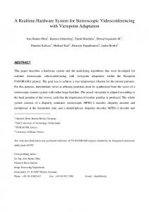
In a manufacturing system, PLC is used to control the behaviors of the system. The operating actions of the system and the sequence of these actions were edited beforehand into the control program by the manufacturer. The control program sets a series of operations of the manufacturing system, which tells the PLC how to control a system. The control loop of a PLC and the overall model of a PLC controlled manufacturing system can be described as in Figure 1 and Figure 2 respectively [4]. For (ever) { Read all PLC inputs; Evaluate the PLC program; Set all PLC outputs; }
Figure 1. The PLC control loop
Actuator states
PLC outputs
Detailed actuator behaviors
PLC program
Sensors
PLC inputs
Physical model
Control model
Figure 2. The overall model for a PLC controlled manufacturing system The PLC controls the manufacturing system according to its control program, which is embedded in the controller. When a fault occurs, the current states of all sensors or actuators are saved as an array of input, output or flag signals in the PLC memory. Therefore, the PLC program is the basis of diagnosis in a PLC controlled manufacturing system.
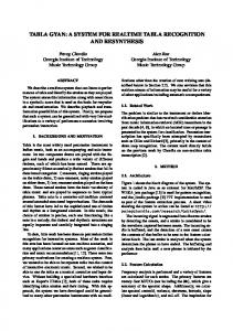
understand the behavior of the manufacturing system, we need to understand how both of its two sub-systems behave and how they interact with each other [1]. That is to say, we need to have knowledge about their linkage, the wiring diagrams, which as mentioned above, include the PLC program and the pneumatic and hydraulic circuit diagrams. PLC controlled manufacturing systems have automatic monitoring available for faults characterized by discrete state signals in their PLC memory. These discrete state signals indicate the operating states of the manufacturing systems, by which further diagnosis can be carried out. These signals can be obtained directly using a real-time linkage (RS232 series interface) between the PLC I/O board and the diagnostic system computer (This can also be carried out via several informationtechnical levels using LAN), which are the major contents of the diagnostic system database. It can be seen that, an automatic diagnosis of PLC controlled manufacturing systems is to use specific reasoning algorithms to search all the possible fault causes under the help of the relevant diagnostic knowledge as well as real-time data. Therefore, a knowledge-based system scheme is suitable for the diagnosis of complex PLC controlled manufacturing systems. The knowledge acquisition task involved in the development of such a system is extremely time-consuming, thus more disincentive. If all the diagnostic knowledge is acquired artificially from a large amount of documentation for the physical systems, they will often be inconsistent and incomplete, and therefore lead to false diagnosis or inaccurate diagnosis. Model-based knowledge acquisition mechanisms can help to solve this problem, which will result in the improvement of knowledge acquisition and diagnosis efficiency. Figure 3 is the general structure of a knowledge-based real-time diagnostic system for PLC controlled manufacturing systems. It is the extension of an existing diagnostic system we developed for a Flexible Manufacturing System (FMS) [7]. The system can continuously acquire data from the PLC, identify possible faults, search for their causes and suggest corrective actions. The knowledge associated with pneumatic and hydraulic circuit diagrams is acquired artificially by knowledgeable engineers, while the knowledge associated with the PLC program is acquired from the source code running the PLC automatically or half automatically by model-based methods. 4.
3.
DIAGNOSTIC KNOWLEDGE ACQUISITION
THE DIAGNOSTIC SYSTEM DESIGN
From Figure 2 we can know that, when diagnosing a PLC controlled manufacturing system, we always have to consider both of its two sub-systems, i.e., the control system (PLC) and the physical system (the system being controlled), which are linked by wiring diagrams. These wiring diagrams are maintained separately from the PLC program and the pneumatic and hydraulic circuit diagrams those typically constitute the documentation for the physical system. Usually in order to
4.1 Artificial knowledge acquisition In a PLC controlled manufacturing system, there are some alarms for the purpose of self-protection of the system. Each alarm is normally indicated via one PLC signal or the combination of multiple PLC signals. These alarms protect the manufacturing system from working in an error condition. An alarm appears when there is a fault such as • the temperature is too high (temperature of a motor, temperature of a bearing, temperature of the control cabinet,
Manufacturing system PLC program
Model-based knowledge acquisition
Pneumatic and hydraulic circuit diagrams
PLC I/O board
Artificial knowledge acquisition
Knowledge base
Real-time data acquisition
Database
Diagnostic reasoning
Diagnostic report 1. Possible faults
2. Fault causes
3. Corrective actions
Figure 3. The general structure of the diagnostic system
temperature of the hydraulic and cooling oil); the pressure is too low (hydraulic and pneumatic pressure); the circuit is broken (the current is too high); the oil level is not high enough (hydraulic and cooling oil); an error operation is made (protection doors, push buttons, switches); etc. Knowledge about such a fault alarm can be described as • • • •
Figure 4 is an example of an elevator in a PLC controlled production line. When there is a control command, a relevant valve will then be activated and make the elevator move the table to its top or bottom position. At the top and bottom positions of the table, there are two limit switches (LS1 and LS2) which are used to detect the current position of the table.
fault