AbstractâSynchronization and cell search are of fundamental importance for the 3rd Generation Partnership Project (3GPP). Long Term Evolution (LTE) ...
A Low Complexity Scheme for S-SCH Detection in 3GPP LTE Downlink System Feng Wang, Yu Zhu, Member, IEEE, and Zongxin Wang, Member, IEEE
Abstract—Synchronization and cell search are of fundamental importance for the 3rd Generation Partnership Project (3GPP) Long Term Evolution (LTE) downlink system. In LTE, the secondary synchronization channel (S-SCH) contains the information of 10 ms frame timing and cell identity group. Hence, it is important for user equipment (UE) to detect S-SCH effectively. In this paper, we present a low computational complexity and reliable scheme for S-SCH detection. In contrast to the optimal maximum likelihood sequence detection (MLSD) scheme, in the proposed scheme, the cross correlation method for getting the candidate sequences and the MLSD algorithm for the final decision are performed in the even and odd positions of the received S-SCH sequences respectively, where it has a significantly low computational complexity. Simulation results demonstrate that our proposed scheme has a high detection correct probability, and performs well at poor channel estimation.
contain the cell identity information. Thus, with the help of P-SCH and S-SCH, a UE can realize the synchronization and get the cell identity. Table I and Table II provide us procedures of the LTE downlink synchronization and physical-layer cell identity search respectively. TABLE I 3GPP LTE DOWNLINK SYNCHRONIZATION PROCEDURE. Step
Procedure
1
Implementation
Frequency Scanning
Select the enter of signal frequency
2
Symbol Timing
P-SCH Detection
3
Frequency Offset Correct
Channel Estimation
4
CP Length Detection
Prepare for the S-SCH Detection
5
10 ms Frame Timing
S-SCH Detection TABLE II
Index Terms— 3GPP LTE, Synchronization, S-SCH, MLSD.
PROCEDURE OF PHYSICAL CELL IDENTITIES
F
I. INTRODUCTION
uture wireless systems should provide broadband wireless services to multiple users while guaranteeing different and stringent quality of service (QoS) requirements despite the variations in the channel quality, network traffic, and user mobility. The 3rd Generation Partnership Project Long Term Evolution (3GPP-LTE) system [1] has been proposed as one of the important standards to meet these challenges. 3GPP LTE adopts the technique of orthogonal frequency multiple access (OFDMA) which combines orthogonal frequency division multiplexing (OFDM) and frequency division multiple access (FDMA). LTE thus has the advantages as follows: high spectrum utilization, flexible system scalability and good resistance to multipath fading. In LTE, in order to keep the orthogonality among subcarriers, synchronization is important for downlink systems. And user equipment (UE) can get the cell identity with respect to time and frequency synchronization. LTE provides two synchronization channels, i.e., the primary synchronization channel (P-SCH) and the secondary synchronization (S-SCH), to help UE to get synchronized with the base stations (BS) and to activate a cell search procedure. P-SCH helps UE to acquire the symbol timing and carrier frequency offset, and S-SCH can help UE to acquire the frame timing. Both P-SCH and S-SCH This work was supported in part by the National Natural Science Foundation of China under Grant No.60802010, and the Important National Science and Technology Specific Projects under Grant 2009ZX03002-003. F. Wang, Y. Zhu, and Z. Wang are with the Department of Communication Science and Engineering, Fudan University, Shanghai, China
978-1-4244-9003-5/10/$26.00 ©2010 IEEE
Step
Procedure
Implementation
Search for Sector Cell Index: N
1
( 2) ID
P-SCH Detection (1)
Search for Cell Identity Group: N ID
2
cell N ID DETECTION.
S-SCH Detection
According to the 3GPP-LTE standard [1], there are 504 unique cell physical-layer cell identities, denoted by N ID . The () ( ) cell physical-layer cell identities are defined as N ID = 3 N ID + N ID , 1
where
() N ID 1
denotes
the
cell
identity
group
2
with
( 2)
(1)
N ID ∈ {0,1,… ,167} , and N ID denotes the sector cell index ( ) ∈ {0,1, 2} . For LTE, P-SCH within the group with N ID 2
( ) contains the information of N ID and S-SCH contains that 2
() . By correctly detecting both P-SCH and S-SCH, a UE of N ID 1
cell cell , where N ID = 0,1,… ,504 . can successfully identify the N ID In this paper, we present a low complexity scheme for S-SCH detection, compared to the well-known optimal maximum likelihood sequence detection (MLSD) scheme. For optimal MLSD scheme, the likelihood metrics of all the S-SCH data sequences should be calculated. In our proposed scheme, we divide the whole detection procedure into two steps, where in the first step we obtain several candidate S-SCH sequences by the cross correlation in even positions of the sequences, and in the second step we apply MLSD algorithm to the candidate S-SCH sequences in odd positions.
The rest of this paper is organized as follows. Section II gives the system model and briefly introduces the well-known optimal MLSD scheme. Section III presents the proposed scheme design and compares the computational complexity of the proposed scheme with that of the conventional MLSD scheme. Section IV gives some simulation results, followed by our conclusion in Section V. II. SYSTEM MODEL
generated from an original binary m-sequence s ( n ) with cyclical offsets m0 and m1 respectively, that is,
⎧ sm ( n ) = s ( ( n + m0 ) mod 31) , ⎪ 0 ⎨ ⎪⎩ sm1 ( n ) = s ( ( n + m1 ) mod 31) ,
(⋅) mod N
(2)
is the modulo-N operation. zm0 ( n ) and
zm1 ( n ) denote two sequences generated from an original
m-sequence
z (n)
D (0)
D ( 30 )
D (1)
X −31
X −30
with cyclical offsets m0 mod 8 and
( (
) )
() N ID . Sequences c0 ( n ) and c1 ( n ) are derived from cyclically 1
shifted an original m-sequence c ( n ) , that is,
((
) )
) )
( 2) ⎧c ( n ) = c n + N ID mod 31 , ⎪ 0 ⎨ ( 2) ⎪c1 ( n ) = c n + N ID + 3 mod 31 , ⎩
((
2
X1
X0
X 30
X 31
H k to data sequences D ( n ) for S-SCH.
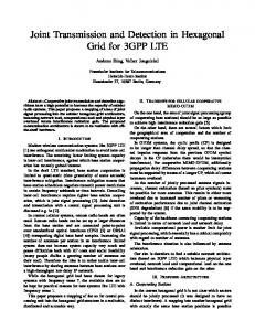
Assuming that in a LTE system, before the S-SCH detection, a UE has completed OFDMA symbol synchronization and frequency synchronization. Then the received signal on the k -th subcarrier of that UE can be represented by Yk = X k H k + Wk , (5) for k = −31, −30,… , 0,1,… ,31. where X k is the data symbol transmitted and H k is the channel frequency response on that subcarriers, Wk is additive white Gaussian noise (AWGN). The S-SCH detection is performed by first de-mapping the subcarriers in order to obtain the received data sequence on the corresponding subcarriers assigned to S-SCH. Denote the received S-SCH sequence by Y ( n) = H (n) D ( n) + W ( n) , (6) for n = 0,1,… , 61, where the relationship of the sequence index n with the subcarrier index k is the same as that in Fig. 1. Since at this stage, the UE only obtains 5 ms timing information and the S-SCH sequences in subframe 0 and subframe 5 are different, an easy way is to save the two consecutive received S-SCH sequences in one 10 ms frame so that the S-SCH detection can be performed based on these two different sequences. Denoting the two received S-SCH sequences by Y1 and Y2 respectively, there are Y1 = {Y1 ( 0 ) , Y1 (1) ,… , Y1 ( 61)} ;
Y2 = {Y2 ( 0 ) , Y2 (1) ,… , Y2 ( 61)} .
Finally, we investigate the use of the optimal maximum-likelihood sequence detection (MLSD) algorithm for detecting S-SCH in 3GPP-LTE system downlink. () mapping to one According to [1], each cell identity group N ID 1
indices pair ( m0 , m1 ) , thus corresponds to two S-SCH data sequences, and without considering the order of sequences. So
(5)
( ) ( ) where the offsets are N ID and N ID + 3 respectively. In LTE, S-SCH is located at the center 1.25 MHz frequency band, corresponding to 72 subcarriers, for all transmission bandwidth. Among them, only 62 subcarriers carry the synchronization signals and 5 null subcarriers at both ends are reserved. The mapping of the data sequence in (1) on the 62 2
• • •
X −1
m1 mod8 respectively, that is,
⎧ z ( n ) = z ( n + ( m mod 8 ) ) mod 31 , 0 ⎪ m0 (4) ⎨ ⎪ zm1 ( n ) = z ( n + ( m1 mod 8) ) mod 31 , ⎩ where the indices m0 and m1 are uniquely determined by
D ( 60 ) D ( 61)
D ( 31)
• • •
Fig. 1. The mapping of subcarriers
In this section, we first introduce the data sequence of S-SCH defined in 3GPP-LTE standard [1] and the mapping of S-SCH data sequence to the well-known optimal MLSD scheme for the detection of S-SCH. In the 3GPP-LTE system downlink as defined in [1], the frame duration is 10 ms and each frame consists of 10 subframes and each subframe duration is 1 ms. The S-SCH signal is transmitted every 5 ms, i.e., in subframe 0 and subframe 5. The S-SCH data sequence is generated as follows: ⎧⎪ sm0 ( n ) c0 ( n ) , subframe 0 D ( 2n ) = ⎨ subframe 5 ⎪⎩ sm1 ( n ) c0 ( n ) , , (1) ⎧⎪ sm0 ( n ) c0 ( n ) zm0 ( n ) , subframe 0 D ( 2n + 1) = ⎨ ⎪⎩ sm1 ( n ) c0 ( n ) zm1 ( n ) , sbuframe 5 where n = 0,1,… ,30 . sm0 ( n ) and sm1 ( n ) are two sequences
where
subcarriers is shown in Fig. 1.
{
}
m m there is ⎡ D1( ) , D2( ) ⎤ , m = 1, 2,… ,336 , and it corresponds to ⎣ ⎦
() N ID = 0,1,… ,167 , where 1
{ ) ( 0) , D( ) (1) ,…, D( ) ( 61)} ; D ( ) = { D ( ) ( 0 ) , D ( ) (1) ,… , D ( ) ( 61)} .
D1(
m)
= D1(
m
2
m
m
1
m
2
m
1
m
2
m
2
For two consecutive S-SCH data sequences Y1 and Y2 , we note the Euclidian distance metric Ω ( m ) , as follows, Ω (m)
( ) = ∑ (Y ( n ) − Yˆ ( ) ( n ) ) m m D Y1 , Y2 ; Yˆ1( ) , Yˆ2( ) 61
m
1
2
1
n=0
61
(
)
2
m + ∑ Y2 ( n ) − Yˆ2( ) ( n ) , n =0
(7)
m m m m Where Yˆ1( ) and Yˆ2( ) are estimations of D1( ) and D2( ) respectively, as follows, ⎧⎪Yˆ1( m ) ( n ) = D1( m) ( n ) Hˆ 1 ( n ) , n = 0,1,… , 61, (8) ⎨ ( m) ( m) ⎪⎩Yˆ2 ( n ) = D2 ( n ) Hˆ 2 ( n ) , n = 0,1,… , 61, where m m m m Yˆ ( ) = Yˆ ( ) ( 0 ) , Yˆ ( ) (1) ,… , Yˆ ( ) ( 61) ;
{ } Yˆ ( ) = {Yˆ ( ) ( 0 ) , Yˆ ( ) (1) ,… , Yˆ ( ) ( 61)} ; Hˆ = { Hˆ ( 0 ) , Hˆ (1) ,… , Hˆ ( 61)} ; Hˆ = { Hˆ ( 0 ) , Hˆ (1) ,… , Hˆ ( 61)} . 1
1
m
1
m
2
2
1
m
m
2
1
1
2
2
2
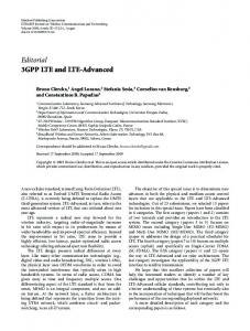
Fig. 2. The workflows of the proposed scheme.
indices m0 and m1 of one S-SCH signal are uniquely determined by the cell identity group N ID( ) , and at the same time 1
m0 , m1 ∈ {0,… ,30} for each N ID( ) . Once m0 and m1 are 1
detected, then N ID( ) can be identified. Therefore, the proposed 1
( m0 , m1 )
1
to N ID( ) . 1
Fig. 2 shows the workflows of the proposed scheme. The first step is to attain the candidate pairs ( m0 , m1 ) based on the
2
The optimal MLSD algorithm determines the sequence that minimizes the Euclidian distance metric (7), that is, m∗ = arg min {Ω ( m )} .
1
scheme first aims for obtaining m0 and m1 , and then maps
2
1
() N ID
(9)
m
( m∗ ) ( m∗ ) Thus, once we get the optimal sequence ⎡⎢ D1 , D2 ⎤⎥ , we ⎣ ⎦ () can obtain the corresponding N ID and complete the S-SCH detection.
even positions of the received S-SCH signal, and the second step is to determine one pair ( m0 , m1 ) from the previous candidate pairs with MLSD algorithm which based on the odd positions of the received S-SCH signal. In the following, we will illustrate each step of the proposed detection scheme in details respectively.
1
III. PROPOSED LOW COMPLEXITY DETECTION SCHEME In this section, we first present the proposed detection scheme for S-SCH. We also analyze the computational complexity of the proposed scheme, and compare it with that of the optimal algorithm. The proposed scheme consists of two steps. The first step is to attain candidate transmitted S-SCH sequences based on the received S-SCH data sequences in even positions. The second step is to determine the transmitted S-SCH sequences based on the received S-SCH sequences in odd positions with the application of MLSD algorithm. The two-step detection procedure is depicted in Fig. 2. A. The Proposed Detection Algorithm In this part, we mainly present the proposed scheme for S-SCH detection. As mentioned in Section II, the proposed scheme is also based on two successive S-SCH data sequences every 10 ms in 3GPP-LTE downlink. By observing (1), for one S-SCH signal, it consists subframe 0 and subframe 5, and the even positions of subframe 0 and that of subframe 5 include the complete information m0 and m1 respectively, while the odd positions of both subframe 0 and subframe 5 include the information m0 and m1 . Note that, the
Step 1: Attain the candidate indices pairs from the even positions of the received subframes, by the correlation operator. In this step, the received S-SCH signal consists two subframes either in the order of subframe 0 and subframe 5, or in the order of subframe 5 and subframe 0. As described in the system model (6), two successive S-SCH subframes are noted as Y and Y respectively. And the channel estimations Hˆ 1
2
1
and Hˆ 2 derived from P-SCH are then applied to equalize the S-SCH subframes in even positions. The frequency domain equalization takes the form of
⎧⎪ Dˆ1 ( 2n ) = Y1 ( 2n ) / Hˆ 1 ( 2n ) , n = 0,1,...,30, (10) ⎨ ⎪⎩ Dˆ 2 ( 2n ) = Y2 ( 2n ) / Hˆ 2 ( 2n ) , n = 0,1,...,30, where the sequences Dˆ1 ( 2n ) and Dˆ 2 ( 2n ) are the estimations of two received S-SCH subframes in even positions respectively. Descrambling Dˆ1 ( 2n ) and Dˆ 2 ( 2n ) by the binary sequence c0 ( n ) (see (4)) in the even positions, we can get the descrambled sequences r1 ( n ) and r2 ( n ) respectively, as follows, ⎧⎪ r1 ( n ) = Dˆ1 ( 2n ) c0 ( n ) , ⎨ ⎪⎩ r2 ( n ) = Dˆ 2 ( 2n ) c0 ( n ) ,
n = 0,1,...,30, n = 0,1,...,30,
(11)
{
U = ( u1 ( j ) , u2 ( j ) )
TABLE III STEP 1: ATTAIN THE CANDIDATE λ INDICES PAIRS SET U. Sub-step 1.1
Procedure
{
}
Dˆτ ( 2n ) = ℜ Yτ ( 2n ) Hˆ τ ( 2n ) n=0, 1,…, 30, τ =1,2.
1.2
Descrambling
1.3
Cross Correlation
Step2: Determine one indices pair from the candidate pairs by MLSD algorithm based on the odd positions of the received subframes. In this step, we first generate S-SCH subframe 0 and subframe 5 in odd even positions as the candidate S-SCH
rτ ( n ) = Dτ ( 2n ) c0 ( n )
n=0, 1,…,30, τ =1,2. 30
Γτ ( d ) = ∑ rτ ( n ) sd ( n )
subframes for each indices pair ( u1 ( j ) ,u2 ( j ) ) ontained in the
n=0
n=0, 1,…,30, τ =1,2. 1.4
Sort in the Decreasing Order
1.5
Select the First L Offsets
Γτ ( dτ ( 0 ) ) ≥ … ≥ Γτ ( dτ ( 30 ) )
previous step, where j = 0,..., λ − 1 . Then we apply the MLSD algorithm to the received two subframes among the candidate (1) subframes, we can get the indices pair, and maps it to N ID .
n=0, 1,…,30, τ =1,2.
dτ ( 0 ) ,… , dτ ( L − 1) τ =1, 2.
First, we generate the sequences su1 (j )(n) and su2 (j )(n) with
{( d ( p ) , d ( q ))} , B = {( d ( p ) , d ( q ) )} , A=
1.6
Match Offsets in Pairs
1.7
Get the Candidate λ Pairs in the Set U
1
2
2
1
p q = 0, …, L – 1.
{
}
U = ( u1 ( j ) , u2 ( j ) ) ,
j = 0, …,λ - 1.
( ) which has been known at the where c0 ( n ) relies on N ID 2
P-SCH detection in Table Ι . Next, we will find the candidate offsets of sequences r1 ( n ) and r2 ( n ) respectively. Based on m-sequence properties,
we correlate r1 ( n ) and r2 ( n ) with sd ( n ) respectively, where sd ( n ) = s ( ( n + d ) mod 31) . We
also
note
down
the
correlation
Γ 2 ( d ) respectively, as follows, 30 ⎧ Γ = n r1 ( n ) sd ( n ), ( ) ∑ 1 ⎪ ⎪ n=0 ⎨ 30 ⎪Γ ( n ) = r ( n ) s ( n ), ∑ d 2 2 ⎪⎩ n=0
Γ1 ( d ) and
d = 0,1,...,30,
offsets are d1 (
d = 0,1,...,30,
) and
d2 (
)
) respectively,
and and
= 0,..., L − 1 . Then we match the offsets d1 (
{ {
⎧ A = ( d ( p ) , d ( q )) 1 2 ⎪ ⎨ ⎪ B = ( d 2 ( p ) , d1 ( q ) ) ⎩ where we search the elements of “Mapping between physical-layer
m-sequences corresponding to z(n) with offsets u1(j) and u2(j) respectively, see (4). Then, the channel estimation Hˆ 1 and Hˆ 2 in odd positions are applied to compensate the sequences T1, j and T2, j or T2, j J1, j and J 2, j respectively, where
(12)
respectively, and note down the first L values Γ1 (
) whose
the known offset u1(j) and u2(j), respectively. And then according to (1), we generate the S-SCH subframes 0 and subframes 5 in the odd positions and note them as Τ1, j and Τ2, j respectively, where Τ1, j = {Τ1, j(0), Τ1, j(0),…, Τ1, j(30) }; Τ2, j = { Τ2, j(0), Τ2, j(1)…, Τ2, j(30) }. and we have ⎪⎧T1, j (n) = su2 (j )(n) c1 (n) zu1 (j )(n), n = 0,1,...,30, (15) ⎨ ⎪⎩T2, j (n) = su1 (j )(n) c1 (n) zu2 (j )(n), n = 0,1,...,30, where j = 0,…,λ-1, both sequences z(n) and zu2 ( j ) ( n ) are binary
and T1, j respectively, thus we can obtain such sequences as
where we sort Γ1 ( d ) and Γ 2 ( d ) in decreasing order Γ2 (
(14)
In a brief summary, Table Ⅲ presents the implementation in the step 1.
Implementation
Equalization
j = 0,..., λ − 1} .
) and
d2 (
) in the form of
p, q = 0,..., L − 1}, p, q = 0,..., L − 1},
(13)
A and B which exist in the (1) and cell identity group N ID
the indices ( m0,m1 ) ”, as shown in table 6.11.2.1-1 in [1], and we note down such elements as
( u ( j ) ,u ( j ) ) 1
2
, where
j = 0,..., λ − 1 . Now, we have obtained the candidate λ indices pairs in the set U , as follows,
{ = {J
} (30)} .
J1, j = J1, j (0),..., J1, j (30) ; J 2, j
2, j
(0),..., J 2, j
These are two cases in the procession. The first case is that the received S-SCH subframes are in the order of subframe 0 and subframe 5, i.e., (u1 (j ),u2 (j )) ∈ A , then ⎧⎪ J1, j (n) = Hˆ 1 (2n+1)T1, j (n), (16) ⎨ ⎪⎩ J 2, j (n) = Hˆ 2 (2n+1)T2, j (n), and the second case is that the received subframes in the order of subframe 5 and subframe 0, i.e., (u1 (j ),u2 (j )) ∈ B , then ⎧⎪ J1, j (n) = Hˆ 1 (2n+1)T2, j (n), (17) ⎨ ⎪⎩ J 2, j (n) = Hˆ 2 (2n+1)T1, j (n), where j = 0,..., λ − 1, n = 0,1,...,30. Now, we implement the MLSD algorithm for received subframes Y1 and Y2 in the odd positions, the Euclidian distance metric is given by
(
Λj
D Y1 , Y2 ; J1, j , J 2, j 30
{(
) ) (
= ∑ Y1 ( 2n + 1) − J1, j ( n ) + Y2 ( 2n + 1) − J 2, j ( n ) n=0
2
) } (18) 2
j = 0,..., λ − 1.
for
where Λ j denotes the Euclidian distance metric between ⎡⎣ J1, j J 2, j ⎤⎦ and [Y1 Y2 ] in odd positions. The MLSD algorithm searches for the minimum Euclidian distance Λ j , where j = 0,..., λ − 1 , and we get
j ∗ = arg
{
min Λ j
j = 0,..., λ −1
}
(19)
where j ∗ denotes the decision on j and we can obtain
(u ( j ) ,u ( j )) . ∗
1
∗
2
In a brief summary, Table IV presents the workflows in this step. TABLE IV * * STEP 2: DECIDE ONE INDICES PAIR (u1(j ), u2(j )) IN THE SET U. Sub-step
2.1
2.2
Procedure Get the Sequences * with Offsets u1(j )
and u2(j*)
Get S-SCH subframes in the Odd positions T1, j and
T2, j
2.3
Implementation
su1 ( j ) ( n ) , su2 ( j ) ( n ) z u1 ( j ) ( n ) , zu2 ( j ) ( n ) n=0, 1,…,30, j =0,…,λ-1.
T1, j ( n ) = su2 ( j ) ( n ) c1 ( n ) zu1 ( j ) ( n ) T2, j ( n ) = su1 ( j ) ( n ) c1 ( n ) zu2 ( j ) ( n )
n=0, 1,…,30, j =0,…,λ-1. When (u1(j), u2(j)) in the
Signal Compensate Get J1, j and J2, j
set B
⎧⎪J1, j ( n) = Hˆ 1 ( 2n +1) T2, j ( n) ⎨ ⎪⎩J2, j ( n) = Hˆ 2 ( 2n +1) T1, j ( n) n=0, 1,…,30, j =0,…,λ-1.
Λ j = D (Y1 , Y2 ; J1 , J 2 ) 30
2.4
Get Euclidian Distance Λ j
(
)
2
(
)
2
= ∑ Y1 ( 2n + 1) − J1, j ( n ) n =0
30
+ ∑ Y2 ( 2n + 1) − J 2, j ( n ) n =0
j =0,…,λ-1. 2.5
Apply MLSD
2.6
Get the Indices Pairs From the Set U
⎧ ⎫ j ∗ = arg ⎨ min Λ j ⎬ j 0, … , λ 1 = − ⎩ ⎭
{ }
(u ( j ) , u ( j )) 1
∗
2
( ( ) ( ) ) to N
Finally, we map u1 j ∗ ,u2 j ∗
(1)* ID
the set U, where (u1 (j * ),u2 (j * )) ∈ U , j = 0,...λ − 1 . Note that the MLSD algorithm in the proposed scheme searches the minimal Euclidian distance among Λ j in the odd position of the received S-SCH subframes Y1 and Y2, i.e., min{Λj}, where j = 0,…,λ -1. So the computational complexity is proportional to the number of the candidate indices pair, i.e., λ and the length of the subframes in odd positions, i.e., 62. Hence, the total computational complexity mainly relies on the 31× 2 + λ × 31× 2 complex multiplications in the proposed scheme, while the optimal MLSD scheme uses about 168 × 2 × 62 × 2 = 41664 complex multiplications which much more than that of our proposed scheme. Table V provides the computational complexity of both the proposed scheme and the optimal MLSD scheme.
set A
⎧⎪ J1, j ( n ) = Hˆ 1 ( 2n + 1) T1, j ( n ) ⎨ ⎪⎩ J 2, j ( n ) = Hˆ 2 ( 2n + 1) T2, j ( n ) n=0, 1,…,30, j =0,…,λ-1. When (u1(j), u2(j)) in the
algorithm. It is shown that our proposed algorithm has a lower computational complexity for S-SCH detection in 3GPP-LTE downlink. In the proposed scheme, the first step mainly involves the frequency domain equalization and cross correlation. In Tab. III step 1.1, the equalization for Y1(2n) and Y2(2n) needs about 62 complex multiplications assuming that the channel estimation bank provides the unit 1/Hk , In Table III sub-step 1.3, the cross correlation between Y1(2n) and sd(n), and that of between Y2(2n) and sd(n) involve none of complex multiplication, because sd(n) is the binary m-sequence which consists of +1 and -1. In the second step, we apply MLSD algorithm to determine one indices pair (u1 (j * ),u2 (j * )) which denotes the decision on
∗
. So far, we have
completed the proposed detection scheme. B. Computational Complexity Analysis In this part, we analyze the computational complexity of the proposed scheme, and compare it with that of optimal MLSD
TABLE V THE COMPUTATIONAL COMPLEXITY COMPARISON. The optimal MLSD Scheme The Proposed Scheme Scheme Number of All λ 168×2 Sequences Length of Each 31×2 62×2 Sequences Number of Complex 41664 λ×62+62 Multiplications
IV. SIMULATION RESULTS In this section, we first present some simulation results to compare the proposed detection scheme with the optimal MLSD scheme. We also evaluate the effect of channel estimation variance on the performance of the proposed scheme. In the simulation, the channel is assumed to be a 8-ray exponentially delay power profile Rayleigh fading channel with the power on each ray being 2 exp(−α ) (20) E⎡ h ⎤ = 7 , ⎦⎥ ⎣⎢ ∑ exp(−α ) =0
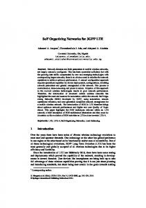
where ℓ = 0,1,…,7 and α = 1. Fig. 3 shows the detection correct rate of cell identity group
V. CONCLUSION 1
Detection correct rate
0.95 0.9 0.85 0.8 L= 5 (proposed) L=10 (proposed) L=15 (proposed) The optimal MLSD scheme
0.75 0.7
-5
0
5
10
Eb/N0 (dB)
15
20
In this paper we proposed a novel low complexity and (1) in reliable detection scheme for cell identity group N ID 3GPP-LTE system downlink. In the proposed scheme, the cross correlation method is adopted for getting the candidate indices pairs and the MLSD algorithm is applied for the final decision in the even and odd positions of the received S-SCH sequences respectively. It has been shown that the proposed scheme has a much lower computational complexity compared to the optimal MLSD scheme, i.e., only 4.6% of the optimal MLSD scheme. Simulation results have illustrated that our proposed algorithm has a fairly reliable detection performance and it is robust to channel estimation error.
(1) Fig. 3. Detection performance for cell identities group N ID , when channel
estimation error variance σ2 = 0.01. (1) N ID as a function of Eb/N0, where L denotes that in the first step of our proposed scheme, we select L offsets in Table III sub-step1.5 and the channel estimation error variance σ2 =0.09. In Fig. 3, we investigate the performance of our proposed scheme at the cases L = 5, L = 5 and L = 5 respectively. For comparison, we also present the optimal detection performance that has been described in (7) - (9). We can see that the proposed scheme performance relies on L. As the increase of L, the performance becomes closer to that of the optimal scheme. Moreover, in the interested Eb/N0 shows the detection correct (1) rate of cell identity group N ID as a function of Eb/N0 region, the proposed scheme only has a little performance loss compared with the optimal scheme, and the detection correct rate can remain above 0.95 with channel estimation error variance σ2 =0.01. Fig. 4 illustrates the performance of the proposed scheme at different channel estimation error variance σ2, when Eb/N0 = 0 dB and L = 8. It is shown in this figure that, in this low Eb/N0
Detection correct rate
REFERENCES [1]
[2] [3] [4] [5] [6] [7]
0.95 0.94
[8]
0.93
[9]
0.92 0.91 0.9 0.89 0.01
ACKNOWLEDGMENT This work is supported in part by the National Natural Science Foundation of China under Grant No.60802010, and the Important National Science and Technology Specific Projects under Grant 2009ZX03002-003.
0.03
0.05
2
Channel estimation error variance σ ,
0.07
0.09
when Eb/N0= 0 dB
Fig. 4. The proposed scheme performance when Eb/N0 = 0 dB.
point, the proposed scheme can still achieve around 0.88 detection correct rate, even with channel estimation error variance σ2 =0.09.
3rd Generation Partnership Project, Technical Specification Group Radio Access Network, Evolved Universal Terrestrial Radio Access, Physical Channels and Modulation (Release 8), 3GPP TS 36.211 V 8.5.0 (2008-12). H. Sari, G Karam, and I. Jeanclaude, “Transmission techniques for digital terrestrial TV broadcasting,” IEEE Commun. Mag., vol.33, no. 2, pp.100-109, Feb. 1995. A. Verterbi, “Optimal detection and signal selection for partially coherent binary communication,” IEEE Trans. Inform. Theory, vol. 11, pp. 239-246, Apr. 1965. J. J. Komo and W. J. Reid III, “Generation of canonical m-sequence and dual bases,” IEEE Trans. Inform. Theory, vol. 42, pp. 638-641, Mar. 1997. J. G. Proakis, Digital Communications, 4th ed. McGraw-Hill, 2001, ch. 5. R. O. Harger, “Signal sequence detection given noisy, common background image sets,” IEEE Trans. Aerosp. Electron. Syst., vol. AES-8, no. 2, pp.174-185, Mar. 1972. F. Gini and G. B. Giannakis, “Frequency offset and symbol timing recovery in flat-fading channels: a cyclostationary approach,” IEEE Trans. Comm., vol. 46, no. 3, pp. 400-411, May. 1998. H. V. Trees, Detection, Estimation, and Modulation Theory: Part I, 1st ed. Wiley, 2001, ch. 2. T. S. Rappaport, Wireless Communications: Principles and Practice, 2nd ed. Prentice Hall, 2001, ch. 7.