object declarations are shown in Code 1. architecture CORRECT of ASIC1 is signal Dat1: std_logic; signal Data2: bit; signal Ctrl1: std_logic_vector(3 downto 0);.
A method to perform error simulation in VHDL∗ C. López, T. Riesgo, Y. Torroja, E. de la Torre, J. Uceda Universidad Politécnica de Madrid División de Ingeniería Electrónica. E.T.S. Ingenieros Industriales C/ José Gutiérrez Abascal, 2. E-28006 Madrid (Spain) Tel. +34-91-336 31 91. Fax. +34-91-564 59 66 e-mail: {celia, teresa, yago, eduardo, uceda}@upmdie.upm.es Abstract: This paper describes a method to perform error simulation to estimate the quality of the testbenches used to validate VHDL designs. The method is based in the mutation of VHDL descriptions by an error model. The proposed method allows an automatic execution of the error simulation using a commercial VHDL simulator. The resulting tool will be integrated in an environment devoted to quality checking of VHDL designs. 1. Introduction ASIC design methodologies are currently based in top-down approaches where the design vehicle is a hardware description language [1]. The design is made in sequential phases, beginning from the specification, through the architectural design, the detailed design and the physical design. The step from one phase to the next one is performed by means of refinement processes, such as synthesis. During the whole design cycle, the designer has to check that the functionality is correct by simulating the HDL descriptions generated in all the steps. One problem that appears is to know if the test-bench used is good enough to check the circuit functionality. This question is especially difficult to answer if we take into account that an exhaustive check is not possible and the circuit environment has to be considered to generate “high quality” testbenches. However, we could have a measure that indicates the need of completing the simulation stimuli to activate more deeply the circuit functionality. This is difficult to observe from a structural description, where no behaviour is represented, and it is easier to get from behavioural descriptions. Moreover, within top-down methods, the test-benches generated at the architectural design phase are reused at lower abstraction levels, so the quality of these test-benches have to be good enough to assure the quality of the final design. All the techniques presented in this paper are developed for synthesisable descriptions written in VHDL [2]. The proposed tool will estimate the quality of a set of functional stimuli to validate a design or just part of it. It will be integrated in a larger environment dedicated to quality checking of VHDL designs, stressing reusability and reliability issues [3]. ∗
The method is based on the detection of modelled errors. This approach has been proposed by several authors using different types of descriptions, such as [4] where structural descriptions at the logic level were used. In [6], for example, error models for structural descriptions are also proposed with a method for design validation quality measurement. In one of our previous works [5], we presented the method and evaluated it with a set of examples, demonstrating the accuracy of the measurement used based on the error model. The paper is structured as follows. In the following section, the error model used as the base for the method is presented. Section 3 explains in detail the steps to be taken to perform the error simulation, as well as different considerations about the implementation. Section 4 shows some experimental results. At the end some conclusions are extracted. 2. The error model The error model used in the error simulation tools is based on three different classes: Stuck, which affects data or expressions. It assumes that a data or expression under error takes a permanent value. Switch, which affects data or expressions. It assumes that a reference to the data or expression under error is replaced by another one. Dead, which affects statements of the code, making that a statement under error is never executed. This error model is defined for synthesisable descriptions in VHDL. The main features of the error model are the accuracy and the simplicity. It is accurate as the detection of the modelled errors implies that the description is correctly tested and a low level of detection refers to some lacks in the simulation vector set. The simplicity is achieved by the selection of the modelled errors. This way only those errors that are more likely to occur are modelled, with features as the consideration of singular values and restricted scopes.
This work has been partially funded by TOMI project (ESPRIT #20724)
Table 1 shows a summary of the error model. For more details see [5], where the evaluation of the error model is presented.
enum. expressions integer statement
dead
arrays
stuck
switch
data
error
description These errors affect the left-hand part of the assignment statements, making the target data of the assignment being changed to another one. Both data must have the same type and must be used in the same process or subprogram. These errors affect both the right hand part of the assignment statements and the expressions that appear in the control statements (if, case, etc.). The error can affect both the data element of the expression and the operators. The affected data or expression can be stuck at all the possible values. For bit or std_logic data types, only ‘0’ and ‘1’ will be considered The affected data or expression can be stuck-at a set of possible values, not all of them. Then, the data can be stuck-at a set of singular values extracted from the data type and the VHDL description (type bounds, referenced values, etc.) As in the previous case, the affected data or expression can be stuck-at a set of singular values: “00..0”, “11..1”, values referenced in the code, etc. The effect of these errors is that the affected statements do not execute. They can affect a single statement or a set of statements inside a control part
Table 1 Summary of the proposed error model
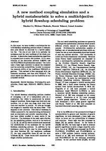
3. The method for error simulation In this section the method for checking the quality of the test-benches that are used for functional validation of these VHDL designs will be described. The method consists of the insertion of errors on the VHDL code, to prove that the test-bench is able to detect them. If most of the errors have been detected, the test bench is good; but if some errors could not be detected, the designer has to improve the test bench so that more errors are detected and the quality of the validation is enhanced. Therefore, a simple, easy and quick method is needed, without losing accuracy. Thinking of it as a black box, it receives a circuit description and its test-bench (both in VHDL), and gives back a report about the quality of the test-bench. This quality will be measured with the number of detected errors by the test-bench above all modelled errors, which will be called Error Coverage. It will be also interesting to know which errors have not been detected, so the user can generate new stimuli to verify these areas of the VHDL code that have not been tested enough. The steps for the proposed error simulation are shown in Figure 1. The procedure is divided into different steps: Error list generation, Error insertion, System configuration and Simulation. The implementation of the modules, composing the whole method for error simulation has different possibilities. The best solution was chosen after some experimentation, being the parameters to determine
the optimum solution measures like CPU time, Used Memory, User time, etc. In other cases, the easiness in the development of some solution was determinant for choosing one among all. Error Errormodel model RT/VHDL RT/VHDL
VHDL VHDLcode code
Error list generator
Error insertion
Error simulation file generator
VHDL simulator (commercial)
Error Errorlist list
VHDL VHDLmodified modified code code(E1) (E1)
VHDL VHDLerror error simulator simulatorfile file
Error Errorcoverage coverage List Listof of non-detected non-detected errors errors
Figure 1. Error simulator implementation
The block under test can be located anywhere within the hierarchy, as in the example shown in Figure 2. The tool should be capable to handle the hierarchy and to generate all extra VHDL code for simulating the whole error testing system. In the next paragraphs this block will be mentioned, meaning a whole design or a single block within the hierarchy.
K\ LHUDUF + Q J L 'HV Block to be tested
7HVW %HQFK
DUFK\
+LHU 'HVLJQ
Modified blocks Observation block
7HVW %HQFK
Figure 2. Example of Error Simulation System Generation
3.1 Error list generation This module is in charge of analysing the block/s under study and generating, according to the error model, all the errors to be inserted in the VHDL code. The input is the VHDL code of the block/s under analysis. The output will be an Error List that contains all the errors to be inserted in the VHDL code. The format of this list should be simple and easy to be understood by the next steps. Besides, the user may read the error list, so that he/she could select some errors to be discarded or not. A standard data format for the input VHDL code is needed. Using VHDL source files would imply long access time, complex data structures and slow algorithms for searching the VHDL elements. A standard data format eases the programming task and, mainly, enlightens error generation routines because VHDL elements are accessible in a unique and fast way. VHDL Intermediate Format (VIF) from LEDA VHDL System has been selected as supporting tool. The main advantage of this format is that it is delivered with a Procedural Interface that enables an easy access to the database.
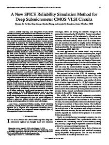
The first step in this module is to obtain the VIF format for the VHDL code. The following step is to analyse the location of those VHDL elements susceptible of being affected by an error. This task is done for each error type (stuck, switch and dead) and for each element (data, expressions and statements). Then, a mechanism for inserting the error is established, so that the output list specifies the element to be changed and the one to substitute it. 3.2 Error insertion module This module is in charge of generating mutated VHDL codes from the source VHDL code of the block. The inputs to this module are the error list generated by the previous module and the original VHDL code. The error list will contain the VHDL elements to be changed and the substitutes for them. The output will be a set of mutated VHDL codes, similar to the original one, but with only one mutated element per description. There will be as many new descriptions as elements in the error list. The way these new codes are integrated within the whole VHDL design code depends on the method chosen for configuring the error simulation system, that is described later. The error insertion method is very simple: some elements are changed by others. Two possibilities have been considered for organising the error-free VHDL code and the mutated ones: concurrent architectures and matrix scheme. In the error simulation system, additional elements have to be inserted to compare the results of the correct block and the mutated ones. Both possibilities are shown in Figure 3. Concurrent architectures Stimuli
7HVW %HQFK
Matrix scheme Stimuli
7HVW %HQFK
Comparison
Results
Changed architecture: matrix scheme
&RPSDULVRQ
&RUUHFW DUFKLWHFWXUH
Results
Erroneous results
Results
(UURQHRXV DUFKLWHFWXUHV
Figure 3. Proposed methods for error simulation
With respect to the organisation of these blocks the first solution is Concurrent architectures. This scheme generates as many architectures for the block as the number of errors (each error will be inserted in one replicated architecture). The architectures are configured within the test bench, all of them are declared as components in the test bench, and are simulated concurrently. The output signals of all of them are compared with the correct behaviour using an external module. With this method, all the VHDL code of the considered block is replicated. The Matrix scheme method consists on modifying the VHDL code of the block. The types of all the internal elements are changed to an extended array type, with as many elements as the number of errors to insert, and with the same type for the elements as
the original one. In these redefined objects, the first bit represents the correct behaviour and the rest of bits represent mutated behaviours. The changes in the object declarations are shown in Code 1. architecture CORRECT of ASIC1 is signal Dat1: std_logic; signal Data2: bit; signal Ctrl1: std_logic_vector(3 downto 0); begin ... end CORRECT; architecture ALL_ERRORS of ASIC1 is constant NE : natural := 33; signal Dat1: std_logic_vector(NE downto 0); signal Dat2: bit_vector(NE downto 0); type Ar_StdV is array (range NE downto 0) of std_logic_vector(3 downto 0); signal Ctrl1 : Ar_StdV; begin... end ALL_ERRORS;
Code 1. Change of object declarations in order to contain a matrix scheme
Only one architecture is needed because it contains all the errors inserted, therefore, the configuration of the test bench is simpler. Not only the objects will be changed but also the operations performed, as each element of the array objects receives a different operation according to the error inserted in the corresponding index. Error detection is done comparing the first bit, per architecture output, with the rest of bits. The new architecture will contain not only new object declarations but also different operations for each bit, according to the type of error inserted The Concurrent architectures method has been implemented successfully and the Matrix scheme method is being studied thoroughly. The final solution could be a mixed one, because the comparative measurements on CPU time, memory usage and other results are not being clearly better for one of them. Concurrent architectures method seems to be easier in error insertion, while the second one appears to save CPU time during simulation, for large error number. Open original architecture { Travel along Error List { For each element { Generate a copy of the original architecture Change VHDL element { Change reference link in base element to the substitute} Save new architecture Generate reverse VHDL code} } }
Code 2. Error Insertion for Concurrent Architectures
Error insertion is very easy in the method based on concurrent architectures, as it is only necessary to generate a new architecture per error. The algorithm is detailed in Code 2, and the whole process is shown in Figure 4. The algorithm implies the access to the database where the VHDL codes are stored in VIF format. Once the new architectures (in the database) are
condition condition asignment asignment source source
New New
left left operand operand target target right right operand operand
S2 S2 S3 S3 S1 S1
etc... etc...
Error Error List List #1 #2 #3 #4 #5 #6 #7 #8 #9 #10 #11
Arch_1 ����� �����
�
� �
2ULJLQDO
��
System Modelling
(a) ��
New architecture VHDL VHDL ReRegeneration generation
architecture Error3 of E is begin P1: process (s1, s2,s3) begin if (S1 = ‘0’) then S4