Business process (BP) management is a central activity to enterprise ... bilities, supports the implementation of the Software-as-a-Service paradigm for the ...
Proceedings of the 2012 Winter Simulation Conference C. Laroque, J. Himmelspach, R. Pasupathy, O. Rose, and A.M. Uhrmacher, eds A MODEL-DRIVEN METHOD FOR BUILDING DISTRIBUTED SIMULATION SYSTEMS FROM BUSINESS PROCESS MODELS Paolo Bocciarelli
Daniele Gianni
Dept. of Enterprise Engineering Via del Politecnico, 1 I-00133 Rome, ITALY
European Space Agency Keplerlaan, 1 N-2200 AG, Noordwijk, THE NETHERLANDS
Alessandra Pieroni
Andrea D’Ambrogio
Dept. of Enterprise Engineering Via del Politecnico, 1 I-00133 Rome, ITALY
Dept. of Enterprise Engineering Via del Politecnico, 1 I-00133 Rome, ITALY
ABSTRACT The analysis of modern business processes implemented as orchestration of software services demands for new approaches that explicitly take into account the inherent complexity and distribution characteristics of such processes. In this respect, Distributed Simulation (DS) offers a viable tool to cope with such a demand, due to the aggregation, scalability, representativeness and load balancing properties that it allows to achieve. However, the use of DS is mostly limited by the specialized technical know-how and the extra-development that DS requires with respect to approaches based on conventional local simulation. This paper proposes a model-driven method that enables the DS-based analysis of business processes by introducing the automated transformation of business process models into analysis models that are specified as Extended Queueing Network (EQN) models and executed as distributed simulations. The paper also presents an example application to a business process for an e-commerce scenario. 1
INTRODUCTION
Business process (BP) management is a central activity to enterprise engineering as these processes represent the means through which enterprises can orchestrate services for delivering value to customers and commercial partners. For this reason, BP analysis is of paramount importance for enterprise optimization and simulation techniques have often been used to overcome the simplifications and limitations of the analytical models. To better facilitate the use of simulation techniques to non-technical staff, model-driven methods have also been introduced to bridge the gap between the BP model specification and the corresponding local (i.e., centralized) simulation (Bocciarelli et al. 2012). However, current simulation techniques and model-driven methods do not fully address the upcoming needs raised from the current enterprise engineering scenarios. These scenarios are characterized by business processes with an increasingly complexity and by processes extending far beyond the boundaries of a single enterprise (Casati 2004). The former inherently derives from the large number of activities and actors involved in a BP and implicitly requires computational capabilities (memory and processing power) to simulate current and future BPs. The latter inherently derives from the ever increasing interconnections of enterprises and implicitly may restrict the availability of BP models and simulators to the owning enterprise only, for confidentiality and industrial policy matters.
978-1-4673-4780-8/12/$31.00 ©2012 IEEE 978-1-4673-4782-2/12/$31.00
2552
Bocciarelli, Gianni, Pieroni, and D'Ambrogio These new needs can be successfully satisfied with the adoption of a distributed simulation approach to the BP analysis. A distributed simulation system offers increased scalability and computational capabilities, supports the implementation of the Software-as-a-Service paradigm for the remote use of BP models and simulators (Tsai et al. 2011) and gives significantly higher representativeness by use of a naturally distributed approach (Iazeolla et al. 2010). However, distributed simulation systems are more complex to develop with respect to local simulation ones and therefore a method that bridges the gap between BP models and distributed simulation systems is essential to promote the use of such an approach. In this paper, we introduce a model-driven method for the generation of distributed simulation systems from BP models. The method builds on a previous contribution (Bocciarelli et al. 2012) and introduces new modeling constructs and extended transformations for the distributed case. However, the method remains compliant with the BPMN (Business Process Model & Notation) standard and similarly uses the PyBPMN extension for the BP performance decoration (Bocciarelli et al. 2011b). The method is similarly based on the EQN (Extended Queueing Network) modeling paradigm (Bolch et al. 1998) and also relies on jEQN, a domain-specific language for EQN simulation in distributed environments (Gianni et al. 2008), built on top of the SimArch layered architecture (Gianni et al. 2011). The paper is organized as follows. The Related Work section positions the proposed contribution with respect to the state-of-the-art. The Background section recalls concepts and technologies used for the method implementation, in particular for PyBPMN and jEQN. The UML profile for EQN also lays a formal description for the modeling approach used. The Method section presents the transformation from PyBMN to distributed jEQN simulators. Finally, the Example Application section illustrates how the jEQN distributed simulator can be derived from the PyBPMN model of an e-commerce scenario. 2
RELATED WORK
In literature, several contributions address the BP performance analysis with model-driven approaches that transform the process specification into an executable local simulator. To the best of our knowledge, however, the existing contributions do not support BP analysis using distributed simulation. Moreover, as this paper focuses on BPs implemented as orchestration of services, the literature review also takes into account existing methods and techniques to predict the performance of SOA-based systems. Concerning the simulation field, several methods have been introduced for the model-driven engineering of simulation systems, such as (D’Ambrogio et al. 2011b) and (Tolk and Muguira 2004). Specifically, in (D’Ambrogio et al. 2011b) a method is defined for the generation of Java/HLA-based distributed simulation systems from a system specification in standard UML. Differently, in (Tolk and Muguira 2004) a method is defined for the generation of distributed simulators from a M&S-specific models to be defined starting from UML models in the context of MDA. This paper has a congruent aim with these two methods, and proposes a new method for the derivation of distributed simulation systems from standard model specification. However, this paper is different for the type of systems and models addressed. Specifically, the paper introduces a method for the derivation of the simulator from BP described in terms of BPMN models. In addition, the paper builds on previously projects and contributes to consolidate and validate the SimArch and jEQN technologies. Concerning the use of simulation-based techniques for conducting BPs analysis, two relevant contributions are (Kamrani et al. 2010) and (Yang et al. 2010). In (Kamrani et al. 2010), a BPMN extension to enable the association of performance information to task and activity constructs is introduced. Then, the proposed approach exploits such extension to estimate an overall measure of the BP performance by simulating a model of human agent’s performance. In (Yang et al. 2010), the application of discrete event simulation to workflows is also addressed, introducing a framework for process simulation based on multi-agent systems to support flexible activity scheduling. Differently from the above illustrated contributions, this work adopts the EQN formalism as the notation used for specifying the performance model, and uses the jEQN language for implementing and executing the corresponding distributed simulation
2553
Bocciarelli, Gianni, Pieroni, and D'Ambrogio system. As a consequence, the proposed approach benefits from the use of SimArch by obtaining a significant reduction of the effort needed for implementing the distributed simulation system. As regards the performance analysis of service-oriented systems, relevant contributions can be found in (Litoiu 2004; Gu et al. 2005; Antolin et al. 2008). In (Litoiu 2004) performance models of LQN (Layered Queueing Network) type are used to mitigate performance penalties that have to be paid when exposing a legacy application as a web service. The paper shows the mechanisms of manually building and solving a performance model of a simple (or core) web service. In (Gu et al. 2005) LQN models are used to calculate the response time of an example service-based system. In such contribution the LQN model is built from the software architecture of the system, which includes web services. Such papers differ form this work in two ways. First of all, this paper proposes a model-driven method that allows to automate the generation of the performance model and its implementation, starting from an abstract specification of the system under study. Thus, the proposed method does not require any skills in performance theory to build the model and implement the corresponding simulation system. Moreover, this work founds on the EQN formalism instead of the LQN one, in order to obtain a detailed performance model of the BP under study. Finally, this work exploits EQN to derive the jEQN simulation implementation, being jEQN a language that supports the transparent execution of simulation models into local or distributed simulation environments. In (Antolin et. al. 2008) a model-driven method for enacting the performance prediction of service-oriented systems specified by use of BPEL is proposed. Similarly to this paper, such an approach is based on MDA and aims to automatically derive and analyze a performance model of a SOA-based system, starting form its specification. Nevertheless, this paper specifically focuses on the BP domain and, in order to get closer to business analysts’ needs and expertise, adopts the standard visual notation BPMN to specify the abstract model of BPs. Moreover, while (Antolin et al. 2008) uses the GPSS language for executing a local simulation, this work exploits the jEQN and SimArch technologies to effectively develop and execute the corresponding distributed simulation system. 3
BACKGROUND
The paper uses concepts and technologies related to BPMN and to the SimArch and jEQN projects, which we recall below for reader convenience. 3.1
Business Process Model and Notation and Performability Extension
The Business Process Model and Notation (BPMN) is a standard for the high-level representation of business processes (OMG 2011). The main objective of BPMN is the definition of a notation that has to be easily readable for the professional roles (e.g., business analysts and designers) involved in the BP automation and maintenance. BPMN is typically used at the early stages of the process lifecycle for the definition of analysis and design models, and the subsequent derivation of the implementation in web technologies such as BPEL, WSDL and SOAP. Despite its pervasiveness and completeness, BPMN does not support the characterization of the BP in terms of non functional properties, such as performance (Saeedi et al. 2006). Currently, BPMN descriptions cannot be used to specify overall performance constraints (e.g., the response time associated to the entire BP execution, etc.) or task properties (e.g., execution time of a single process task). To overcome this limitation we introduced PyBPMN (Performability-enabled BPMN), a lightweight BPMN extension that addresses the specification of performance and reliability properties of a BP (Bocciarelli et al. 2011; Bocciarelli et al. 2011b). 3.2
SimArch and jEQN
SimArch is a layered architecture that eases the development of distributed simulation systems by raising the developers from all the details concerning the distributed environment, particularly the HLA standard (IEEE 2000). The architecture consists of four layers, of which the top one is for the definition of the simulation model using a domain-specific language (DSL). Currently, we have implemented SimArch on
2554
Bocciarelli, Gianni, Pieroni, and D'Ambrogio top of the Pitch pRTI 1516 (http://www.pitch.se) and we have also designed jEQN, a DSL for the specification of the EQN models. jEQN implements the simulation component layer and is defined by the syntax of this layer’ services and by the syntax of the jEQN simulation components. The components are classified into simulation entity components and support components. Simulation entity components identify the simulation logic and are named using the EQN standard taxonomy (e.g., user sources, waiting systems, service centers, routers and special nodes). Support components identify all the objects that do not affect the simulation logic. These components define the structures for the entity components parameterization, e.g., policy framework (Gianni et al. 2007) and for the data structures, e.g., User and Queue. The support components can be classified into the following categories: category 1, parameters for the determination of decisions; category 2, parameters for sequence of values; and category 3, parameters for storage support. Parameters such as the routing policy (decision: where to route a given user), the termination condition (decision: assess whether or not the source has to terminate the logic execution) and the enqueueing policy (decision: where to insert a given user in a queue structure) belong to category 1. For this category jEQN defines a framework and a taxonomy within which each policy must be classified by the use and by the data type of the following four parameter type: I, type of implicit input (i.e., the input taken at policy instantiation time); S, type of policy state (i.e., internal state); T, type of explicit input (i.e., data for which the decision must be taken); D, type of decision (i.e., the output of the policy application). Parameters of category 2 are provided through the jRand framework for simulation input sequences (Gianni et al. 2008; Gianni et al. 2010). Examples of these parameters are interarrival times and user generators. Finally, parameters of category 3 provide the data structures for the definitions of queues. A detailed description of SimArch and jEQN is out of the scope of this paper. The reader is sent to the SimArch web site (https://sites.google.com/site/simulationarchitecture/) for further details.
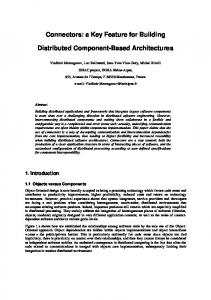
Figure 1: Workflow of the method for DS-based BP analysis. 4
METHOD FOR DISTRIBUTED SIMULATION OF BPs
The method is based on our previous work (Bocciarelli et al. 2012), from which the method inherits the workflow for supporting BP analysis. As shown in Figure 1, the workflow takes as input a PyBPMN model specifying the functional and non-functional BP requirements. Next, the workflow obtains a UMLbased design model that results from the (model-to-model) PyBPMN-to-UML transformation, and consists of a UML Activity Diagram (AD). The use of UML allows both to exploit previous contributions that provide model-driven methods for automatically building performance models (Bocciarelli et al. 2011; Bocciarelli et al. 2012), and also to take advantage of specific UML extensions, called profiles, that provide a standard approach for annotating UML models with domain-specific information.
2555
Bocciarelli, Gianni, Pieroni, and D'Ambrogio The so obtained UML model is given as input to the UML-to-EQN model transformation that derives the EQN model representing the BP simulation model. Such a model is compliant with the EQN metamodel described in Section 4.1. Once this EQN model is available, the workflow continues with the generation of the DS simulator for the BP analysis, using the (model-to-text) EQN-to-jEQN transformation. This transformation derives the distributed simulator coded in jEQN. The simulator can be finally deployed on a SimArch-enabled distributed platform and be run for yielding the results of the BP analysis. Although the above workflow shares several similarities with the one introduced in (Bocciarelli et al., 2012), the proposed workflow differs in four ways: 1) use of an enhanced EQN metamodel for representing the model partitioning over the distributed infrastructure; 2) extension of the UML-to-EQN model-tomodel transformations for specifying EQN subnetworks to be run on independent hosts; and 3) extension of the EQN-to-jEQN transformation for the distributed simulation case. As 1) concerns static aspects, the differences are briefly presented below. Conversely, 2) and 3) concerns dynamic aspects which can be more effectively presented in the example application following this section.
Figure 2: MOF metamodel of EQN. 4.1
EQN METAMODEL
Figure 2 illustrates the EQN metamodel for used for instantiating EQN models of BPs. The metamodel specifies the relationships among EQN entities, such as Source, Service Centers, Waiting Systems, etc. Specifically, the abstract metaclass BaseElement defines the basic element of the EQN metamodel. This metaclass is characterized by the name attribute and by the id attribute, which specify the element name and the unique element identifier, respectively. The EQNModel metaclass represents the root element of the EQN model. As an EQN model is specified in terms of centers and links that compose the queueing network, the metamodel also includes the metaclasses Center and Link, that are connected to the EQNModel metaclass by aggregation associations. For a complete description of the EQN metamodel interested readers may refer to (Bocciarelli et al. 2012).
2556
Bocciarelli, Gianni, Pieroni, and D'Ambrogio Nevertheless, it should be underlined that, as described in Section 1, the model-driven method proposed in this work founds on the EQN formalism to specify the BP performance model and on jEQN language to implement the corresponding distributed simulation. To this respect, as the EQN model constitutes the input of the model-to-text transformation that generates the jEQN code, it must include information needed to drive the generation of the several federates composing the distributed simulation. To this purpose, in order to model the partitioning of an EQN model into several subnetworks, the Subnetwork metaclass has been added to the metamodel. Moreover, as a subnetwork is constituted by a collection of centers and links, the metamodel also includes the aggregation relationships center and link between the Subnetwork metaclasses and the Center and the Link metaclasses, respectively, as illustrated in the portion of Figure 2 bounded by the dotted line. 5
EXAMPLE APPLICATION
The method presentation continues with an example application related to the BP analysis for an ecommerce scenario consisting of a user who browses, selects, and purchases products from an online catalogue. In particular, the following steps are assumed to be performed: 1. the user navigates in the provider’s catalogue and adds the desired items to the basket; 2. the user clicks the checkout button to complete the order and purchase the items; 3. the user specifies the information needed to pay (i.e., credit card number) and to receive the parcel (i.e., address and email contact); 4. the system computes the total cost, including shipment fares, and prepares the bill; 5. the process in charge of providing, preparing and shipping the purchased item is activated. The scenario is inspired by the one in (Bocciarelli et al. 2012), which has been revised also to exploit the new capabilities for the generation of a distributed simulator. Being the paper focused on model building, this section specifically deals with the generation of the EQN performance model and the jEQNbased corresponding implementation, without providing details about the model evaluation activity, which is out of the scope of this paper. Finally, we assume that the product providers interface with the courier for the accurate evaluation of the shipment costs and times. These information can be more accurately be determined by the shipment company through the analysis of the internal processes, which the shipment company may not want to share with the product company. This condition requires that the BP analysis cannot be developed entirely on either the product company site or the shipment company site, and therefore a distributed approach is necessary. The simplicity of this specific scenario may appear not to fully motivate the distributed computational capabilities, which however can be essential in real-world application scenarios consisting of a larger number of tasks, activities and actors participating to the BP. 5.1
Business Process Specification and UML Design Model Generation
At the first step, the functional and non-functional requirements of the BP have to be specified by use of the PyBPMN notation. Specifically, the PyBPMN model represents the functional requirements in terms of the tasks flow, while the performance characterization of each task is expressed by specifying the estimated execution demand. The BP is designed as an orchestration of the following services: a service providing payment services, denoted as Payment Manager (PM) service; a service to manage the stock, responsible for providing and shipping the ordered items, denoted as Stock Manager (SM) service; a service providing billing services, denoted as Billing Manager (BM) service.
2557
Bocciarelli, Gianni, Pieroni, and D'Ambrogio The PyBPMN model is shown in Figure 3. At the second step, the PyBPMN-to-UML model transformation is executed to generate the UML Activity Diagram annotated with SoaML and MARTE profiles, while at the third step, a service discovery is carried out to find a set of concrete services that match the abstract service interfaces specified in the PyBPMN. For the sake of brevity those steps are not further described. For a complete description of such steps, the reader is referred to (Bocciarelli et al., 2012). At the end of the third step, an AD that includes the performance characteristics of the candidate services is available. The next section shows how such a UML model is used to generate the EQN performance model. execDemand = {value=200, unit='ms', source='est', dir='decr', statQ='max'}
execDemand = {value=30, unit='ms', source='est', dir='decr', statQ='max'}
[0.1] CheckOut
PaymentRequest
BillingRequest
[0.9] ShipmentRequest
PaymentManager Service
BillingManager Service
execDemand = {value=250, unit='ms', source='est', dir='decr', statQ='max'}
Stock Manager
Billing Manager
Payment Manager
PurchaseService
execDemand = {value=20, unit='ms', source='est', dir='decr', statQ='max'}
ShipmentManager Service
Figure 3: PyBPMN specification of the checkout process.
5.2
Generation of the EQN Performance Model
The UML-to-EQN model transformation is executed to generate the performance model. Specifically, it maps an input UML AD taken to an output EQN model; such a model transformation has been specified by use of QVT (OMG 2008) and executed by use of MediniQVT (IKV 2011), a tool set for model to model transformations that implements the OMG’s QVT Relations standard. Medini QVT is available both as a self-contained tool and as an Eclipse plugin. The adopted development configuration has been based on the Eclipse plugin. QVT prescribes that both the source and the target models used in a transformation must be instance of a MOF compliant metamodel (OMG 2004). To this respect, the target EQN model is an instance of the EQN metamodel, as described in Section 4.1. The UML-to-EQN model transformation used in this paper has been based on the one proposed in (Bocciarelli et al. 2012). Such transformation has been simply adapted in order to manage the subnetwork element, according to the metamodel shown in Figure 2. More specifically, the UML-to-EQN model transformation has been extended with the following rules, here specified in natural language: 1. map each UML:Swimlane element to a EQN:Subnetwork element 2. in the EQN model, create an aggregation association that connects each EQN:Subnetwork element to the EQN:EQNModel element 3. for each swimlane sw in the UML domain that has been mapped to a subnetwork s in the EQN:
2558
Bocciarelli, Gianni, Pieroni, and D'Ambrogio 3.1 according to the existing rules (see Bocciarelli et al., 2012), map each element in sw to the corresponding element in s; 3.2 in the EQN model, create an aggregation association that connects each element in s to the corresponding EQN:Subnetwork element. The resulting EQN model is shown in Figure 4. The next section describes how the EQN model is used to drive the generation of the jEQN code. release
Subnet 1
set C1
Token Pool [0.05]
...
[C0] [0.5] Orchestrator λ = 0.05
Terminal thinkTime = 5 s nUsers=$
[0.45]
WAN1 λ = 1.05
[C1]
allocate
Payment ServiceCenter λ = 0.00022
set C0
Subnet 2
release set C1
Token Pool
[C0] WAN2 λ = 0.2
[C1]
allocate
Billing ServiceCenter λ = 0.03
set C0
Subnet 3 release set C1
Token Pool
R WAN3 λ = 0.0069
[C0]
[C1]
allocate
Stock ServiceCenter λ = 0.004
set C0
Subnet 4
Figure 4: EQN model and subnet partition. 5.3
Generation of the jEQN-based DS Implementation
Once the EQN UML model has been obtained from the UML-to-EQN transformation, the model can be given as input to the EQN-to-jEQN transformation, to derive the Java coding for the distributed simulator in jEQN. The EQN-to-jEQN transformation, that has been implemented as an XSLT-based model-to-text transformation maps the XML document representing the EQN model to a set of Java files for the distributed simulators and a set of property files for the simulator configuration. In particular, the transformation consists of the following steps: 1. Generation of FederateManager and related HLA data definition 2. Generation of simulation scenario settings 3. Generation of individual jEQN simulators 4. Generation of the batch file to start the Java programs containing the jEQN simulators Step 1 creates the HLA standard FederationManager federate for the coordination of the simulation lifecycle (Kuhl et al. 1999). This steps also produces the HLA configuration files for the federation execution, including the data definition files for the data exchange among the federates. These files are defined in the SimArch project and do not need to be specialized for the specific simulation execution. Step 2 produces the simulation system configuration files, whose templates are already defined in the SimArch
2559
Bocciarelli, Gianni, Pieroni, and D'Ambrogio project and need only to be tailored for the specific scenario. In particular, these files cover the configuration of the HLA environment (e.g., hostname and port number of the HLA server) and of the simulation scenario under investigation (e.g., number of jEQN simulators and simulation length). Finally, step 3 derives the code of individual jEQN simulators, each named after the respective subnetwork ― we implicitly assume that the subnetworks also identify the model partitioning over the distributed environment; and therefore step 3 is to be repeated for each subnetwork. This step consists in two substeps: 3.1. Generation of import statements and Class skeleton 3.2. Generation of main method 3.2.1. Generation of statements for SimArch and jEQN initialization 3.2.2. Generation of statements for the subnetwork’s EQN (local) entities 3.2.3. Generation of statements for the remote stubs for adjancent subnetwork’s EQN entities 3.2.4. Generation of statements for the connections of the declared entities (both local and remote stubs) 3.2.5. Generation of the statements to activate the simulation execution Substeps 3.1 and 3.2.1 are a plain copy operations of existing lines of code in the SimArch and jEQN projects, and therefore they are not discussed further. Please refer to (Gianni et al. 2011) or the SimArch project website for details on these statements. Step 3.2.2 is defined by an iteration on complex mapping statements for the conversion of the above defined UML Classes into the respective jEQN declaration code. This mapping, which can be synthetically defined for the above Classes, needs to be applied to all the EQN Classes composing the EQN subnetwork to be simulated within the jEQN simulator being generated. Concerning the mapping definition, we distinguish between the mapping for the EQN parameters and for the EQN entities. For the EQN parameters, such as QueueSelectionPolicy, SchedulingType, or Distribution; a tabular description of the mapping would be tedious to present, and therefore we present the transformation result for the Orchestrator Queue. #1. NumericStream ns = new ExponentialStream(new JavaSimGenerators(), 0.08); #2. MaskBasePolicy insertionPolicy = new MaskImplicitButNotExplicitInputDependentPolicy(new FIFOEnqueuingPolicy(new ArrayList())); #3. UserQueue userQueue = new InfiniteUserQueue(insertionPolicy, userListImplementation);
Statement #1 defines the pseudo-random sequences for the service request to the Orchestrator Center. The statement uses the JavaSim shuffled generator (http://www.j-sim.org) and the integer uniform sequence in a double exponential one with lambda == 0.08. Statement #2 instantiates the policy for the enqueueing of incoming users into the Orchestrator Queue entity. This statement conforms to the jEQN Policy Framework defined in (Gianni et al. 2008). Finally, statement #3 allocates the data structure for the storage of the incoming users. For the EQN entities, the mapping is straightforward and is outlined in Table 1. As an example, the Orchestrator Queue would lead to the following jEQN line of code: #4. NonPreemptiveWaitingSystem ws = new NonPreemptiveWaitingSystem( new JEQNName("Orchestrator"), timeFactory, layer2Factory, new InfiniteUserQueue( new UserDecisionDataFactory(), insertionPolicy, userListImplementation), new SingleCatServiceRequestGenerator(ns));
2560
Bocciarelli, Gianni, Pieroni, and D'Ambrogio Table 1: Mapping between EQN UML Classes and jEQN Components. EQN UML Class
jEQN Component Source InfiniteServer WaitingSystem PassiveQueue SplitNode JoinNode Router
Terminal Queue Passive Queue Split Node Join Node Router
where the timeFactory and layer2Factory are objects declared in the SimArch and jEQN initialization statements in the above step 3.2.1. Conversely, UserDecisionDataFactory and SingleCatServiceRequestGenerator are two reusable building blocks defined in jEQN. The former is for setting the entire User Class as decision element for the enqueuing. The latter is for the definition of only a category of users for the service request time. The transformation continues with step 3.2.3, which declares local stubs for the remote referenced entities. The entities can be simply identified by following the subnetwork boundary line and mark all the outgoing connections. Each of these connections reaches an EQN entity defined in a subnetwork that will be simulated by a remote jEQN simulators. This EQN entity needs to be locally declared using the following statement: #5. RemoteEntity WAN1 = new BasicRemoteEntity( new JEQNName("Subnet2"), new JEQNName("WAN1")); #6. InPort wan1InPort = new InPort( new JEQNName(WaitingSystem.IN_PORT_NAME), WAN1);
where statement #5 declares the local stub for the remote entity and statement #6 defines the local stub for the remote socket for the same entity. Once all the stubs for the remote entities are defined, the transformation proceeds to step 3.2.4. This steps connects all the above declared entities regardless of their physical definition in the local or remote jEQN simulator. Except for a few conceptual details, this step is achieved by the following statement: #7. BasicLink l = new PointToPointLink(.getOutPort(), .getInPort());
where senderEntityName is the Java name of the above defined jEQN entity from which the connection departs and recipientEntityName is the Java name of the above defined jEQN entity name to which the connection arrives. Finally, step 3.2.5 concludes the definition of the individual jEQN simulator which is now ready for deployment and execution on a distributed platform. Step 4 generates the batch files for execution of the SimArch simulation environment, including the HLA server, the FederationManager and the individual jEQN simulators. These batch files also refer to the above generated properties file for the considered BP analysis scenario. 6
CONCLUSIONS
Simulation is an essential tool for business process analysis as it overcomes the limitations of analytical approaches and integrates with business process models for the specification of real processes. However, new needs are arising for the simulation of business processes as they are gradually becoming more complex and inherently cross the boundaries of multiple enterprises. Specifically, these new needs concern increased computational capabilities and distributed use of business process models and simulators. Differently from local simulation approaches, distributed simulation approaches can be used to fully address 2561
Bocciarelli, Gianni, Pieroni, and D'Ambrogio these needs as they offer increased computational capabilities as well as the remote use of BP models and simulators. However, distributed simulation systems require a further extra development effort and specialized know-how, with respect to local simulation. As a consequence practical barriers exist to the use of distributed simulation for business process analysis. In this paper, we attempt to lower these barriers by introducing a method for the model-driven derivation of a distributed simulation system for business process analysis. The method takes as input a performance-decorated BPMN model and yields as output the Java code of the distributed simulation system based on the jEQN domain specific language and the SimArch architecture, which is built on top of the IEEE HLA standard. REFERENCES Antolin, R.G. and de Lara J. 2008. “A Model-Driven Approach to Service Performance Prediction and Analysis". In Proceedings of the 6th Workshop on System Testing and Validation (STV08), Madrid, Spain. Bocciarelli P. and D’Ambrogio. A. 2011. “A BPMN Extension for Modeling Non Functional Properties of Business Processes.” In Proceedings of the Symposium On Theory of Modeling and Simulation, DEVS-TMS ’11. Bocciarelli P. and D’Ambrogio. A. 2011b. “Performability-Oriented Description and Analysis of Business Processes”. In Business Process Modeling: Software Engineering, Analysis and Applications, Edited by Jason A. Beckmann. Nova Publishers. Bocciarelli P. and D’Ambrogio. A. 2012. “Automated Performance Analysis of Business Processes”. In Proceedings of the Symposium On Theory of Modeling and Simulation, DEVS-TMS ’12. Bolch, G., Greiner, S., De Meer, H., and Trivedi, K. 1998. Queueing Networks and Markov Chains, Wiley. Casati F., Sahai A. 2004. “Business process: Concepts, systems, and protocols”. In Munindar P. Singh, editor, Practical Handbook of Internet Computing. Chapman Hall & CRC Press, Baton Rouge. Douglas C. Schmidt. 2006. Model-driven engineering. IEEE Computer, 39(2). February. Gianni D., and D’Ambrogio, A. 2008 “A Domain Specific Language for the Definition of Extended Queueing Networks Models”, Proceedings of the 2008 IASTED Software Engineering Conference (SE08), Innsbruck, Austria. Gianni, D., D’Ambrogio, A., Iazeolla, G., and Pieroni, A. 2008b. “Producing simulation sequences by use of a Java-based generalized framework”, Proceedings of the 2nd European Modelling Symposium, Liverpool, UK. Gianni, D., D’Ambrogio, A., and Iazeolla, G. 2010. “Ontology-based Specification of Simulation Sequences”, International Journal of Simulation, Systems and Technologies, special issue on Ontology, Modelling and Simulation, UKSim Society, vol. 10, n. 2, pp. 82-93. Gianni, D., D’Ambrogio, A., and Iazeolla, G. 2011. “Software Technologies to Ease the Development of Distributed Simulation Systems”, Simulation: Transactions of the Society for Modeling and Simulation, SCS International, vol. 87, no. 9, pp. 819-836. Gu G. P., Petriu C. D. 2005. “From uml to lqn by xml algebra-based model transformations”. In Proceedings of the 5th international workshop on Software and performance (WOSP ’05), pages 99–110, New York, NY, USA. Iazeolla G., Pieroni A., D'Ambrogio A. and Gianni D. 2010. “A distributed approach to the simulation of inherently distributed systems”. In Proceedings of the 2010 Spring Simulation Multiconference (SpringSim '10). SCSI, San Diego, CA, USA. IEEE . 2000. Standard for Modeling and Simulation (M&S) High Level Architecture (HLA) - frameworks and rules. Technical Report 1516. IKV 2011. ikv++ technologies ag. Medini QVT. http://projects.ikv.de/qvt.
2562
Bocciarelli, Gianni, Pieroni, and D'Ambrogio Kamrani F., Ayani R., Karimson A. 2010. “Optimizing a business process model by using simulation”. In IEEE Workshop on Principles of Advanced and Distributed Simulation (PADS), pages 1–8, Atlanta, GA, May. Kawther Saeedi, Liping Zhao, and Pedro R. Falcone Sampaio. 2010. “Extending BPMN for supporting customerfacing service quality requirements”. In Proceedings of the IEEE International Conference on Web services. Khul, F., Weatherly, R., Dahmann, J. 1999. Creating Computer Simulation Systems: An Introduction to High Level Architecture. Prentice Hall. Litoiu M. 2004. “Migrating to Web services: a performance engineering approach”. Journal of Software Maintenance and Evolution: Research and Practice, vol. 16, pp 51-10. OMG. 2004. Meta Object Facility (MOF) Specification, version 2.0. OMG. 2007. XML Metadata Interchange (XMI) Specification, version 2.1.1. OMG. 2008. Meta Object Facility (MOF) 2.0 Query/View/Transformation, version 1.0. OMG. 2009. A UML profile for Modeling and Analysis of Real Time Embedded Systems, v. 1.0. OMG. 2011. Business Process Model and Notation (BPMN), version 2.0, http://www.omg.org/spec/BPMN/2.0. January Tsai W., Li W., Sarjoughian H., Shao Q. 2011. “SimSaaS: simulation software-as-a-service”. In Proceedings of the 44th Annual Simulation Symposium (ANSS '11). Society for Computer Simulation International, San Diego, CA, USA, 77-86. Yang F., Shen W., Tan W., Ghenniwa H. 2010. “A framework for service enterprise workflow simulation based on multi-agent cooperation”. In Proc.. of the IEEE Int. Conference on Systems, Man and Cybernetics, Istanbul, Turkey, 10-13 October, pages 2587– 2594. AUTHORS BIOGRAPHIES PAOLO BOCCIARELLI is a postdoc researcher at the University of Rome “Tor Vergata”. His research interests include software and systems engineering and business process management, specifically with regards to the areas of modeling and simulation and model-driven development. DANIELE GIANNI is an internal research fellow at the European Space Agency. He received a PhD in computer and control engineering from the University of Rome TorVergata (Italy) and held research appointments at Imperial College and the University of Oxford (UK). His research interests are in the area of modeling and simulation. ALESSANDRA PIERONI is a Ph.D. student at the Enterprise Engineering Department of the University of Rome “TorVergata”, Italy. He received a MD Computer Science from the University of Rome “TorVergata”. Her research interests are in modeling and distributed simulation of complex systems. ANDREA D'AMBROGIO is associate professor at the Enterprise Engineering Department of the University of Roma TorVergata (Italy). His research interests are in the fields of model-driven software engineering, performance engineering, distributed and web-based simulation.
2563