820
IEEE TRANSACTIONS ON INDUSTRIAL ELECTRONICS, VOL. 46, NO. 4, AUGUST 1999
A New Control Scheme for Single-Phase PWM Multilevel Rectifier with Power-Factor Correction Bor-Ren Lin, Member, IEEE, and Hsin-Hung Lu
Abstract— A new control scheme for a single-phase bridge rectifier with three-level pulsewidth modulation is proposed to achieve high power factor and low current distortion. The main circuit consists of a diode-bridge rectifier, a boost inductor, two ac power switches, and two capacitors. According to the proposed control scheme based on a voltage comparator and hysteresis current control technique, the output capacitor voltages are balanced and the line current will follow the supply current command. The supply current command is derived from a dclink voltage regulator and an output power estimator. The major advantage of using a three-level rectifier is that the blocking voltage of each ac power device is clamping to half of the dc-link voltage and the generated harmonics of the three-level rectifier are less than those of the conventional two-level rectifier. There are five voltage levels (0; 6Vdc =2; 6Vdc ) on the ac side of the diode rectifier. The high power factor and low harmonic currents at the input of the rectifier are verified by software simulations and experimental tests. Index Terms—Hysteresis current control, power-factor correction, programmable array logic, three-level rectifier.
I. INTRODUCTION
G
ENERALLY, the low power factor and high current harmonics from the ac mains are the major drawbacks of the diode-bridge rectifier. Inserting an inductor on the ac mains is the simplest approach to improve the current waveform and power factor. However, the current harmonics are still not satisfied for international standards, such as IEC 1000-3-2. Several circuit topologies of the single-phase switching-mode rectifier with two-level pulsewidth modulation (PWM) have been proposed [1]–[5] to reduce harmonic currents and increase input power factor. The circuit topologies in [1]–[3] are based on a diode rectifier followed by a boost, buck–boost, or Cuk converter. The topologies of the single-phase full-bridge [4] and half-bridge [5] rectifiers have capabilities of bidirectional power flow and reactive power control. For high-voltage applications, the switching devices with high-voltage stress are generally required. Multilevel converters [6]–[10] are used for high-voltage high-power applications due to their ability to obtain waveforms with
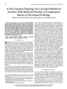
Fig. 1. Circuit configuration of three-level rectifier.
better harmonic spectrum and attain higher voltages with a lower maximum device rating. The three-phase three-level rectifier [11] with unidirectional power flow is proposed to reduce the voltage stresses and power losses on the switching devices. Six power switching devices are used in this topology. In this paper, a simple control strategy based on a lookup table that draws a sinusoidal input current, low current harmonics, and high power factor in the single-phase three-level rectifier is proposed. Two ac power switches are used in the adopted single-phase rectifier to drive the mains current which is following the reference current. The dc-link voltage unbalance problem across two capacitors can be solved by the proposed algorithm based on a voltage balance compensator. The proposed rectifier can be controlled to operate in and two different dc-link voltage ranges, . The complete control schemes are implemented by a digital signal processor (TMS320C50) and a programmable array logic (PAL). The prototype control circuit is implemented in the laboratory to measure the experimental waveforms and verify the proposed control schemes. This paper is organized in the following manner. The system configuration of the proposed single-phase three-level rectifier is discussed in Section II. The operating principle and proposed control algorithm of the three-level rectifier is described in Sections III and IV. The simulation and experimental results are discussed in Section V, followed by a conclusion in Section VI. II. SYSTEM CONFIGURATION
Manuscript received June 24, 1998; revised April 9, 1999. Abstract published on the Internet April 18, 1999. The authors are with the Department of Electrical Engineering, National Yunlin University of Science and Technology, Yunlin 640, Taiwan, R.O.C. (e-mail:
[email protected]). Publisher Item Identifier S 0278-0046(99)05622-1.
The proposed single-phase three-level PWM rectifier consists of a single-phase diode bridge and two ac power switches, as shown in Fig. 1. The rectifier is used to provide two balance dc voltages which are generally needed for a threeis level PWM diode clamped inverter. An inductance
0278–0046/99$10.00 1999 IEEE
LIN AND LU: A NEW CONTROL SCHEME FOR SINGLE-PHASE PWM MULTILEVEL RECTIFIER WITH PFC
placed between the ac mains and the diode-bridge rectifier to minimize the current ripple. A single-phase three-level PWM rectifier connected to the supply line is operated to reduce the ac current harmonics and give a high input power factor. The rectifier control algorithm is based on a lookup table with hysteresis current control to obtain fast dynamic response and ensure that line current follows the reference current with minimum error and delay. The dc-link voltage regulator is used to determine the reference current of the mains. The given variable of the PWM rectifier is the ac line voltage and the control variables are the dc-link voltage, voltage difference between two split capacitors, and the harmonic content of the mains current. III. OPERATING PRINCIPLE Several topologies of a single-phase two-level switchingmode rectifier are proposed to reduce utility current harmonics and increase power factor. A single-phase three-level rectifier is proposed to provide two balance capacitor voltages for three-level inverter applications. The main objectives of the adopted three-level rectifier are drawing sinusoidal current with unity power factor from the ac mains and maintaining balanced dc voltages for stable inverter operation. Fig. 1 shows a single-phase three-level rectifier to feed a split-capacitor dc link which is necessary as a dc source for three-level inverters. Two ac power switches and four fast recovery diodes are used in the adopted rectifier. The circuit operation can be divided into four modes according to the state of two power switches ( and ), and the equivalent circuits are shown in Fig. 2. ) is shown in Fig. 2(a). The first mode ( The absolute value of mains current is decreasing, since the proposed three-level rectifier is a boost rectifier. The corresponding circuit equation is (1) , ) is shown in Fig. 2(b). The second mode ( is In the positive half cycle of the mains, the capacitor charged and the voltage is increasing. The capacitor voltage is increasing in the negative half cycle of the mains. The corresponding circuit equation is (2) or (3) , ), the capacitor or In the third mode ( is charged according to the sign of mains current shown in Fig. 2(c). The circuit equation about this mode is (4) or (5)
821
The absolute value of mains current is increasing in the last mode ( , ), since . The circuit equation is (6) According to the above equations and the states of two power can be expressed as (7) and in switches, the voltage Table I
(7) (close) or 0 (open), 1 or 2. The differential where equations of the adopted PWM rectifier shown in Fig. 2 can be further described as follows according to the state of the power switches and fast recovery diodes being on or off: (8) (9) (10)
(11)
(12) where
if
or
if
.
IV. PROPOSED CONTROL ALGORITHM Two power switches ( and ) can be controlled using a hysteresis or triangular-carrier-wave current controller such that the line current is a sinusoidal wave with low current harmonics. To prevent inrush current from startup operation, an inrush circuit can be added to the rectifier to provide soft-start operation. In order to obtain unity power factor, , and three variables (line current , dc-link voltage ) have to be controlled. dc-link voltage difference The optocouplers are used to sense the dc-link voltage. To , the voltage compensator compensate the dc-link voltage is used to reduce the voltage steady-state error across the capacitors. For balancing the active power flow between the ac mains and the dc link and improving the dynamic response due to load change, the reference line current is further controlled by adding the signal from the output power estimator. The sinusoidal time function from the phase-locked
822
IEEE TRANSACTIONS ON INDUSTRIAL ELECTRONICS, VOL. 46, NO. 4, AUGUST 1999
(a)
(b)
(c) Fig. 2. Four equivalent circuits of the adopted rectifier. (a)
TABLE I RELATION BETWEEN THE VOLTAGE va b
AND THE
(d) S1
=
S2
=0
SWITCHING SIGNALS
:
(b)
S1
= 1; S2 = 0: (c) S1 = 0; S2 = 1: (d) S1 = S2 = 1:
loop is multiplied by the amplitude of the command current to form the reference current. The phase-locked loop is adopted ) which is in phase with to produce a sinusoidal function ( lookup table is stored in an the ac source voltage. The electrically programmable read-only memory (EPROM). The EPROM contents pass through a digital-to-analog converter in order to produce a sinusoidal time-function output. The amplitude of the command current is coming from the addition of the output power estimator and the dc voltage compensator.
LIN AND LU: A NEW CONTROL SCHEME FOR SINGLE-PHASE PWM MULTILEVEL RECTIFIER WITH PFC
TABLE II RELATIONS BETWEEN THE SWITCHING SIGNALS (S1 , S2 ) AND CONTROL SIGNALS (b1–b4) FOR THREE-LEVEL PWM RECTIFIER
The command reference current
823
TABLE III TRUTH TABLE OF THREE-LEVEL PWM RECTIFIER
the current hysteresis comparator is 1 ( ). One should . One way to then increase the line current, since increase the mains current is to set two ac power switches ( , and . In this case, there are no charge is less than . actions on both capacitors, since , , In the case of similar digital control signals ( , and ), two ac power switches ( , ) can be , decrease the mains assigned to be (1, 0) to force . The control switching current, and charge the capacitor table (Table II) can be rewritten as a truth table (Table III). The following equations can be derived from a Karnaugh map for expressing the relations between the state of two ac power and digital signals – : switches ,
is (13)
and and are the proportional where and integral feedback gain of the dc voltage regulator. The is used to represent the positive half cycle digital signal ) or negative half cycle ( ) of the ac source ( between current . In order to produce the dc-link voltage and in the adopted three-level PWM rectifier, the following four digital signals are defined as (14)
(15)
(16)
.
(17)
The hysteresis current controller is adopted to force the ac mains current to be a sinusoidal wave which has low harmonic currents and is in phase with the mains voltage. The switching and are generated from signals of power switches the control switching table (Table II) which address signals coming from the sign of the mains current ( ), the output of the hysteresis current comparator ( ), the voltage comparator of two split capacitors ( ), and the comparison of source and ( ). If the source voltage and minimum voltage of ), capacitor voltage is larger than current is positive ( ( ), magnitude of instantaneous mains voltage is less and ( ), and output of than minimum voltage of
(18)
(19) These two equations can be implemented by a PAL (PEEL 18CV8) to simplify the control circuit. If two capacitor voltand , are equal, then there is a three-level PWM ages, /2) on the waveforms of and pattern ( /2, 0, and and a five-level PWM pattern ( , /2, 0, /2, and ) on the waveform of . The three-level PWM by the adopted rectifier is generated to reduce the total harmonic distortion (THD) of the PWM waveform. The adopted rectifier configuration can also be operated by general two-level PWM modulation techniques. The first modulation technique for two-level PWM is the boost rectifier. In is controlled this modulation technique, the dc-link voltage . Two ac power switches are closed to be greater than . There are two equivalent or opened together, i.e., circuits according to the state of the power switches shown in Fig. 2(a) and (d). In the modulation technique of the two-level PWM boost rectifier, the general differential equation of the equivalent circuit is (20) At the positive half cycle of the mains, the switches are closed or opened to increase or decrease the ac source current. On the other hand, the switches are closed or opened to decrease or increase the ac source current at the negative half cycle of
824
IEEE TRANSACTIONS ON INDUSTRIAL ELECTRONICS, VOL. 46, NO. 4, AUGUST 1999
TABLE IV RELATION BETWEEN THE SWITCHING SIGNALS (S1 , S2 ) AND CONTROL SIGNALS (b1–b2) FOR TWO-LEVEL PWM BOOST RECTIFIER
TABLE V TRUTH TABLE OF TWO-LEVEL PWM BOOST RECTIFIER
TABLE VI RELATION BETWEEN THE SWITCHING SIGNALS (S1 , S2 ) AND THE CONTROL SIGNALS (b1–b3) FOR TWO-LEVEL PWM DOUBLE BOOST RECTIFIER
Fig. 3. Control blocks of the single-phase PWM rectifier.
TABLE VII TRUTH TABLE OF TWO-LEVEL PWM DOUBLE BOOST RECTIFIER
the mains. Let us assume that equals 1 if the mains is at the equals 1 if the slope of the source positive half cycle and current is positive. Only two digital control signals ( and ) are used in this modulation technique. The control lookup table between the state of two ac power switches and the condition of the ac source current and the current hysteresis comparator is shown in Table IV. A simple truth table of this modulation technique is shown in Table V. The relation between the state of the two ac power switches and two logic signals is expressed as (21) This simple expression can be implemented by basic logic gates. The disadvantage of the two-level PWM modulation technique is that the balancing problem of two capacitor voltages is not controllable. Another modulation technique is adopted to control the two-level PWM double boost rectifier. In this modulation technique, each capacitor voltage is controlled to be greater . The voltage unbalance problem can be improved than
Fig. 4. Control lookup tables implemented by a PAL and multiplexer.
by using this control scheme. The equivalent circuits of this two-level PWM double boost rectifier are the same as that of a three-level PWM rectifier. Three digital control signals ( , , and ) are used in this modulation technique. The digital signal is not used in this modulation, since is and . The control lookup table between always less than the state of two ac power switches and the conditions of line current and the difference between two capacitor voltages is shown in Table VI. This lookup table can be further simplified to be a truth table (Table VII). The following two equations can be derived using the Karnaugh map: (22) (23)
LIN AND LU: A NEW CONTROL SCHEME FOR SINGLE-PHASE PWM MULTILEVEL RECTIFIER WITH PFC
(a)
825
(b)
(c) Fig. 5. Simulation and experimental results of the three-level rectifier. (a) Simulated waveforms. (b) Control and switching signals (time: 2 ms/div). (c) Measured waveforms.
The complete control block for the adopted rectifier configuration is shown in Fig. 3. The lookup tables of the three proposed modulation techniques (three-level PWM rectifier, two-level PWM boost rectifier, and two-level PWM double boost rectifier) are implemented by a PAL, as shown in Fig. 4. The control algorithms in the above discussions are easy to implement by using the analog circuit or digital controller, such as the 80196MC or TMS320C50.
V. SIMULATION AND EXPERIMENTAL RESULTS In order to verify the proposed control algorithm, the control scheme of the single-phase multilevel rectifier has been
implemented by the digital signal processor TMS320C50. The optocoupler, current transducer, and potential transformer are used to measure dc-link voltage, mains current, and voltage. The dc voltage compensator and PWM signals of two ac power switches according to Tables III, V, and VII were implemented by the digital controller. The hysteresis current control was adopted to improve the dynamic response due to the load change. The input source voltage is 110 V . The input inductance is about 1.5 mH. The ac power switches are implemented by power MOSFET IRFP450. The capacitance of the two capacitors is 2200 F. The output rated power is 1200 W at the laboratory tests. The average value of the switching frequency for the rectifier operation is about 10 kHz,
826
IEEE TRANSACTIONS ON INDUSTRIAL ELECTRONICS, VOL. 46, NO. 4, AUGUST 1999
(a)
(b)
(c) Fig. 6. Simulation and experimental results of the two-level boost rectifier. (a) Simulated waveforms. (b) Control and switching signals (time: 2 ms/div). (c) Measured waveforms.
and the range of variation is about 3 kHz in the laboratory tests. The dc voltage is 200 V in the three-level rectifier and two-level boost rectifier or 400 V in the two-level double boost rectifier. Fig. 5 shows the simulated and experimental waveforms of the proposed three-level PWM rectifier. There and , and a is a three-level PWM pattern on voltage . Figs. 6 and 7 give the five-level PWM pattern on voltage simulated and experimental waveforms of the two-level PWM boost rectifier and double boost rectifier. To investigate the dynamic response of the three-level PWM rectifier with and without power estimator, the load change between 600–1000 W were tested and shown in Fig. 8(a)–(d). The decreasing
or increasing voltage on the dc link due to load change is about 15 V and recovery time is about 0.7 s using the control algorithm with a power estimator. For the control algorithm without a power estimator, the voltage variation on the dc link due to load change is about 35 V and recovery time is about 1.5 s. Fig. 8(e) shows the steady-state performance (THD of line current, input power factor, and converter efficiency) of the proposed three-level rectifier. The power factor is close to unity, THD is close to 6%, and converter efficiency is close to 0.92 at the rated power (1200 W). To briefly compare three different modulation techniques, the THD of the mains current is measured and shown in Fig. 9. The current THD of the
LIN AND LU: A NEW CONTROL SCHEME FOR SINGLE-PHASE PWM MULTILEVEL RECTIFIER WITH PFC
(a)
827
(b)
(c) Fig. 7. Simulation and experimental results of the two-level double boost rectifier. (a) Simulated waveforms. (b) Control and switching signals (time: 2 ms/div). (c) Measured waveforms.
three-level PWM modulation technique is smaller than that of the other two modulation schemes. The measured waveforms of the voltage difference between two capacitors and the dclink voltage in the case of a slight unbalance of the load are shown in Fig. 10. The voltage difference between two capacitors is small based on experimental results.
VI. CONCLUSIONS Three modulation techniques of a single-phase multilevel rectifier have been proposed in this paper. The control schemes are based on the lookup tables with the aid of a hysteresis current controller. The input power factor and current harmonics
based on the proposed control schemes are improved based on experimental results. The simulation and experimental results show good line current waveform with nearly unity power factor and low harmonic distortion. The voltage unbalance problem is improved by using the proposed control algorithm. The blocking voltage of each switching device is clamping to half of the dc-bus voltage. The control algorithms are simple and easy to implement by the analog circuit or digital controller. The dynamic performance is good enough for fast recovery of the dc-link voltage due to load change. The applications of the adopted single-phase multilevel rectifier can be used as an input stage of diode clamped multilevel inverter.
828
IEEE TRANSACTIONS ON INDUSTRIAL ELECTRONICS, VOL. 46, NO. 4, AUGUST 1999
(a)
(b)
(c)
(d)
(e) Fig. 8. Dynamic response of the three-level PWM rectifier. (a) 600–1000 W with power estimator. (b) 600–1000 W without power estimator. (c) 1000–600 W with power estimator. (d) 1000–600 W without power estimator. (e) Steady state performance.
Fig. 9. Comparison of line current THD for three modulation techniques.
0
Fig. 10. Measured voltage waveforms of v1 v2 and unbalance of the load (il1 3:8 and il2 = 4:2 A).
=
Vdc
under slight
LIN AND LU: A NEW CONTROL SCHEME FOR SINGLE-PHASE PWM MULTILEVEL RECTIFIER WITH PFC
REFERENCES [1] J. C. Salmon, “Techniques for minimizing the input current distortion of current-controlled single-phase boost rectifiers,” IEEE Trans. Power Electron., vol. 8, pp. 509–520, Oct. 1993. [2] B. R. Lin and T. S. Huang, “Single phase rectifier with high power factor in continuous and discontinuous conduction mode,” in Conf. Rec. IEEE ISIE’95, 1995, pp. 421–426. [3] I. Barbi and S. A. Oliverira, “Sinusoidal line current rectification at unity power factor with boost quasiresonant converters,” in Conf. Rec. IEEE APEC’90, 1990, pp. 553–562. [4] R. Wu, S. B. Dewan, and G. Slemon, “A PWM AC–DC converter with fixed switching frequency,” IEEE Trans. Ind. Applicat., vol. 26, pp. 880–886, Sept./Oct. 1990. [5] J. T. Boys and A. Green, “Current-forced single-phase reversible rectifier,” Proc. Inst. Elect. Eng., vol. 136, pt. B, no. 5, pp. 205–211, 1989. [6] A. Nabae, I. Takahashi, and H. Akagi, “A new neutral point clamped PWM inverter,” IEEE Trans. Ind. Applicat., vol. 17, pp. 518–523, Sept./Oct. 1981. [7] R. Menzies, P. Steimer, and J. Steinke, “Five-level GTO inverters for large induction motor drives,” IEEE Trans. Ind. Applicat., vol. 30, pp. 938–943, July/Aug. 1994. [8] F. Peng, H. Akagi, and A. Nabae, “A study of active power filters using quad-series voltage-source PWM converters for harmonic compensation,” IEEE Trans. Power Electron., vol. 5, pp. 9–15, Jan. 1990. [9] L. Walker, “10MW GTO converter for battery peaking,” IEEE Trans. Ind. Applicat., vol. 26, pp. 63–72, Jan./Feb. 1990. [10] B. Suh and D. Hyun, “A new n-level high voltage inversion system,” IEEE Trans. Ind. Electron., vol. 44, pp. 107–115, Feb. 1997. [11] Y. Zhao, Y. Li, and T. A. Lipo, “Force commutated three level boost type rectifier,” IEEE Trans. Ind. Applicat., vol. 31, pp. 155–161, Jan./Feb. 1995.
829
Bor-Ren Lin (S’91–M’93) received the B.S. degree in electronic engineering from National Taiwan University of Science and Technology, Taipei, Taiwan, R.O.C., in 1988 and the M.S. and Ph.D. degrees in electrical engineering from the University of Missouri, Columbia, in 1990 and 1993, respectively. From 1991 to 1993, he was a Research Assistant in the Power Electronic Research Center, University of Missouri. He is currently an Associate Professor in the Department of Electrical Engineering, National Yunlin University of Science and Technology, Yunlin, Taiwan, R.O.C. His fields of interest are power-factor correction, PWM inverters, active power filters, switching-mode power supplies, ac machine drives, and digital control. He has authored more than 70 published technical conference and journal papers in the area of power electronics.
Hsin-Hung Lu received the B.S. and M.S. degrees in electrical engineering in 1997 and 1999, respectively, from National Yunlin University of Science and Technology, Yunlin, Taiwan, R.O.C., where he is currently working towards the Ph.D. degree. His research interests are resonant converters, power-factor correction, multilevel converters, active power filters, and ac machine drives.