2006 International Conference on Power System Technology. A new distributed power flow algorithm between multi-control-centers based on asynchronous ...
2006 International Conference on Power System Technology I
distributed power flow algorithm between multi-control-centers based on asynchronous iteration
A
new
Zhang Haibo, and Zhang Boming, Senior Member, IEEE, and Sun Hongbin, member, IEEE, and Ao Ran state variables of overlapping area be equal. For the distributed OPFr12-19], most of the algorithms presented in the literature are based on some optimization theory, which can decompose a global optimal problem into several optimal subproblems, to realize regionally distributed optimal flow calculation. Both of these two fields only deal with a snap shot of a static power flow instead of the system state simulation under a branch outage or/and a disturbance on power injection in external systems. The practical dispatching operation simulation in a sub-system needs a distributed calculation of power flow or static security analysis, but in this basic field, distributed power flow calculation based on asynchronous iteration is rarely seen in the literature. Whereas, some helpful discussion on characteristic of distributed calculation can still be found in the literature. Reference[1] points out that synchronous iteration algorithm is not suitable for distributed calculation on WAN for the reason that every iteration step needs time to wait, instead of which asynchronous iteration is a better choice. Reference[7] analyzes some special requests under distributed calculation circumstance and indicates that a considerable advantage of the presented algorithm in [7] is that sub-system can calculate independently. For the distributed calculation based on Index Terms asynchronous iteration, distributed power flow, asynchronous iteration mode, to calculate independently, distributed static security analysis, decomposition and every sub-system needs to set reference node individually. But at the same time, it is hard to accord with the restriction that cooperation, multi-area interconnected system the same boundary node voltage phase angle between subI. INTRODUCTION systems must be equal. Reference [5] takes advantage of the fact that for all the same nodes in overlapping area between Now, researches on distributed energy management difference of the voltage phase angle estimated sub-systems, system(DEMS) are mainly focused on the distributed in each sub-system should be equal in theory, as respectively state estimation(SE) and optimal power flow(OPF). Both of well as to the phase angle difference of their reference equal them mainly use asynchronous iteration mode with the limit of nodes. the average phase angle difference in By calculating current wide area network(WAN) communication condition. each area to revise the phase angle from other overlapping Study on the distributed SEO-9] is usually based on the natural the that different sub-system selects sub-systems, problem decomposition characteristic of SE in geography, firstly reference node is properly solved. Since there is individually calculate the state estimation of sub-system in local, and then no need to have to wait coordination layer's disposal, the by exchanging the boundary information make the boundary method is much suitable for asynchronous iteration calculation. This paper takes in some skills of distributed SE and OPF This work was supported by Special Fund of the National Priority Basic in the literature and analyzes in theory how to utilize the Research of China (2004CB217904) Zhang Haibo and Ao Ran are with the Department of Electrical Thevinan equivalence and its correction calculation for Engineering, North China Electric Power University, Beijing, China (e-mail: external network to realize distributed power flow calculation zhboa ncepu .edu.cnl). Zhang Boming and Sun Hongbin are with the Department of Electrical based on asynchronous iteration mode. The paper provides detailed steps of distributed calculation, establishes agent Engineering, Tsinghua University, Beijing 100084, China Abstract In order to implement a distributed calculation of power flow and static security analysis in distributed EMS(DEMS), a new distributed dynamic power flow algorithm based on asynchronous iteration for multi-area interconnected system is presented in this paper. Based on online tracing Thevinan equivalence for exterior-network, the proposed algorithm can follow the change on system state and give a consistent result with power flow calculation for whole power system. Constructing a fix-point iteration scheme about boundary state variable, the proposed method gradually corrects equivalent injection power of exterior-network to match the power flow result for each sub-system with that for whole system. Some measures are adopted to assure that the accustomed modeling methods for sub-systems can be maintained. The outstanding feature of this method is the independence of load flow calculation for each sub-system. That means, a sub-system can give an acceptable local power flow result even when the distributed calculation can not be performed. Any sub-system can join into or move back from the distributed calculation scheme. So, this method is very suitable for the application of DEMS under recent condition of data exchanging between control centers. Since the network equivalent information has been tracked during the calculation, the algorithm has a good convergence, which has been testified by an example of IEEE-118 system and a real-life system.
1-4244-0111-9/06/$20.00c02006 IEEE.
2
mechanism for coordination layer at each step of algorithm realization, and realizes a completely asynchronous iteration calculation. For the application of asynchronous iteration mode , sub-systems can calculate power flow or static security analysis independently, which is much suitable for
DEMSr2O]
II. THEORETIC ANALYSIS FOR DISTRIBUTED POWER FLOW CALCULATION BASED ON ASYNCHRONOUS ITERATION MODE
In practical system, if each sub-system only generally sets up its external network simplification model in base case, when disturbed, because network equivalence error is inevitable, there will be some errors for the calculated system state variables in sub-system compared with the whole network calculated results, which is indicated at the same boundary nodes between two sub-systems as followed
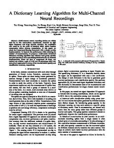
could not know how to correct them. However, if we take Thevinan equivalent method instead of Norton equivalence, since the Thevinan equivalent node voltages can be substituted by boundary node voltages and these boundary node voltages can be corrected by local power flow calculation, it is easier to achieve an escalating response precision of external network equivalence by using Thevinan equivalent correction than Norton. Followed is the detailed analysis of realization of Thevinan equivalent correction. In linear model, if we only want to calculate voltage Ui at boundary node i, we can simplify the two subsystems connected by node i by Thevinan equivalence method to node i, as shown in fig. 1
X(O) B # X(O)(*) B
XB) is the initial values of boundary state variables calculated by local power flow and X(O)(*) is the initial values of the same boundary node state variables calculated in other subsystems. If we want to obtain the same power flow results with the whole network in local sub-system, the boundary restriction needs to be satisfied XB
=
X(*)
Fig. 1 calculation of boundary nodes voltage
In Fig., voltage of boundary node i can be calculated as followed Ujeq jUeq
1+2 zleq zeq
Ui~~~~
(1)
Equation (1) means that the same boundary node state variables calculated independently in each sub-system must be equal, which is the key to accomplish distributed calculation. XB and XB) are respectively from the independent power flow results in different sub-systems. When internal network condition is fixed, the sub-system power flow result is decided by external network equivalent injection power S orS (*) BE
BE
Therefore, we can continuously correct SBe and Seq(*) by data BE
BE
exchanging between sub-systems to get exact values of XB and XB) . It means to correct continuously external network equivalence for each sub-system by data exchanging, so that the changing external network equivalent model can give a right respond to the disturbances occurred in sub-system. Since Ward equivalence in essence belongs to Norton equivalence, when disturbances happened in practical system, corrections for equivalence can be processed by correcting equivalent boundary injection values. A conventional thought is that the corrections for equivalent boundary injection power should be calculated by other sub-systems and then send it to local sub-system. There is on doubt that this method of directly correcting Norton equivalence can escalate precision of equivalence and eventually obtain the whole network calculation effects, but it is difficult to be realized. First of all, the correcting calculation for equivalent injection power is mass; and next, it is hard to get an equivalent injection power correction by other sub-systems because other sub-systems
zeq
+
1
In (2),
_,-
U + 42 U2e 1lq e
(2)
zeq
2
41, 42 are combination parameters and satisfy =1
41 + 2
1($l
> °, 2 > 0)
In non-linear model, when disturbed, sub-system's Norton equivalent current or Thevinan equivalent voltage can't be calculated in base case directly, so we can't use the method similar to (2) to calculate directly the boundary node voltage after disturbed, instead of which only can get results by means of iterative mode. When calculation condition of internal network in subsystem Si is confirmed, the independent power flow results
XI and xB can be regarded as a function of injection power
SeqBE at exterior boundary nodes ,,
I
=
''
' RE!-q
(3)
In (3), 50(.) indicates the local power flow in sub-system. We can regard each sub-system's boundary state variables XBB~ calculated from Seq(O) BE in base case as the initial value of
Thevinan equivalent voltage. It, together with sub-system's own equivalent internal impedance, composes this subsystem's initial Thevinan equivalence on boundary node i. Referring to Fig.1 and using (2), by initial linearization, the boundary node voltage can be calculated, noted as XB) However, because of equivalence error,
-0) calculated by
3
initial linearization is not the genuine value XB of boundary state variable after disturbed but
XB1) is more close to
XB than xB Injection power at each subsystem's exterior boundary node can be calculated by the new interior and exterior boundary node state variables, that's, we can calculate each sub-system's new external network equivalent injection power Seq(l) by B'). Then according to (3), calculate B2) from
5q(l)B
take each sub-system's X2) as its corrected
Thevinan equivalent voltage, then use (2) to calculate X(2) Repeat this process, correct continually each sub-system's Thevinan equivalence and finally we can obtain the genuine boundary node voltage value XB This iteration mode can be expressed as followed -(k+l) XB
_
(k+l) +
IXB
=
FX
(k+l)(*)
(Seq(k)+ 20()) Seq(k)(*))
'10)(fBE (XB )) + 42(*) In (4),
(fBE
(4)
(XB)B))
Seq(k)(*) is other sub-system's equivalent injection
power at exterior boundary nodes;
0( )( )
indicates the power
system's local power flow calculation, which is completely the same with the independent flow calculation performed by control centre on current traditional network model. The distributed algorithm, only both before and after local power flow calculation, adds some equivalent information calculation and data exchange processing, thus it can reserve current control centre's traditional network model. The modification is so little for present computation program that the algorithm is very convenient for practical application. With the increasing of exterior iteration times, calculation precision of sub-system will rise up continuously, until consistent with the calculating results on the whole network. So, by setting different exterior iteration times, the precision of distributed calculation can be controlled, which is very flexible and convenient. III. SOME TECHNIQUES OF ALGORITHM REALIZATION
A. Each sub-system selects reference node individually In order to select reference node individually for each subsystem taking part in distributed calculation, we take measures, similar to that described in [7], to correct boundary node voltage phase of other sub-systems inputted by coordination level. Now, take two sub-systems S1 and S2 for example, the same boundary node voltage phase angles calculated in S1 and S2 respectively will have an equal angle difference,
flow calculation in other sub-system. fB (A) and JB( (.) are the injection power equations at exterior boundary nodes in local and other sub-system respectively. From (4), it can be a12 So, before combining calculation of voltage phase angle seen that, by constructing the fixed-point exterior iteration about XB continually correcting equivalent injection power at in local sub-system S1, we can use U12 to correct the sub-system's exterior boundary nodes during the iteration boundary node phase angles from S2, and a12 is the process, when the iteration is converged at last, we can get calculated average angle difference between the two subXB = XB ) That means, compared with the whole network systems' overlapping boundary node voltage phase angle. calculation, the same calculation results in local sub-system Supposing the set of the same boundary nodes between S1 and S2 , noted as B12, has n nodes. In S1, the input phase are obtained The iteration mode constructed by (4) is called exterior angle correction method during each exterior iteration step can iteration, for it performs a local independent power flow be shown as followed. calculation in each iteration step, and the local independent -d(k) 1 z ((k) _2(kf)) power flow in each sub-system is called interior iteration. (5) Y 12 E ( il 12(in)) n zEB12 in (4) is gotten by data exchanging between sub-(k) - O(k) O(k) (6) 12 systems, this shows, only exterior iteration need coordination B2 B2 (in) in between sub-systems, the power flow calculation local subthe where, 0(32k)(in) is the input phase angle from S 2 duringgth system keeps relative independence all the time. The exchanged variables XBk+l)(*) in exterior iteration does not k-th exterior iteration step and 0(k) is the corrected input need to be calculated in coordination layer, and in each phase angle, the latter can be used to calculate combined exterior iteration step, local sub-system and other sub-systems boundary node voltage phase angle directly in Si . The need not wait synchronously for the coordination layer's disposal, so this algorithm is called distributed power flow correction procedure of input voltage phase angle in S2 is the based on asynchronous iteration mode. same as in Si . From the realization principle of distributed power flow based on asynchronous iteration mode, it can be seen that this B. The disposal of unbalance power algorithm is based on Thevinan equivalent correction for When a disturbance occurred in network leads to active external system. The interior iteration of this algorithm is sub- power unbalanced, dynamic power flow calculation of the
XBk+l)()
4
whole network is to make unbalance active power distributed on all the nodes of system in proportion. For example, the number of all nodes of the whole system is N, the distributed coefficient of the i-th node is , and has
,A
N
")q =1I
(7)
i=l
B'-'
B'- EE.E PE(13 ~~~~~(13) A=PRE P=-BBEE in (13), suffix E represents external network nodes, and suffix BE represents exterior boundary nodes. Matrix B' represents the nodal admittance matrix in DC power flow. pi can be calculated as followed.
-IP
(14) Pi = As long as unbalanced power distribution satisfies (7), the result of dynamic flow calculation has no relation to the j= selection of balance node. When there are m sub-systems participating in the distributed calculation, the proportion of Interior iteration, for each sub-system, performs according unbalanced active power of entire system distributed to sub- to the normal dynamic power flow algorithm, but ,8i (the system S1 is unbalanced active power distributed coefficient within the range of entire network nodes) needs to be disposed unitarily (8) as, = E Ai within local sub-system Sj, that is iEsi The actual unbalanced active power in sub-system (15) = pi Sj (excluding exterior boundary nodes) is
A
AP = YAP ieS
(9)
Where:
A-P
=
PGi - PDi - Ui
PGi, PDi
E
jEi
Uj (Gij cos 01, + Bij sin 01,)
represent active power injection and load of node i
respectively, and Gij, Bij are relevant elements of nodal
In (15),
f,
Si is sub-system's interior unbalanced active
power distributed coefficient, and has E ,
= 1. Since the
exterior boundary nodes have been considered in exterior iteration, so in local dynamic power flow, has PBE = 0.
IV. COORDINATION LAYER PLAY AN AGENT ROLE When several sub-systems participate in distributed calculation, if every sub-system exchanges information directly with other sub-systems, it will cause the whole m distributed calculation too complicated to be realized. So, ZAP, (10) APS= j=1 multi-systems distributed calculation needs a coordination here, the unbalanced active power distributed to subsystem layer to manage the communication between sub-systems. Each sub-system only contacts with coordination layer should be directly. First, coordination layer collects and analyzes the I~~~~ AP, =acx *APs (11) information coming from each sub-system, draws out useful information for each sub-system, and then sends them to the During the exterior iteration, the dispersion between sub-systems. Because the coordination layer plays an agent actual unbalanced active power and its deserved share for sub- role in distributed calculation, it shields the reticula system S should be compensated by equivalent injection at relationship between sub-systems, local sub-system only exterior boundary nodes. Assuming that the number of needs to pay attention to input and output interface with exterior boundary nodes in is 1, at the k-th iteration step, coordination layer. As the flow chart shown in Fig.2, the whole flow process the correction equation about equivalent active power of distributed power flow based on asynchronous iteration injection at exterior boundary node i is mode can be divided into three periods. -~,Ak- APk pk+1_=pk i) real-time equivalence. A PBE. i = BE i + (M ) Firstly, each sub-system constructs a local independent (12) calculation model including the equivalent external network. k =PBE .i + pCi (aCsi E AP, k-Apk) j Coordination layer needs to establish the equivalent network j=1 model of entire network just remaining all the tie-lines, whose In (12), is a proportional coefficient, it is decided by equivalent parameters are provided by the internal network the equivalent unbalanced active power distributed coefficient equivalence calculation in each sub-system. When coordination layer receives internal network equivalent at exterior boundary nodes of which is shown as parameters of each sub-system, it will match them on-line
admittance matrix in subsystem Sj. At the end of each exterior iteration step, the unbalanced active power of the whole system is
Si
Si
pi1
Si,
5
with the equivalent model in coordination layer, then calculate the external equivalent parameters for each sub-system and send them back to the sub-systems to join the local power flow calculation. External network equivalent parameters which need to be calculated in coordination layer include the equivalent branch parameters between exterior boundary nodes of each sub-system and the equivalence of external network unbalanced active power distributed coefficients to its boundary nodes. ii) Asynchronous iteration initialization At this step, sub-system should work out combination parameters at boundary nodes in the overlapping area between sub-systems. Now the role of coordination layer is to dispatch the diagonal elements, corresponding to boundary nodes, of local network node impedances matrix from one sub-system to another sub-system which needs the diagonal elements of impedances to calculate combination parameters in local. iii) Asynchronous iteration,
During asynchronous iteration period, at each iteration step, coordination layer puts the asynchronous iteration calculation information, received from other sub-systems, into a given local storages which serve as the sub-system's input buffer. The asynchronous iteration calculation information includes relevant sub-systems' boundary node voltage, their unbalanced active power and their convergent flag. When a sub-system sends its own iteration information to coordination layer, it also can directly get back the asynchronous iteration information by reading its input buffer in coordination layer, so that there is no need to wait for coordination layer's disposal. During this period, sub-system gets data from coordination layer on its own initiative, even if the data gotten from coordination layer have not been updated or just partly done, sub-system's local power flow calculation can still proceed. Therefore, at each iteration step, sub-systems do not have to wait each other synchronously.
Coordination layer M Sub-system Si Fig.2 Distributed power flow calculation flow chart based on asynchronous iteration mode
The agent role of coordination layer in above three periods is mainly shown in that it has shielded the reticula relationship of data exchanging between sub-systems. For example, during real-time equivalence period, coordination layer substitutes for the calculation of each sub-system's external network equivalent parameters. If there is not a coordination layer in possession of entire network information, sub-system will be hard to get correct external network equivalent parameters. During asynchronous iteration initialization period, transmission of data between sub-systems becomes easier by the agent of coordination layer. During asynchronous iteration period, the agent role of
coordination layer is shown in data transfer-storage, for a sub-system, coordination layer distinguishes the information coming from other sub-systems, seeks out data for its calculation and then puts the data in the input buffer storage for the sub-system. At each exterior iteration step, when the sub-system finishes the local power flow calculation, it can immediately and remotely access the data of corresponding input buffer storage in coordination layer, and then goes on next iteration step without waiting for other sub-systems' disposing synchronously, so, it can achieve the purpose of asynchronous iteration calculation.
6 V. EXAMPLES
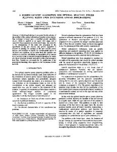
A. IEEE-118 system Take IEEE-1 18 system for example, set branches (15-33), (19-34), (30-38), (23-24), (70-74), (70-75), (75-69), (77-69), (68-81) as tie lines so that this system is divided into three individual sub-systems S1, S2, and S3, as shown in Fig.3:
l
Q1 Q-
5H a)
33
Cu:
traced in Fig.4 indicate the largest error of voltage amplitude of each sub-system in each exterior iteration step, compared with the whole network power flow result.
23
-K7
24
I7--
s3Mdv
0 1 2 3 4 5 6 7 times of exterior iteration
Sub-system S
38
N--
s lMdv s2Mdv
0
__L34L
__7
u:
0. 03 0. 025 0. 02 0. 015 0. 01 0. 005
77 74
,\
70
r