137
A Parametric Voxel Oriented CAD Paradigm to Produce Forming Components for Stretch Formed Jewelry Vishal Gulati1 and Puneet Tandon2 1
G. J. University of Science and Technology, Hisar, India,
[email protected] Indian Institute of Information Technology, Design and Manufacturing, Jabalpur,
[email protected]
2
ABSTRACT This paper proposes a unique kind of jewelry, called stretch formed jewelry. The paper presents a parametric voxel oriented approach to produce stretch forming components that are dies and punches having different patterns of designs. Stretch formed jewelry is created on thin sheet metals (gold or silver) on top of which design patterns are embossed with die and punch tools by stretching the sheet metal beyond elastic limit. Voxels are predefined small structural elements for which the user defines the key parameters. Parametric voxels can be varied during the design process and are joined together to create the design model by the use of rules. Computer-Aided Design (CAD) in conjunction with Rapid Prototyping (RP) machine generates forming tool components. Keywords: Jewelry, CAD, parametric, voxel, Rapid Prototyping.
1. INRODUCTION Jewelry designing is evolving as an area where CAD and RP technologies are extensively used. CAD in conjunction with RP machine can generate designer items [5]. All modern CAD systems are capable of converting three dimensional solid models into STL format, which can be passed on directly to rapid prototyping machines. These systems demonstrate how creativity and imagination can be perfectly harmonized for personnel embellishment. With CAD system, jewelry designing is very simple and less time consuming when compared to manual designing. It capitalizes the advantages of computer over hand, and more complex designs can be generated. It assists in realistically rendering of model from various view points and giving the user an understanding of final result. It also assists in drawing two dimensional comprehensive entities (line, arc, circle etc.) and applying unary (transformations) and binary operations (union, subtraction, intersection etc.). Editing and redesigning facilities helps the user to correct or redesign the models that are unsatisfactory. Starting from solid models (CAD), the rapid prototyping process generates real, tangible objects [7], [19]. Rapid prototyping technologies fabricate complex sacrificial investment casting wax patterns of tools for stretch formed jewelry. Investment casting employs wax patterns as sacrificial patterns to create ceramic moulds by dipping the wax patterns into fine and coarse slurries successively to generate ceramic shell [6]. Many commercial parametric and feature based [3], [17] CAD systems have been developed for the purpose of designing jewelry, which are very efficient and useful in designing different kinds of jewelry. They provide graphical interfaces with excellent rendering capabilities. All of these systems have the capability of exporting models to RP machines [1], [10], [11], [18]. ByzantineCAD is also a parametric feature based CAD system suitable for the design of pierced medieval Byzantine jewelry. It is an automated system where the design of a piece of jewelry is expressed by a collection of parameters and constraints [15], [16]. Users’ participation in the design process is through the definition of the parameters values. Some of interactive feature based approaches to re-engineering jewelry have also been carried out. These approaches are aiming to produce robust and accurate models that can either be manufactured or modified to create new jewelry pieces [8], [20]. Despite the effectiveness of existing systems, this work present a parametric voxel oriented CAD paradigm to produce forming components for a category of jewelry, called stretch formed jewelry. The formings are dies and punches having different patterns of designs. Currently, this type of jewelry is not designed even with any commercial CAD system. It is created on thin sheet metal (gold or silver) on top of which designs are embossed with die and punch tools by stretching the sheet metal beyond elastic limit. The sheet metal is plastically deformed between die and punch tools to set the metal shape permanently. The surface of sheet metal is raised into a pattern of design. The raised surface is reflected by light imposed on it and helps in visualization of the design to the user. This category can be applied to various types of jewelry such as pendants, rings, earrings and bracelets. Jewelry designs are conceptual and decorative Computer-Aided Design & Applications, Vol. 4, Nos. 1-4, 2007, pp 137-145
138
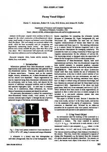
designs that can be parameterized to support custom jewelry designing. The jewelry that confirms to certain repeated patterns can be approached using voxel based technique. In this approach, parametric voxel elements are combined into a jewelry model in a wide variety of possibilities. A large number of jewelry designs can be produced by changing the modeling parameters that refer mostly to the appearance, size and content of the final product. This releases pressure on of the designer to deliver more number of jewelry deigns with even higher numbers of variations. By parameterizing the process; it is very easy to modify characteristics such as the size and shape and hence, produce a variation in the design. The users participate in the designing process through the definitions of the parameters values. This eliminates the formal designer and provides the design tool in the hand of user. The user interactions are directly turned into solid three dimensional models by changing the parameters as he/she can select and modify a voxel set to create a design model and he/she need not to have designing skills. The same design model can be defined and created several times without any change. Users’ requirements can be rapidly customized by reducing the gap which traditionally exists between design and manufacturing i.e. by integrating the design and manufacturing. The designs use a very small structural element said voxel, which is a building block of design model and defined by parameterized geometry and attributes. Users can manipulate the voxel through modeling parameters. With the appropriate definitions of these parameters, a variety of designs models can be created. Voxels are grouped in a voxel set having the same geometrical and dimensional constraints. A voxel set library is created from which the user chooses a voxel set. A design model is created by knowing which voxels are required and in what order they have to be placed. After placing the voxels at their appropriate positions, these are concatenated together to produce a design model. The design model is subtracted from Basic Constructive Solid (BCS) and glued to BCS to produce die and punch model respectively. These three dimensional die and punch models are converted to neutral file format (STL) and transferred to RP machine that quickly translates the three dimensional CAD model into a wax solid object. These wax patterns of die and punch are used to create tools for stretch formed jewelry by lost wax process (Investment Casting). In the present work, generated design models are English alphabets, numbers and special shapes (heart, cross, religious symbols, etc.). The reason for this choice is that the representation of initials, names or special shapes on rings, pendants, bracelets, earrings, etc. gives a personnel touch to the jewelry. The design model may be a word formed by a sequence of alphabets. The system provides the user the ability to rapidly create the jewelry design, based on his/her preferences. Section 2 of the manuscript describes the parametric voxel oriented approach, while the modeling of alphabet designs is discussed in Section 3. Section 4 presents the methodology of creation of forming tools i.e. die and punch. The stretch forming process is elaborated in Section 5. Section 6 discussed implementation of the methodology and finally concluding remarks are presented in Section 7. 2. THE PARAMETRIC VOXEL ORIENTED APPROACH The intention of the approach is to provide sets of parametric voxels elements that are used and changed during the design process. The down stream CAD paradigm is parametric voxel oriented. Voxels are predefined elements for which user define the key parameters. The parameters include geometrical, dimensional and location attributes. Parametric voxels are varied during the design process and are joined together to create the design model by the application of suitable rule(s). The knowledge about design model is treated as set of rules. Design Model (DM) can be viewed as set of voxels (V) and set of rules (R) [2]. The set of rules express the two types of relationships: (i) Relationships between voxel and design model (Rva-DM) (ii) Relationships between voxel and voxel element (Rva1-a2) are illustrated in Fig. 1. These relations are considered as constraints which remain valid even when the voxels are changed. DM = (V, R) (2.1) V= {Va} a = 1, 2, 3...n (2.2) R= (R1, R2) (2.3) R1 = {Rva-DM} a = 1, 2, 3…n (2.4) R2 = {Rva1-a2} a1, a2 = 1, 2, 3…n (2.5) where n is number of voxel elements in a voxel set For alphanumeric design model, eight voxels are defined in a voxel set i.e. n is equal to eight. The relations are unary operations such as transformations (rotation, scaling, mirror, and translations) and binary operations such as union, subtraction, and intersection. Relationships between voxel and design model include: (i) Selection of required type and quantity of voxel elements from a voxel set for a design model (ii) Placement of appropriate voxel element in a two dimensional matrix to create a design model. Relationship between voxel and voxel include attachment of translated voxels.
Computer-Aided Design & Applications, Vol. 4, Nos. 1-4, 2007, pp 137-145
139
Design model level
Design model Voxel Voxel-voxel relationship
Voxel-design model relationship Voxel level
Fig. 1: The parametric voxel oriented approach. 2.1 Description of Voxel Voxel is small structural element that is used as building block to design a model. It is three dimensional solid having specific attributes. Voxels encapsulate how design model behaves using rules in addition to their defining parameters. Designs are modeled by sequence of voxels attachment, which is generative and constraint based process and can reasonably be implemented in CAD system. An alphanumeric design model can be represented by defining and combining different voxels. These voxels are placed side by side, either at top, bottom, right or left of each other, and union into an alphabet design model as shown in Fig. 2. Eight voxels are defined based on aesthetic and artistic knowledge, which can create any alphanumeric design model. These voxels are labeled as V1, V2, V3.....V8 and all these are grouped in a voxel set. Some of voxel sets are shown in Fig. 3. All eight voxel elements have same geometrical and dimensional constraints in a voxel set. To create an alphanumeric design model, voxels to be used must be from one voxel set. Seven numbers of voxels i.e. from V2 to V8 are derived from a voxel V1. V1 is said main voxel and voxels from V2 to V8 are said derivative voxels.
Fig. 2: Alphanumeric design models (Letters M, V, A, and heart). 2.2 Modeling Strategy Voxels are created using the sketching approach which uses 2D entities to sketch a profile or a cross section followed by 3D operations such as extrusion. Some of profiles and main voxel elements created from these profiles are shown in Fig.4 [9].
Computer-Aided Design & Applications, Vol. 4, Nos. 1-4, 2007, pp 137-145
140
Fig. 3: Some of voxel sets. 1. Select a sketch plane: A sketch plane is needed to create profile. The sketch plane controls the orientation of sketched profile in the 3D modeling space. One of the three perpendicular reference planes (XY, XZ and YZ) of the world coordinate system (WCS) may be selected. By default, the profile is created in the XY plane of the WCS is used. 2. Sketch 2D profile: A profile is generated using comprehensive 2D entities like line and arc. The profile is inscribed in a square and created using a set of valid points as shown in Fig 5. The profile is converted into a region and is described using parameters. 3. Extrude 2D profile: The 2D profile/region is extruded to a sufficient depth and taper angle in a Z direction. The extrusion is perpendicular to the sketch plane of the profile.
Fig. 4: Main voxel elements showing maximum number of valid points. 2.3 Modeling Parameters to Create Voxel set A voxel set is described with voxel signature which is a set of modeling parameters and represented as VS-P/L/H/θ/X/Y, where V stands for voxel set, P for maximum number of valid points, L for size, H for height and θ for inclination of side surface of voxel element, X and Y for variants. All of these modeling parameters are illustrated in Fig. 5. 1. No of valid points (P): The maximum numbers of valid points from which these voxels are created may be nine, thirteen, or seventeen. The profile of voxel element is inscribed in a square. The one center and four corner valid points of the square in which voxel element is inscribed are kept fixed. The rest of the valid points are kept variable. 2. Size of voxel (L): It is the size of the voxel element to be created and kept equal to the size of square. The size of voxel is taken proportionate to the size of design model.
Computer-Aided Design & Applications, Vol. 4, Nos. 1-4, 2007, pp 137-145
141
Fig. 5: Representation of nine-point voxel set. 3. Height of voxel (H): It is the height of extruded voxel and equal to depth of extrusion process parallel to Z-axis. This parameter should be such that when metal sheet is stretched with forming tools; it would not be sheared off. The value of voxel height depends upon the percentage elongation of sheet metal used, so it needs to be carefully worked out. 4. Inclination of side surface (θ): This represents taper angle of extrusion process along Z-axis. Voxel sides are tapered to make the side surfaces reflective. Reflective surface send back light giving optical effects. The value of the ‘θ’ needs to be carefully worked out. If the taper angle is too large, the profile terminates to a point before it reaches the specified depth. Moreover, practically in stretch forming process with die and punch, larger taper angle of voxel element will shear off the sheet metal. If the taper angle is too small, side surface of voxel will be not reflective. 5. Variant (X & Y): These are defined as distances between fixed point and next/previous variable point in horizontal and vertical direction. Variants are used to get different profiles of a voxel class. 2.4 Representation of a Voxel Set A voxel set of signature VS-9/10/1/60/2.5/2.5 is shown in Fig.5 and illustrated as follows. This voxel element has nine numbers of valid points i.e. from 0 to 8. Points 2, 4, 6, 8 are variable points and points 0, 1, 3, 5, 7 are fixed points. The Coordinates of valid points are: Point 0 = (L/2, L/2), point 1 = (0, 0), point 2 = (X, Y), point 3 = (L, 0), point 4 = (L-Y, X), point 5 = (L, L), point 6 = (X, L-Y), point 7 = (0, L), point 8 = (Y, X). Variable points 2, 4, 6, 8 can vary between points 0 to a, 0 to b, 0 to c, and 0 to d respectively, where coordinates of point a= (L/2, 0), point b= (L, L/2), point c= (L/2, L) and point d= (0, L/2). Distances 2-a, 4-b, 6-c and 8-d are equal and described as variant Y. Distances 1-2, 2-3, 3-4, 4-5, 5-6, 6-7, 7-8, 8-1 are equal and described as variant X. The value of parameters X and Y in the example is 2.5 units. From aesthetic and artistic knowledge, the relation L/8≤X, Y≤3L/8 should be used as constraints for this class of voxels. Size of voxel element is the distance between points 1-3, 3-5, 5-7, and 7-1 which is equal to size of the square in which this voxel is inscribed shown in Fig.6a. For this example, voxel, size is taken as 10 units. By using these nine valid points, eight profiles (V1 to V8) are created and described in Tab. 1 and shown in Fig. 5. The profile is extruded with parameters depth of extrusion and taper angle which are kept equal to height of voxel element (in example= 1 unit) and inclination of side surface (in the example = 60 degrees) respectively. The value of the ‘θ’ may be taken between 20 to 60 degrees and needs to be carefully worked out. 3. CREATION OF ALPHABET DESIGN MODEL Each alphanumeric design model is a combination of voxels which are placed in a two dimensional matrix of size 5x4 illustrated in Fig. 6, expressing the numbers of rows and numbers of columns respectively. Hence, the size of design model is 5L x 4L. An example of creation of alphabet design model ‘V’ is as follows. Alphabet design model ‘V’ requires two types of voxel elements (8 numbers of V1 and 6 numbers of V3) as shown in Fig. 7. A voxel set is selected and required voxels elements are created. These voxels are transformed in required orientation and then translated to the proper location
Computer-Aided Design & Applications, Vol. 4, Nos. 1-4, 2007, pp 137-145
142
in two dimensional matrix. Each time a voxel element is placed, it is concatenated with the previous ones. For alphabet ‘V’, positions of voxels in two dimensional matrix are shown in Tab. 2. Voxel elements V1 V2 V3 V4 V5 V6 V7 V8
Number and types of primitives used Line=8 Line=5 Line=5 Line=4, Arc=1 Line=8 Line=4 Line=6 Line=2, Arc=1
Valid points used for creating profile 1-2-3-4-5-6-7-8-1 1-2-3-4-0-8-1 1-2-3-4-5-0-1 1-2-3-4-5-1 1-2-3-0-5-6-7-8-1 1-2-7-8-1 1-2-3-6-7-8-1 1-2-8-1
Tab. 1: Description of a voxel set.
Fig. 6: Two dimensional matrix for voxel placement.
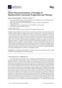
Fig. 7: Alphabet design model ‘V’. 4. CREATION OF FORMING TOOLS: DIE AND PUNCH In this section, stretch forming tools (Die and Punch) models are constructed with two operations, namely, by subtracting volume and by gluing volume respectively. Die models are formed by subtracting from Basic Constructive Solid (BCS) and punch model by gluing alphabet design model BCS as shown in Figure 8. For the purpose, BCS is a rectangular prism having size of 5Lx 4L x D, where, ‘D’ is depth of BCS. The design can be sequence of individual designs. For instance the design may be sequence of alphabets forming a word as shown in Fig. 9. In this case die and punch models of required alphabets or special shapes are joined side by Computer-Aided Design & Applications, Vol. 4, Nos. 1-4, 2007, pp 137-145
143
side to create die and punch design models of the word, but each alphabet and shape should be separated by a gap. So another size of BCS (5L x L x D) is concatenated on the right side of each alphabet die and punch model. Operation Number 1 2 3 4 5 6 7 8 9 10 11 12 13 14
Voxel V1 V1 V1 V3 V3 V1 V3 V3 V1 V3 V3 V1 V1 V1
Matrix Position [1][1] [2][1] [3][1] [4][1] [3][2] [4][2] [5][2] [3][3] [4][3] [5][3] [4][4] [3][4] [2][4] [1][4]
Tab. 2: Description of alphabet design model ‘V’. These 3D punch and die model are converted to STL file, which is the RP defacto standard data transmission format. Present day CAD systems are capable of producing STL files. This STL format is transferred to rapid prototyping machine which slice the CAD die and punch models into thin layers to generate the contours of the models for each layer based on the STL format. Rapid prototyping machine produces wax pattern of die and punch. After cleaning the wax, pattern is invested into a liquid ceramic slurry, and then into extremely fine sand to form a shell. After the shell has dried, the wax is melted out in a high pressure steam autoclave, leaving a hollow cavity in the mold that exactly matches the shape of wax model. Before pouring the casting, the shell is fired in an oven burning out any remaining wax or residue and preparing the mold for the molten metal. Pouring can be done using the conventional gravity method. After the casting has cooled, the ceramic shell is broken off and parts are ready to act [4], [13], [14]. 5. STRETCH FORMING PROCESS Stretch forming produces contoured parts by stretching a metal sheet. The process of stretch forming is method of putting sheet metal under combined bending and tension stresses at the same time. In stretch forming the sheet metal is clamped around at edges and stretch over a die. The process strains the metal beyond the elastic limit to set the metal shape permanently. The punch descends on to the sheet metal to deform the metal into the desired shape by pressing the metal against the die. Stretch forming sheet metal process involves partial or complete plastic deformation of the metal between punch and die and shown in Fig.10. The surface of sheet metal is raised into a pattern of designs. The raised surface is reflected by light imposed on it and gives an effect of visualization of the design to the user. This category can be applied to various types of jewelry such as pendants, rings, earrings and bracelets. 6. IMPLEMENTATION The paradigm is implemented under the Active X and Visual Basic Application programming environment using AutoCAD 04. Autodesk began to support Visual Basic Application (VBA) in the AutoCAD release 14.01. Microsoft VBA is an object-oriented programming environment designed to provide rich development capabilities similar to those of Visual Basic (VB). The main difference between VBA and VB is that VBA runs in the same process space as AutoCAD, providing an intelligent and very fast programming AutoCAD environment. VBA sends messages to AutoCAD by the AutoCAD ActiveX Automation interface. AutoCAD VBA permits the VBA environment to run simultaneously with AutoCAD and provides programmable control of AutoCAD through the ActiveX Automation interface. This coupling of AutoCAD, ActiveX Automation, and VBA provides an extremely powerful interface. AutoCAD is capable of creating STL file, which can be submitted to RP machine, for creating wax model [12].
Computer-Aided Design & Applications, Vol. 4, Nos. 1-4, 2007, pp 137-145
144
‘V’ Die
‘V’ Punch
Fig. 8: Die and punch forming components.
Fig. 9: Die design model of a word.
Die forming tool
Punch forming tool
Sheet metal
Movable grippers
Fig. 10: Stretch forming process. 7. CONCLUSION The paper proposes a new paradigm to create forming components for stretched formed jewelry. Designing of jewelry is a growing area and standardization as well as automation is included through advances in CAD technologies. The work introduces a development in jewelry designing to improve manufacturability and repeatability. The approach has created design models using a parameterized voxels. The usefulness of the approach relies on the use of standard tools
Computer-Aided Design & Applications, Vol. 4, Nos. 1-4, 2007, pp 137-145
145
by CAD system and parameterization of voxels. Computer aided support enhanced a concurrent way of working and capitalized the advantages of computer over hand, especially when it came to more complex design generation. The basic objective is to eliminate formal designer and provide the design tool in the hand of actual users, giving a large number of variations in the designs. By capitalizing the advantages of CAD and RP, this paradigm explains how a pre conceived design intention could be implemented. 8. REFERENCES [1] ArtCAM JewelSmith, http://www.artcamjewelsmith.com, Delcam plc. [2] Au, C. K.; Yuen, M. M. F.: A Semantic Feature Language for Sculptured Object Modeling, Computer Aided Design, 32, 2000, 63-74. [3] Basak, H.; Gulsin, M.: A Feature Based Parametric Design Program and Expert System for Design, Mathematical and Computational Applications, 9(3), 2004, 359-370. [4] Cao, W.; Miyamoto, Y.: Direct Slice from AutoCAD Solid Models for Rapid Prototyping, Advanced Manufacturing Technology, 21, 2003, 739-742. [5] Chau, C. K.; Fai, L. K.: Rapid Prototyping: Principal and Applications in Manufacturing, John Wiley & Sons, Inc., 1997, Singapore. [6] Chau, C. K.; Feng, C.; Lee, C. W.; Ang, G. Q.: Rapid Investment Casting: Direct and Indirect Casting Approaches via Model Maker II, International Journal of Advance Manufacturing Technology, 25, 2005, 26-32. [7] Das, A. K..: CAD and Rapid Prototyping as an Alternative of Conventional Design Studio, International Engineering and Product Design Education conference 2004, Netherlands, 1-7. [8] Fudos, I.: CAD/CAM Methods for Reverse Engineering: A Case Study of Re-engineering Jewelry, ComputerAided Design & Applications, 3(6), 2006, 683-700. [9] Hoffmann, C. M.; Joan-Arinyo R.: On User Defined Features, Computer Aided Design, 30(5), 1998, 321-328. [10] JewelCAD, http://www.jcadcam.com, Jewelry CAD/CAM Ltd. [11] JewelSp[ace, http://www.jewelspace.net, Caligory Software. [12] Mclver, J.: Visual Basic Applications in IntelliCAD, http://www.cadinfo.net. [13] Molinari, L. C.; Megazanni, M. C.: Rapid Prototyping: Application to Gold Jewelry production, Gold Technology, 20, 1996, 10-17. [14] Molinari, L. C.; Megazanni, M. C.: The Role of CAD/CAM in the Modern Jewelry Business, Gold Technology, 23, 1998, 3-7. [15] Stamati, V.; Fudas, I.; Theodoridou, S.; Edipidi, C.; Avramidis, D.: Using Poxels for Reproducing Traditional Byzantine Jewelry, Computer Graphics International 2004, Crete, Greece, June 16-19. [16] Stamati, V.; Fudas, I.: A Parametric Feature Based CAD System for Reproducing Traditional Pierced Jewelry, Computer Aided Design, 4(37), 2005, 431-449. [17] Stamati, V.; Fudas, I.: A Feature-Based CAD Approach to Jewelry Re-engineering, Computer-Aided Design & Applications, 2(1-6), 2005, 1-9. [18] TechGems 3.0, http://www.techjewel.com, TechJewel. [19] Wannarumon, S.; Bohez, E. L. J.: Rapid Prototyping and Tooling Technology in Jewelry CAD, ComputerAided Design & Applications, 1(1-4), 2004, 569-575. [20] Wannarumon, S.; Bohez, E. L. J.: A New Aesthetic Evolutionary Approach for Jewelry Design, ComputerAided Design & Applications, 3(1-4), 2006, 385-394.
Computer-Aided Design & Applications, Vol. 4, Nos. 1-4, 2007, pp 137-145