Proceedings of the 2002 IEEE InternationalConference on Robotics 8 Automation Washington, DC May 2002
A Pragmatic 3D Visual Servoing System T.P.Sim, G.S.Hong and K.B.Lim Department of Mechanical Engineering, National University of Singapore e-mail: engp9
[email protected]
Abstract--This paper presents an attractive positionbased visual sewoing approach for camera-in-hand robotic systems. The major contribution of this work is in devising an elegant and pragmatic approach for 3 0 visual tracking. The proposed Modijied Smith Predictor (MSP)-DeMenthon-Horaud (DH) visual sewoing system has shown to be reliable and yielded good target tracking performance. It d@er from the other techniques found in the vast visual sewoing literature, in ifs approach for image interpretation and the introduction of a Smith-like predictor control structure to overcome the inherent vision delcy. A complete description will be made on the MSP-DH visual sewoing system. Experiments on the target tracking performance on XY planar motion using an AdeptOne robotic system are presented to illustrate the controller pevformance. Also, experimental results clearly showed the capability of the MSP-DH visual servoing system in performing 3D-dynamic visual sewoing.
I.
INTRODUCTION
Visual servoing can be broadly classified in term of feedback representation: image-based and position-based visual servoing; and class of control structure: the dualloop visual servo and the direct visual servo control [I], [2]. Most work on the area of visual servo control has been concentrated on the image-based approach. In this paper the position-based dynamic look and move approach is employ. The method is very intuitive because it allows a direct and natural specification of the desired task in term of 3D pose parameters [lo]. This statement is valid only if we are able to recover the 3D pose parameter from the image data effectively, and efficiently. The primary disadvantages [2] of this method are its sensitivity to camera calibration errors, long computation time requirements, and the need for an accurate geometric model of the target. These are mainly image interpretation problems. The DeMenthon-Horaud (DH) [3], [4], [SI pose estimation algorithm used here attempts to address some of these issues. Approaches taken by Yuan [6], Horaud [7], Wilson [ 101 respectively uses iterative numerical solution, closed form solution, and Extended Kalman Filtering (EKF) technique to obtain the desired pose from a single image. For convergence, the iterative numerical solution requires good initial estimates of the true solution; the close form solution can only be applied to limited number of correspondences; the EKF technique to solve the nonlinear photogrammetric equations is highly complex due to its stochastic nature and requires proper selection of the noise covariance matrix. In contrast, the DH algorithm is an elegant and simplistic pose estimation 0-7803-7272-7102/$17.00 0 2002 IEEE
algorithm, which enables effective and quick computation of pose estimates. The algorithm has the accuracy and robustness to make 3D visual servoing possible as will be presented in this paper. The availability of full pose information make it possible to independently design the dual-loop visual servo controller without added interaction from the vision system. Furthermore, it is well known that the dynamic look-and-move approach is pragmatic and enables established encoder-based position servo to stabilize the robotic manipulator. In the framework of position-based dynamic look-and-move system, we proposed the use of the Modified Smith Predictor 1141 (MSP) control structure to address the multi-rate and time delayed nature [8], [9] of the visual servo control scheme. Previous approach for a dual-loop visual servo control system takes the form of a dosing visual feedback loop using predicted values of positioning information [101, [111. The approach taken here differs from these previous approaches by the incorporating the control prediction within the control structure. It applied well-researched predictor control scheme to maintain robustness of the visual control system in the presence of high vision delay. Analytical, simulation and experimental studies [141 have shown the effectiveness of the MSP visual servo controller to amve at the required performance characteristics for good target tracking. The use of Smithlike predictor control scheme for visual servo control is not new, and has been investigated by Brown [12], and Sharkey [13]. Both have come to the same conclusion; the visual servoing performance improves with the use of a Smith-like predictor control scheme. However their works did not include implementation of such a control scheme for allowing a robot to exploit its environment. In our case, the robot needs to move and fixate on a dynamically unknown moving object. In this paper, we demonstrated the feasibility of implementing the MSP-DH visual servoing system. We have successhlly implemented this algorithm to perform 3D dynamic visual tracking. Section 11 formulates the necessary algorithms for the MSP-DH visual servoing system. To infer 2D image data to 3D pose parameter, the DeMenthon-Horaud pose estimation algorithm is given. These pose estimates are then successhlly incorporated into the Modified Smith Predictor control structure to handle the inherent multi-rate time delayed nature of the visual servo control system. Section 111 presents the experimental results for target tracking performance and 3D visual tracking using an AdeptOne robotic system and a transputer based vision system. Lastly section IV gives the conclusion to this paper.
4185
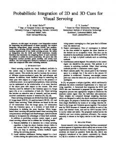
and pi give the corresponding image points in the retinal plane {R} for the fixation point and feature points respectively. The vector ''t represent the position of the fixation point with respect to the camera coordinate frame {C'}. d is the optical distance from the focal point to the retinal plane. From classical perspective modeling, we can obtain the following equations:
11. MSP-DH VISUALSERVOING SYSTEM The principal benefit of the position-based approach is the decoupling of the image interpretation and the visual servo controller. In this paper, we proposed the use of the DeMenthon-Horaud (DH) pose estimation algorithm for pose recovery from the 2D image data. The Modified Smith Predictor (MSP) control scheme is designed based on the availability of the estimated pose vector.
-+
ix(1+ & i ) = I.P0Pi+xo
(1)
-+
A. Pose Estimation Algorithm The DH pose estimation algorithm establishes a link between linear scaled orthographic projection with nonlinear techniques of perspective modeling. The original method by DeMenthon and Davies [3] involved the use of weak perspective transformation. However it has difficulty in achieving fast convergence when the object center point is located away from the optical axis. Horaud [4] proposed an extension to this method by using para perspective approximation. This method improves the approximation of object located at some distance from the optical axis and also results in better convergence rate. In this paper we assumed the tracking object to be a 3D non-coplanar object with features points that are readily detectable.
iy(l+~i)=J.IPoPi+yo (2) where I = i.d I t, ;J = j.d I t, , xo = tx/tz ;yo = t,/t, and -)
si = k.PoPi/t, Equations (1) and ( 2 ) are clearly non-linear. Hence, this makes the inverse imaging problem to be non-trivial and computationally prohibitive for visual servoing. We therefore opted for a linear pose estimation method by implicitly uses the Scaled Orthographic Projections (SOP) of the feature points to solve this problem. The SOP used here is known as para perspective. In para perspective camera model, we take the first order approximation of perspective i.e. 1 -= 1-8~ Vi,iE {1,2 n} (3) 1+&i From (1) and (2), this result in the following para perspective projection equations
,...,
-+
lxp =np.P,Pi+xo
(4)
-+
'
~
e*. X
Fig. 1. Pinhole camera model
A simple pinhole camera model is used in depicting the mapping of the 3D object feature points to the retinal plane (R}, as illustrated on Fig. 1. Here the object feature points are denoted by 'Pi (Xi, Yi, 2;) where i={0,1,2,..N: N23). Po gives the origin of the object coordinate frame (0). We call Po the object fixation point. The feature points, 'Pi are defined with respect to the (0)coordinate
(5)
pJp.PoPi+Yo
di-x, k
dj-y, k
where I, = -and J, =t, t, The DH pose estimation method make use of the para perspective approximation to iteratively converge to that of a full perspective transformation thus giving us a good estimate of position and orientation of the target of interest. Hence, a link must be established between the perspective equation of (1) and ( 2 ) and that of the para perspective equation of (4) and (5). The iterative pose estimation algorithm is described by the following pseudocode [4][5], 1. For all i = {0,1,2, ...., N},N 13, e = 0 2. Loop begins. Solve the for I, and Jp using the following over constrained linear system derived from (1) and (2): -+
(i x- xo)(l + Ei ) = I,. POPi
(6)
-+
y- yo)(l+ ~ j =) J, .POP, (7) With non-coplanar object points, object matrix (I
-+
frame and are represented by the vector quantity POPi.po
4186
2. In the limited bound for visual servoing, actual experimental results show a mean error of 0.32" for X-axis and 0.65" for Z-axis. The selection is to illustrate the sharp contrast in measurement errors between two groups of movements. Movement in X , Y, direction results in bigger changes in the image plane. Thus they are more sensitive compare to movement in Z, 8 and y direction where small changes in image plane are expected. Hence the pose estimates for movement in 5 Band ydirections are noisier and require some form of conditioning.
i
POPihaving full rank and the solution of I, and J, can be accomplished by the pseudo-inverse of -+ POPi. The solution will gives an estimation of vectors I, and J,. 3. Compute for scaling factor tz and k
then, t, =-,X O t , and t , =& d d From definition of I, and Jp , t,I,+x,k t , J p +YOk 1= ,and j = hence d d
B. MSP Visual Servo Controller Lets denote T as the 4x4 homogenous transformation matrix and s(.) is a function decomposing T to the corresponding 6 parameters. Fig. 2 shows the required coordinate frame assignment to formulate the required error vector, consistent with the MSP control scheme. The reference coordinate frame, {Cref) is the desired pose to be achieved by the arm to maintain visual fixation. Hence, the control objective is to ensure:
.
k =ixj=(d21,,,-t,Skb,)+t,Sk(J,))-'(t,I, x J , ) (9) where SNIP)and Sk(J,) is the skew-symmetric matrix of I, and Jprespectively. 4. For homogeneous transformation matrix
' :,
(12)
To achieve this within the framework of the MSP visual servo controller, the control system must exhibit good disturbance rejection capabilities. Differing from the standard Smith Predictor control scheme, the MSP control scheme has good disturbance rejection characteristics [9].
5. Compute for all i, +
6.
('To(t)-Cre'To(t))=O
I f Isi( t ) - si(t - 11 e Threshold, Exit
Else t = t+l. Loop to step 2. 7. Pose estimation = last approximate pose, To This algorithm makes it possible to estimate the pose of a 3D non-coplanar object from the image it projects on the camera at every time period of 20ms. Application of DH pose estimation algorithm in visual servoing is influenced by the camera to object distance/object's size ratio, the corruption of image noise and the mismatch in calibrated parameters. The calibrated parameters include the image plane to focal point distance, the scaling factors, the image plane principal point and the object geometric model. These factors influence the accuracy and stability of the algorithm in arriving at the required pose estimates. Base of extensive simulation and experimental results conducted on the DH pose estimation algorithm, in the limited bound of object's pose changes during visual servoing, we can conclude the followings; 1. To maintain good pose estimates and ensure stability of the iterative DH pose estimation algorithm, the distancehize ratio of 8-1 5 should be selected. Fig. 2. Pose vector relationship
4187
Visual Servo Control
I
I
I
I
I
Fig. 3. The MSP Visual Servo control structure
Fig. 3 illustrates the control block diagram of the MSP visual servo control structure. G, GA denotes the actual and modeled AdeptOne robotic systems. Therefore both are considered stable systems. K denotes the digital controller designed to produce the required stability and performance characteristics for a unity, negative output feedback configuration of GA.The visual servo system is regarded as a series connection of a robot manipulator with a visual capturing system. The robot manipulator is represented by a convolution subplant G with unirate sampling interval of T,. The visual capturing system is represented by the sampling operator S which selects every N-th output from G to generate the measured output samples, and a delay operator D represent the delay time involved in the image processing task. The notation r, d and U represent the reference, disturbance and control signal respectively. yN and yNA are the measured and predicted output respectively. As with any Smith Predictor control scheme, the main aim of such a control scheme is to take the delay outside the feedback loop thereby allowing the controller to be tuned on a basis of an equivalent system without any delays. From Fig. 3, the MSP control structure consists of a simple predictor, F that is placed in the major feedback of the standard Smith Predictor control scheme. By having an approximate inverse delay, we are able to forecast the delayed vision measurement values one delay time into the future. This in turn eliminates the delay time between the dynamic of the observed target, d and the control, U in a similar fashion to the feed forward Smith predictor. However to achieve this, several conditions need to be fulfilled. The MSP control structure maintain good target tracking characteristics and robustness if; C1: The controller gain, IKI must be suficiently high C2: The predictive filter, F should accurately predict the future values one unit time step ahead. C3: The modeling error, (G-GA)need to be small Conditions C1, C2, and C3 ensure good target tracking characteristics of the MSP visual servo controller [14]. In addition, condition C3 is vital to ensure robustness of the overall control structure [8]. In actual implementation, to approximate the requirements of C1, a PID controller is
Fimtimf Goal
(B