Functional Duplex March Testing of Word-Oriented Multiport Static RAMs. Kanad Chakraborty. Pinaki Mazumder. Department of EECS. Department of EECS.
A Programmable Boundary Scan Technique for Board-level, Parallel Functional Duplex March Testing of Word-Oriented Multiport Static RAMs Kanad Chakraborty
Pinaki Mazumder
Department of EECS The University of Michigan Ann Arbor, MI 48109
Department of EECS The University of Michigan Ann Arbor, MI 48109
Abstract A framework for integrating boundary scan (IEEE 1149.1) with board-level self-testing of word-oriented, multiport static RAM chips is proposed. Innovative parallel versions of functional duplex march tests (FDMs) for detecting complex couplings are developed. This approach produces significantly smaller cycle-time penalty during normal operation than built-in self-testing (BIST). It produces two orders of magnitude test acceleration as compared to pure boundary scan testing without BIST (i.e., by using EXTEST and SAMPLE/PRELOAD instructions only). Key words and phrases: Boundary scan, bus interface unit, march tests, functional duplex march algorithms (FDM)
1
Introduction
Multiport static RAMs are used widely nowadays as application-specific memory ICs to reconcile speed mismatch between a processor and a peripheral device, or as message passing buffers among distributed processors. Although they are better equipped to meet the challenges of high-performance systems such as multimedia and highspeed networks, testing these chips at the board-level is associated with several problems, as follows: (a) internal circuitry of multiport RAMs is more complex and expensive, and incorporating (on-chip) BIST would lead to higher system cost and unacceptable timing overhead; (b) having boundary scan circuitry within a multiport RAM chip is infeasible, because it would double or even triple the size and cost of the device and add delays to the circuit; (c) simultaneous write capability of multiport RAMs leads to new fault types, such as complex coupling faults [3, 4] hence new types of tests are necessary;
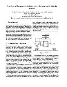
(d) for comprehensive fault coverage, both ports have to be simultaneously enabled during test mode, and this requires dual pattern generation and dual timing arrangement, which are difficult and costly with existing memory testers. This paper presents a practical and efficient board-level self-test approach for minimizing or eliminating all of the above problems. Figure 1 shows a simplified schematic of a typical microprocessor board with boundary scan [1]. Instead of providing built-in (i.e. on-chip) self-testing (BIST) for the embedded RAMs and the glue logic, a useful approach, originally proposed at Texas Instruments [5] is to incorporate test circuits within the external bus-interface unit (BIU) driving the address, data and control pins of the memory devices. This is done by programming the IEEE 1149.1-compliant bus interface buffer or transceiver using boundary-scan instructions, into a test pattern generator (such as a binary counter or a linear feedback shift register (LFSR)) or as a signature analyzer (such as a parallel signature analyzer (PSA)), under control of the test bus. Sometimes, the same device may be reconfigured into LFSR and PSA at different times during the self-test. For example, in order to test the glue logic, the buffers A and B may be reconfigured into LFSR (also called pseudorandom pattern generation or PRPG) mode, while the buffers C and D are reconfigured into PSA mode; to test the embedded memory, the buffers C and D may be placed in LFSR mode, while the buffer E is placed in PSA mode. In this paper, a self-test architecture and corresponding parallel self-testing algorithms using similar bus interface devices have been proposed for multiport SRAM chips. The ScopeTM family of scan test devices [5] is a good example of commercial bus-interface devices of this nature. The algorithms proposed are parallel versions of the functional duplex march algorithms (FDMs) proposed by Nicolaidis, et al. [4]. The fault coverage achieved by these parallel tests can be proved to be as high as their sequential coun-
ED&TC ’97 on CD-ROM Permission to make digital/hard copy of part or all of this work for personal or classroom use is granted without fee provided that copies are not made or distributed for fee or commercial advantage, the copyright notice, the title of the publication, and its date appear, and notice is given that copying is by permission of the ACM, Inc. To copy otherwise, to republish, to post on servers, or to redistribute to lists, requires prior specific permission and/or a fee. 1997 ACM/0-89791-849-5/97/0003/$3.50
C
A
EMBEDDED PROCESSOR
EMBEDDED MEMORY
GLUE LOGIC D
B
1. Define the ‘forward’ addressing sequence as concatenation of the following subsequences (note C1 , C2 , etc. denote the memory words):
� � �
Subseq1: hC1 ; C2 i; hC1 ; C3 i; : : : hC1 ; Cn i
Subseq2: hC2 ; C3 i; hC2 ; C4 i; : : : hC2 ; Cn i : : : Subseq(n-1):hCn 1; Cn i
BUS INTERFACE DEVICES
and the ‘backward’ addressing sequence as the reverse of the above. E F G
TAP CONTROLLER PAL
TDI TMS TCK TDO
Figure 1: Printed circuit board with IEEE 1149.1 test chips; to test the glue logic block, A and B must be in PRPG mode, whereas C and D must be in PSA mode; to test the memory block, C and D have to be in PRPG whereas E has to be in PSA mode; to test both glue logic and memory simultaneously, C and D must be reconfigured to combined PSA/PRPG mode terparts.
2
2. Decompose each multi-operation march element into an ordered sequence of single-operation march elements. For example, the march element * (R00 ; D11 ; D00 ; S10 ; S20 ) [4] is decomposed into * (R00 ), * (D11 ), * (D00 ), * (S1 ), * (S2 ): This decomposed version is called the ‘single-op’ marching version, the 0 0 original version being described as ‘multi-op’. test 3. Insert a dual (single)-port write operation, Dtest i j (Si ), (with i; j 2f0; 1g), that would be executed using the two extra (arbitrarily chosen one) write-only test ports after every dual (single)-port write operation, W, so as to invert the data in location Ci when the march takes place through Subseqi. Also, every read operation, R, is paired up with the immediately preceding write operation, such that the read address refers to the next pair of locations in the march sequence. This read (R) as well as the dual-port (or single-port) test write Dtest ij (or Stest i ) operations march through the memory with a lag of half a TCK cycle behind the W march. For each march sequence Sk , an extra copy of the dual-port read operation that starts the sequence is inserted after the last write operation, Wk;last , and is marched through the memory with a lag of half a TCK cycle from the Wk;last march. 4. Successive write marches (for example, * (D11 ), * (D00 )), taken from the original version of the algorithm are executed sequentially. 5. No-ops in the original test are removed and replaced by dual port write operations, overlapped with leading read operations of march sequences, so as to achieve the same effect.
Figure 2: Procedure for parallelizing a multiport march test
Parallel functional duplex march (FDM) algorithms
The parallelizing technique developed in this paper can be used with any multiport march test, and requires the availability of P read-only ports and two write-only ports, where P is dependent on the march test. For tests FDM1 and FDM2 in [4], P = 2 and 4, respectively. A large number of multiport memories used today have multiple readonly and write-only ports, so this assumption is not a serious limitation of this technique. The steps to parallelize the FDM algorithms are shown in Figure 2. A similar technique can also be used to parallelize any other multi-port march test). (We suggest that the reader has a copy of [4] handy to understand our scheme.) The procedure in Figure 2 produces the following parallel, single-op versions for the multi-op tests FDM1 and FDM2, known as PAR FDM1 and PAR FDM2, respectively, with operations that can be done in parallel (i.e. with only a 1/2 TCK phase lag) parenthesized. The wordoriented versions of these tests would consist of multiple background patterns, depending on the degree of columnmultiplexing of the RAM. These procedures are shown in Figure 3. Theorem: Assuming that reads and non-transition writes are fault-free, the test PAR FDMi (i=1,2) has the same fault coverage as FDMi test (i=1,2). Proof: Corresponding to every read operation in FDMi, PAR FDMi has, by construction, a read operation that is preceded by the same sequence of write transitions. Also,
In the following algorithms, each * or + refers to the concatenated addressing sequence:
� PAR FDM1: test test test Init&S1: * (D00 ; Dtest 11 ; R00 ), * (D11 ; D00 ), * (D00 ; D11 ),* (D11 ; D00 ), * 2 test (S10 ; Stest 1 ), * (S0 ; S1 ; R00 ) test test S2: * (D11 ; Dtest 00 ; R11 ), * (D00 ; D00 ), * (D11 ; D00 ; R11 ) test test 1 test 2 test S3:+ (D00 ; Dtest 11 ),+ (D11 ; D00 ), + (D00 ; D11 ),+ (S1 ; S0 ), + (S1 ; S0 ; R11 ) test test S4: + (D00 ; Dtest 11 ; R00 ), + (D11 ; D00 ),+ (D00 ; D11 ; R00 ) test test 1 test S1’:* (S11 ; Stest 0 ),* (D01 ; D10 ), * (D10 ; D01 ), * (S0 ; S1 ; R00 ) S2’:* (D11 ; Dtest * (S20 ; Stest * (D01 ; Dtest 00 ; R11 ), 1 ), 10 ), 2 test * (D10 ; Dtest 01 ),* (S1 ; D0 ; R11 ) test test 2 test S3’: + (S11 ; Stest 0 ),+ (D01 ; D10 ),+ (D10 ; D01 ), + (S1 ; S0 ; R11 ) 1 test test S4’:+ (D00 ; Dtest ; R00 ), + ( S ;S ) , + ( D ;D + (D10 ; Dtest 01 11 0 1 10 ), 01 ), + (S10 ; Stest 1 ; R00 ) � PAR FDM2: test test test Init&S1: * (D00 ; Dtest 11 ; R00 ), * (D11 ; D00 ), * (D00 ; D11 ),* (D11 ; D00 ), * 2 test (S10 ; Stest 1 ), * (S0 ; S1 ; R00 ) test test S2: * (D11 ; Dtest 00 ; R11 ), * (D00 ; D11 ; R00 ), * (D11 ; D00 ; R11 ; R11 ) test test 1 test 2 test S3:+ (D00 ; Dtest 11 ),+ (D11 ; D00 ), + (D00 ; D11 ),+ (S1 ; S0 ), + (S1 ; S0 ; R11 ) test test S4: + (D00 ; Dtest 11 ; R00 ), + (D11 ; D00 ),+ (D00 ; D11 ; R00 ) test test 1 test S1’:* (S11 ; Stest 0 ),* (D01 ; D10 ), * (D10 ; D01 ), * (S0 ; S1 ; R00 ) 2 ; Stest ; R ), S2’:* (D11 ; Dtest ; R11 ), * ( S * (D01 ; Dtest 10 00 0 1 10 ; R01 ), 2 test * (D10 ; Dtest 01 ; R10 ),* (S1 ; S0 ; R11 ) test test 2 test S3’: + (S11 ; Stest 0 ), + (D01 ; D10 ),+ (D10 ; D01 ), + (S1 ; S0 ; R11 ) 1 test S4’:+ (D00 ; Dtest ; R ) , + ( S ; S ) , + ( D ; Dtest + (D10 ; Dtest 00 01 11 0 1 10 ), 01 ), + (S10 ; Stest ; R00 ) 1
Figure 3: PAR FDM1 and PAR FDM2
each no-op in FDMi is essentially replaced by a pair of opposite write transitions, that cancel each other. 2 By counting the number of test clock (TCK) cycles, PAR FDM1 is seen to achieve a speedup of 1.114 (or, 39/35) over the sequential FDM1 algorithm, and PAR FDM2 is seen to achieve a speedup of 1.257 (or, 44/35) over the sequential FDM2 algorithm. Note that for PAR FDM2, sequence S2 is the ‘bottleneck’ sequence. Since the march element in the multi-op version of S2 (i.e., the original FDM2 algorithm [4]) begins and ends with read operations, sequence S2 forces the use of four read ports simultaneously instead of two (two for reading the current pair of addresses, two for the next pair). For the other sequences, two read ports would suffice.
3
nally controlled by the ATE system running boundary scan), and pseudorandom patterns (successive count patterns) are generated by the device in PRPG (BINARY COUNT) mode. 2. The bus-interface device can go into BYPASS mode by simply scanning in the IEEE-1149.1 normal BYPASS instruction, and then scanning ‘0’ through the single-bit BYP. 3. The scan sequence in PSA mode is analogous to that in PRPG mode; however, after the TAP has entered the Runtest/Idle state, the device starts compressing response patterns for as many TCK pulses as desired. Hence, the PSA mode can be used only with the data buffers in the memory, not the address buffers, since addresses are always input to the memory.
The test architecture
The above modification of march tests makes it conducive to use them for testing multiport RAMs in a reconfigurable boundary-scan based testing paradigm involving the use of discrete test devices that are designed to meet JTAG specifications [2]. Such a device can be programmed to one of three modes: (a) ‘counting’ mode (such as binary counting and pseudorandom pattern generation (PRPG) [5]); (b) ‘bypass’ mode, in which it ignores the boundary scan test clock TCK and retains its contents; and (c) ‘signature analysis’ mode, such as a PSA (parallel signature analyzer). Combined modes are also possible, in which one port of a bus-interface device can be programmed to be in pattern generation mode (such as PRPG or BINARY COUNT), and the other to be in response verification mode (such as PSA). A few of these modes are described below. In the following description, TAP controller denotes the test access port controller of the device with JTAG (IEEE 1149.1), IR denotes the instruction register of the device; BSR, its boundary scan data register; BCR denotes the boundary control register; BYP denotes the bypass register, and DIR denotes a control register that sets the direction of counting to ‘up’ or ‘down’. The instruction and data register scans are also known as IR and DR scans. 1. To enter into PRPG (or BINARY COUNT) mode, the IR of the bus-interface device scans in an instruction that causes the BCR to be selected in the scan path between TDI and TDO (test data in and out pins). This is followed by scanning in a small, usually 2-3 bit code for PRPG (or BINARY COUNT) into the BCR. For BINARY COUNT mode, the DIR is set after this, but for PRPG, this is not required. This is followed by another IR scan that causes an instruction for running the self-test to be set up in the IR. Next, a DR scan allows the initial seed to be set up in the BSR. The TAP then enters the Runtest/Idle state for as many TCK cycles as desired (the number of TCKs is exter-
4
Test program design for PAR FDM1 and PAR FDM2 algorithms
Since PAR FDM1 and PAR FDM2 tests consist entirely of only ordered pairs or ordered triplets of (single- and dualport) write and read marches, it suffices to describe the manner of programming each of these types of march elements into the bus-interface unit. We assume that each k-bit address buffer (for instance, k = 8) can be programmed to be in BINARY COUNT mode and each k-bit data buffer can be set to either a BINARY COUNT mode (for data background generation) or a PSA mode (for response compression). Of course, any address or data buffer can be set to BYPASS mode also. The address and data lines may be partitioned among these bus interface devices; but for simplicity, we shall assume that each address buffer is wide enough to generate the entire range of memory addresses in BINARY COUNT mode.
*
1. A march element involving an ordered pair, for example, (D11 ; Dtest 00 ) of single- or dual-port read/write operations, causes a forward (or reverse) addressing sequence to be applied through one port of the memory. These ordered pairs of addresses may be generated by setting one address buffer to BINARY COUNT mode and the other to BYPASS mode, to allow it to hold its contents. The test write data can be held steady during one complete (forward or backward) march cycle by scanning a seed pattern into the data buffers and setting these buffers to BYPASS mode throughout the marching sequence. The test test write marches, such as Dtest i j and Si , lag half a TCK cycle behind the regular write marches (i.e., Dtest 00 in the above example lags half a TCK behind D11 ).
*
2. For a march element involving an ordered triplet, for example, (D11 ; Dtest 00 ; R11 ); the data buffers for the
BUFFER
M ADDRESS
BUFFER
ADDRESS
L DATA BUFFER
DATA BUFFER
ADDRESS
BUFFER
DATA BUFFER
ADDRESS
DATA BUFFER
K
J
H
G
BUFFER
F
E
Data Bus
2
A
2 Write Only Ports
EMBEDDED DATA BUFFER
PROCESSOR
Read Only Ports
B
Read
ADDRESS
Read / Write
BUFFER
Strobe
C
Clock
and/or
MULTIPORT RAM
DATA BUFFER
Write Ports
Address Bus
*
Table 1: Boundary scan micro-operations for the march sequence (D00 ; Dtest 11 ; R00 )
ADDRESS BUFFER
D
Type of Scan IR DR IR
COMBINATIONAL
A
LOGIC TCK TMS Memtest
BUFFER
Runtest
B
Test_CS
(for buffering test control signals)
Read B.S.R.
T.P. Bypass
IR
0 Embedded Processor Reset
TAP State Variables
TAP CONTROLLER PAL
R/W
I
KEY Bus Interface Devices that are equipped with IEEE 1149.1
Figure 4: A RAM with at least 2 read-only and 2 writeonly ports (note: bus interface devices equipped with IEEE 1149.1 have been labeled A through M)
Bus-Interface Devices
Strobe
Key
DR IR
C
D
E
Read
C
B.S.R.
Read B.S.R.
Read
2
T.P. Bypass
0
C
0
1
B.S.R.
Read
Scan Count B.C.R. Code
Bypass
Runtest/ Idle State for n TCKs B.S.R. Boundary Scan Data Register B.C.R. Boundary Scan Control Register
Runtest
T.P.
B.S.R.
Scan PSA B.C.R. Code
T.P. Test Pattern C
F
Read
1
Scan Count B.C.R. Code
T.P.
Scan PSA B.C.R. Code
C3
Bypass 0
C
B.S.R.
,C ,C 1 2 3 Successive word addresses in the memory Read
read operation are programmed to be in PSA mode, and both reads and test writes lag half a TCK after the regular writes. The address buffers are programmed as above. Figure 4 and Table 1 illustrate the above method with an example, for a multiport RAM executing the march element (D00 ; Dtest 11 ; R00 ): In Table 1, T.P. refers to the background data pattern corresponding to the test pattern ‘0’, and T.P. refers to its bit-wise complement. The boundary-scan instructions used in Table 1 are similar to those for the Scope OctalsTM and 18-bit devices described in [5].
*
5
Results
5.1 Fault coverage As explained before, any multi-op march test for multiport RAMs can be easily parallelized into a single-op march test that has the same fault coverage as the original test, provided the required number of read-only and write ports are present. For a large range of practical multiport memories, especially those used in telecommunication ASICs, this requirement is met. In particular, PAR FDM1 and PAR FDM2 have the same fault coverage as FDM1 and FDM2 [3, 4]. Therefore, these parallel algorithms
G
H
I
J
Read B.S.R.
Read B.S.R.
Read MemBypass B.S.R. Test =1
Read T.P. Bypass
0
B.S.R. IR
Extest
0
B.S.R.
K
Read
C
B.S.R.
2
Scan Count B.C.R. Code Runtest
L
M
Read B.S.R.
Read B.S.R.
T.P. Bypass
0
C
0
1
Bypass
Instruction Reg.
DR Data Reg.
5.2 Test application time compared to alternative approaches Boundary-scan can also be used in a somewhat different manner for RAM self-test; namely, to send an enable input to the BIST circuitry with the help of a special instruction register (IR) operation called RUNBIST, and then set the TAP controller to Runtest/Idle state until the test has completed. This method assumes that the RAM under test already has on-chip test circuits. Use of on-chip test logic will cause faster test application than any of the competing approaches, and is slightly better than our approach in this regard (because it avoids some of the scanning overhead), but suffers from two main disadvantages: (a) potentially low and inflexible fault coverage, and (b) delay penalty during normal mode. BIST automates the execution of a specific memory test algorithm which may not have a high fault coverage for all types of multiport RAMs and cannot typically be generalized, unless the test is microprogrammed (causing higher silicon area overhead) into an EEPROM or some other non-volatile memory. Moreover, the use of BIST circuits will cause a greater delay penalty in the RAM than the present approach, explained shortly. Alternatively, the pure boundary scan approach would use EXTEST/SAMPLE scans for scanning in each test pattern and scanning out each response pattern. This method is extremely slow. For 64 K RAM words ranging from 8 to 256 bits per word, the speedup is experimentally found to range from 229 (with 8-bit bus-interface parts) to a maximum value of 2548 (with 18-bit parts); this assumes an 8-bit IR (instruction register) and a 4-bit BCR (boundary control register) for the bus-interface parts.
5.3 Impact on the RAM access time The bus-interface devices equipped with the RAM test circuitry are built using BiCMOS technology that is considerably faster than pure CMOS. From this perspective, the impact on access time during normal mode is less than with on-chip BIST which would be built using CMOS. On the contrary, if on-chip BIST is built using a hybrid bipolar/CMOS technology, it would cause a sharp increase in the processing cost.
6
Concluding remarks
An important advantage of this scheme for board-level self-testing is its versatility. A wide range of commercial ASICs and off-the-shelf ICs, including multiport RAMs,
Speedup achieved by programmable self-test modes over EXTEST/SAMPLE 3000 8-bit 18-bit 36-bit 2500
2000
Speedup
cover all single and multiple noninverting duplex coupling faults, stuck-at faults (with dominant or non-dominant effect), noninverting simplex coupling faults, and concurrent coupling faults, under the restrictions that opposite transitions on a memory word C j do not have the same effect on another word Ck , and both C1 and Cn do not simultaneously affect Ck .
1500
1000
500
0 0.8
1
1.2
1.4 1.6 1.8 2 Log (base-10) word size of multiport RAM
2.2
2.4
2.6
Figure 5: Speedup per word read or write achievable with 8-bit, 18-bit and 36-bit programmable bus-interface parts for a 64 K RAM with word size varying from 8 bits to 256 bits do not have any built-in self-test but may often require some fairly standard test hardware, such as binary up/down counters. Integrating these hardware with bus-interface devices would result in improved test access at low cost. This work is the first attempt at proposing a boundary scan-based design for testability approach for multiport RAMs, that avoids some of the disadvantages of both on-chip BIST and board-level boundary scan.
References [1] Abramovici, M, Breuer, M.A., and Friedman, A.D., “Digital Systems Testing and Testable Design,”IEEE Computer Science Press, 1995. [2] IEEE Standard 1149.1-1990, IEEE Standard Test Access Port and Boundary Scan Architecture, IEEE Standards Board, 345 East 47th Street, New York, NY 10017, May 1989. [3] Castro Alves, V., et al., “Built-in Self-Test for Multiport RAMs,”Proc. IEEE International Conference on Computer-Aided Design, (ICCAD), Santa Clara, USA, November 1991, pp. 248-251. [4] Nicolaidis, M., et al., “Testing Complex Couplings in Multiport Memories,” IEEE Trans. on Very Large Scale Integration (VLSI) Systems, vol. 3, no. 1, March 1995, pp. 59-71. [5] Texas Instruments, “Boundary-Scan Logic IEEE Std. 1149.1 (JTAG): 5 V and 3.3 V Bus-Interface and Scan Support Products,” Data Book, Advanced System Logic Products, Texas Instruments, c 1994.