A Reverse Engineering Approach to Evaluate Function Point Rules A.April 1, E.Merlo 2, A.Abran 3 1 - Bell Sygma, 1000 DeLaGauchetière Ouest, Montréal, Québec, Canada ,
[email protected] 2 - DGEGI, Département de Génie Informatique, École Polytechnique C.P. 6079, Succ. Centre Ville, Montréal, Québec, Canada,
[email protected] 3- Département d’informatique, Université du Québec à Montréal, C.P. 8888, Succ. Centre Ville, Montréal, Québec, Canada,
[email protected]
Abstract Function Points are generally used for measuring software functional size from a user perspective. This paper is concerned with the problem of counting function points from source code using the Function Point Analysis proposed by the International Function point User Group (IFPUG) 1994 standards. This paper
presents the Automated FP counting scope and objective, the presentation of an existing semi-formal model and the required extensions for the definition of four IFPUG rules. Then we propose reverse engineering techniques to address those four rule.
Keywords: Automation of Function Point, Reverse Engineering, Software Measurement, backfiring. used to build a software, has become an important measure of
1. Introduction Function point analysis (FPA) is the measurement of the functional size of software. The function point (FP) method initially developed by A.Albrecht [2] was conceived to calculate the function value delivered to user. The function point was then used as an input to a model for measuring application development productivity. FPA has evolved since 1984 via the CPM (Counting Practices Manual) published by the IFPUG (International Function Point Users Group). The current version number, as of January 1994, is version 4 [8]. The CPM provides a method with a set of rules for measuring functionality from the users point of view. Function points is a unique software measure in the sense that its evolution, supporting documentation and international certification process for IFPUG counters has considerably augmented the counting precision from 1970 to 1990 [11] [14] [21]. The FP measure, being independent of the type of source code
functional size of a software [12]. Functional size is then used in conjunction with other measures for determining economic productivity, estimation studies and quality evaluations of software applications. FPA is gaining wide acceptance in commercial environments [7]. Bell Canada is using the FPA as prescribed by the IFPUG standard as well as the ‘backfiring’ technique proposed by Jones [13]. The ‘backfiring’ technique is a simple approximation model. The input to the approximation technique is the programming language type and the number of lines of codes of an application. The output is an estimated number of FP’s. Although practical the reliability ranges of this technique is not known and its experimental context from which it was derived are not documented which makes it very perplexing within the field of measurement and measurement instrumentation. This technique does not
1
take into account any of the IFPUG standard counting rules. There would be a benefit in developing techniques, that can be easily automated, that would take into account the CPM counting practices concepts, rules and procedures. The benefits would be to support the manual counts and automatically count the existing and implemented applications with the same reference model used earlier in the life-cycle. The FP’s use, in our company, is mainly used as an input to the estimation model of software development systems. Other potential use for Bell Canada is obtaining CPM function points for its existing applications for productivity benchmarking studies. The following table highlights other intended use of the function points when other important measures (i.e. effort and defects are used in conjunction with FP’s.)
reverse engineering techniques to address those four rules, we present a discussion on precision and how to assess the IFPUG rules during source code analysis. Finally we present our conclusions and future work.
2. Automatic FP counting 2.1 Scope and objectives The latest version of the definition of several concepts of functional size measurement is presented in an ISO/IEC/WG10 draft international standard currently under review [10] which presents the following terminology that will be used internationally when referring to the measurement of the functional size of a software system. Functional size (FS) is the size of the software derived by quantifying the functional user requirements [10]. A functional size measurement (FSM) is the process of measuring functional size [10]. A functional size measurement method (FSM Method) is a specific implementation of FSM defined by a set of rules. Function Points Analysis is an FSM Method. Automatic FP counting relates to the automation of the FSM Method of Function Points Analysis. IFPUG defines automatic FP counting as:
Support and Maintenance Performance Measures a) Maintenance Portfolio size b) Maintenance Portfolio growth trend c) Delivery trends by maintenance categories d) Maintenance work request trends e) Maintenance delivery rate Quality Measures a) Quality ratio: Errors/ 100 Fp’s delivered b) Delivery Quality: Number of delivered defect per FP. c) Operational Quality: Number of (software) errors per function Point per month. Financial Measures a) Function Point Asset Value b) Release cost per Function Point c) Release Benefits per Function Point
“Where the system counts the Function Points automatically based on stored descriptions of the application functions, records the count and performs appropriate calculations” ‘Stored Descriptions’ is also also referenced as ‘elements’ in the IFPUG case study no.1 [9]. The automatic FP definition puts the emphasis on the fact that these ‘elements’ must be stored on a computer media. Examples of descriptions in the case study no.1 are:
Figure 1: Example of Function point usage The application domain that will be addressed first, in the automation research of the IFPUG standard, is the existing MIS applications as the current IFPUG method is designed for this type of information systems [1]. This paper present an approach for counting FP’s from source code using reverse engineering techniques, from a conceptual and mostly theoretical point of view. The paper is composed of the following sections: Automatic FP counting scope and objective, a quick overview of the current state of function point supporting tools, an introduction to the IFPUG-CPM manual counting steps, the presentation of an existing semi-formal model and required extensions for the definition of four IFPUG rules. Then we propose
• • •
User requirements Database physical structure Interfaces and reports layout
‘Application functions’ represent a sub-set of all user requirements by representing the user practices and procedures that the software must perform to fulfill the users’ needs [10]. In particular IFPUG is interested with the smallest unit of functionality as perceivable by a user. ‘appropriate calculation’ calculations with respect to the set of rules of the CPM. That is to obtain a valid
2
count with regards to the IFPUG version 4.0 counting practices manual. Functional Size can be applied as soon as functional user requirements have been defined and while they are available [10]. Automatic FP counting can be applied as soon as any functional user requirements are available on computer media. At this point it is called an “early count”. The measure can also be calculated on existing applications. It is then referred to as a “construction count” [9]. In this paper we concentrate on “construction count” since our objective is to automatically count FP based on the source code of existing applications in our application portfolio. There is growing interest and controversy about the possibility of fully automating FPA. IFPUG has defined a support tools category that is labeled automatic FP counting tool. The need to count function point directly from source code is discussed at IFPUG every year and has been identified by the organization as a key topic of interest. Automatic FP counting is also a subject of intense discussion in an expert Function Point counter and researcher Internet forum at
[email protected].
also no known publication that describes the reliability, validity or precision of the results of those implementations. This means that the results produced by existing automated tools have not been validated and accuracy is not documented leading to a perception that those automatic FP counting tools are unreliable. This has undoubtedly slowed their acceptance and deployment to support the FP counters that are doing this task manually today.
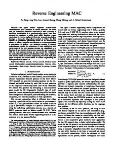
3. IFPUG counting rules 3.1 Manual counting rules Thirty five sub-steps have been inventoried by the authors' from the IFPUG-CPM standard in order to manually count an application. They can be regrouped into five major steps: determine the type of function point count, identify the boundary of the count, determine the unadjusted function point count, determine the value adjustment factor, compute the final adjusted count. A major portion of a counter time and effort is spent in the third major step: determining the unadjusted function point count (see figure 2). Especially to identify data and transactional function types. Once identified the counting procedure are quite straightforward.
2.2 Function Point supporting tools A number of proposals have been made to automate FP counts [25]. MacDonnell [15] studied nine functional size measurement methods and estimation models. All FSM methods were assessed against six criteria including the automation criteria. The automation criteria rated, on average, one of the lowest for all the FSM methods. He concluded that automation of FSM methods required further research effort. Some mechanized tools offer support for the manual count of function points. IFPUG categorized the support tools in three categories that were later extended to 10 categories in the research work of Mendes [18]. Category 3 of those classifications refer to the automatic FP counting tool. CASE vendors claim to support function points as part of their tool’s standard capabilities [12]. Mendes [18] surveyed eight suppliers of CASE that claim an automatic FP counting feature. From the suppliers surveyed only one vendor had a feature to calculate automatic FP counts from source code (Cobol). The survey revealed that no vendor claimed that they could automatically count all the entire steps of the FPA. Each one had at least one step requiring external intervention. Few high level presentations [6] [16] [17] and industry publications [5] [22] are available to describe some automatic FP implementation details. There is
Function Point Count*
Data Function Types
Internal Logical Files (ILF)
External Interface Files (EIF)
Transactional Function Types
External Inputs (EI)
External Outputs (EO)
External Inquiries (EQ)
* unadjusted FP count
Figure 2: Function Point counting steps To identify data function types and transactional function types fifty IFPUG rules apply. Thirteen rules (13) are associated with data function types and thirtyseven rules (37) are associated to transactional function types. As an example in identifying an external inquiry (EQ) one rule, which will be used as an example in section 4 of this paper, states that:
3
useful concept when trying to automate the identification of a transactional function type. To continue with our initial example, the following signature for an external inquiry (EQ) in this notation is:
‘The retrieved data does not contain derived data’. (Derived data: is data that requires processing other than direct retrieval and editing of information from ILF and/or EIF)’. The CPM rules are presented in natural language and must be subject to formal definition in order to automate them.
EQ
4. Formal Modeling of IFPUG Rules
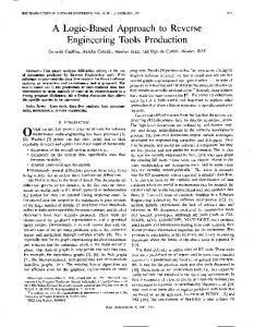
This signature can be interpreted in the following way. An external inquiry (EQ) is identified when the following condition apply: mandatory flows 1 and 2 are present, flow 3 is always absent and flow 4 is optional. Flow 1 means that the process at the center of the boundary receives data either from users, another process or from a file outside the boundary. Flow 2 means that the process sends data to users, another process or from a file outside the boundary. Flow 3, being 0, means that the process does not write to a file inside the boundary and finally, flow 4 means that the process optionally reads from a file within the boundary. Using this signature and figure 3 representation some formalism was established by Paton, Abran [20]. Let B denote the boundary used by the CPM, I be a distinct subset of entities which are labeled "Internal" with respect to the boundary B, E be a distinct subset of entities which are labeled "External" with respect to the same boundary B. Entities can be either processes p or files f. E corresponds to the complement of I with respect to the total set of entities. In other words E will be concerned with entities that are outside the boundary. Processes and files can be identified and counted using detailed practices described in the CPM counting procedures.
It was identified [19] [20] that the objects to be counted are not defined by the CPM and that much of the identification activity of data and transactional function types rely on the boundary and user perspective concepts. Figure 3 shows the boundary concept of the CPM with processes p, files f and users interactions being inside or outside the boundary. In this notation the process p being part of the count is at the center of the boundary. A process p is described by IFPUG as the smallest unit of functionality that can be perceived by the users. users
p Flow 1 f
Flow 2 p
Flow 4 f
Flow 3
p f
f
Boundary legend: f p
Flow 4 0/1
Figure 4 : Signature of EQ using notation of figure 3
4.1 Semi-formal representation
users
Flow 1 Flow 2 Flow 3 1 1 0
4.2 Extension of the formalism to include a logical to physical translation
: file (logical view) : process (at the smallest unit of functionality)
A refinement of the previous representation is presented here to represent the computational units and physical files that will be used as inputs to reverse engineering techniques and algorithms if they are to be used to mechanize the interpretation of the IFPUG counting rules. Computational units are distinguishable computational process for which a name exist, an internal status may exist, and a boundary can be defined. This concept takes different names depending on the environment used and the programming
: Data flow (Input / output)
Figure 3: Paton, Abran semi-formal representation This representation described by Paton, Abran [20] , later extended by Mendes [18], was used to develop a semi-formal notation that can identify the valid signatures (see figure 4) of transactional function types of FP based on the CPM rules. The signatures become a
4
languages. Example of computational units are modules, programming functions, objects, source code, and so on. A boundary b is defined as:
The chapter 4 of the CPM is dedicated at defining boundaries, dictating the rules and procedures for determining them. Function point human counters must master the identification and determination of a boundary to be certified. Input/output operations of computational units can be defined of terms of elementary operations get and put. These functions are introduced to simplify reasoning about complex I/O operations without losing in terms of generality. For a given computational unit, get returns the set of all the distinct Input operations which affect a single variable. The source component of the input is also identified. Similarly for a given computational unit, put returns the set of all the distinct output component operations that refer to a single variable. The target of the output is also identified with an identifier id. Formally:
b = { x / (x ∈ P) ∨ (x ∈ F)} A set of process is represented by P. A set of files is represented by F . The function: is_in_b: I × B → {True, False} identifies the entities within a certain boundary. Let C represent the set of system components defined as the union of computational units and user interfaces. An implemented boundary is defined as: ib = { x / (x ∈ pwrset ( C ) ) ∨ (x ∈ PF)}, where pwrset ( C ) is the power set of components and PF the set of physical files. Since B is the boundary as defined by the CPM let IB be the implemented boundary, then:
get: C → C put: C → C
× ID × ID
users
b_impl: B → IB is the function that associates a boundary b with its implementation ib. We can define the function:
users
p f
is_in_ib: C × IB → {True, False}
Flow 1 Flow 4
p
Flow 3
p_impl
( ∀p ∧
∈
Boundary
P, ( is_in_b(p,b) → is_in_ib( p_impl(p), ib))
b_impl
p_impl
Flow 1
b_impl = { /
Logical to physical translation
Flow 2
Flow 4
( ∀f ∈ F, ( is_in_b(f,b) → is_in_ib(f,ib)) } ,
f
f
f
which identifies the components within a certain implemented boundary. The function b_impl is determined by the following equation:
p
Flow 2
Flow 3
Implemented Boundary
where the function p_impl: P → pwrset ( C ) is the function that associates a process with its implementation in terms of its components. The components and the physical files associated with the function being counted can easily be identified and supplied to the automatic tool at that time. This additional counting activity can be done by the users and their counter after setting the boundary of the existing application in the initial step of the “construction count” of the organization. A boundary indicates the border between the application being measured and the external applications or the user domain. A boundary establishes what functions are included in the function point count.
additional legend: : Physical data file(s) of f : computational unit(s) of p
Figure 5: Implemented boundary The correspondence between logical and physical worlds (see figure 5) is made through the following assumption: p is an EQ for b ↔ p_impl(p) is an EQ for b_impl(b). That is, a process p is an EQ for a given boundary b if and only if the set of components
5
/ (ck ∈ F) ∧ (is_in_ib ( ck, impl(B))))
corresponding to the implementation of p is an EQ for the corresponding implemented boundary.
4.3 Representation of IFPUG rules Rule 4: The retrieved data does not contain derived data. ∪ put(ci) } → ∀ (ck, pid) ∈ { ci ∈ p_impl(p) ∪ get(ci) } / → ( ∃(cj, gid) ∈ { ci ∈ p_impl(p)
The following figure 6 defines for the first four CPM rules of an EQ the flow analysis based on the previous definitions. As an example in rule 1: p obtains some data from f, p or users in E corresponds to the following CPM rule: “An input request enters the application boundary”. Based on previous definition, these conditions can be interpreted as the existence of a
/ (var_def (gid) = var_ref( pid)) ∧ (def (gid) ∈ reaching_definitions (pid))))
component ck and an input operation (identified by the get identifier gid) such that:
Figure 6 : Formal representation of four CPM rules associated with an external inquiry (EQ)
- the input operation is performed by a component within the implemented boundary of b, and
- ck is not contained in the implemented boundary of
In figure 6, the var_def(gid) represents the computational unit variable which is assigned by the input operation gid and var_ref(pid) is the variable whose content is used in the output operation identified by pid. Var_ref and var_def functions are defined as follows: var_def : ID → V var_ref : ID → V
b. Similarly rules 2 or 3 can be expressed as shown in figure 6. In Figure 6, rules 1 to 3 are interpreted with Paton and Abran signature. The problem of determining the existence of a pair (Ck, pid1) can be converted into a problem of software analysis using control flow graph (CFG) path analysis. Rule 4 require a higher level analysis, namely static flow analysis. This rule is satisfied when no data from flow 1 and flow 4 is altered. This can be determined by observing if a computational unit variable which contains data read by an input operation is not altered prior to its use in an output operation.
They represent respectively the function that return the variable assigned by an input operation and the function that return the variable used by an output definition. Def and ref functions allow the domain translation from Input/Output operations to the sets of variables defined and used by the operations themselves. def: ID → DEF ref: ID → REF
Rule 1: p obtains some data from f,p or users in E. ∪ get (ci) } / ∃ (ck, gid) ∈ { ci ∈ p_impl(p) / not (is_in_ib (ck, b_impl(b)))
Let x ∈ DEF be a definition, the corresponding reaching definitions set can be defined as follows: x ∈ reaching_definitions (id) ↔
∃ s = / ∀ y ∈ s → def (y) ≠ x)
Rule 2: p writes some data to f, p or users in E. (CPM: Output results exit the application boundary) ∪ put (ci) } / ∃ (ck, pid) ∈ { ci ∈ p_impl(p) / not (is_in_ib ( ck, impl(b)))
Where def_pos(x) is a function that returns the identifier of a given definition x. In other words, x belongs to the reaching definition set at a given point id, if and only if a path s exists between the definition x and id in which x is not redefined.
Rule 3: p writes no data to an f in I. ∪ put (ci) } / not (∃ (ck, pid) ∈{ ci ∈ p_impl(p)
4.4 Propagation Analysis
1 (identified by the put identifier pid)
6
A first question that can be addressed is the precision of the terminology used by IFPUG and its relationship to source code analysis. Can expressions based on IFPUG terminology be precise ? The notion of processes and files is precise in the sense that they allow the repeated calculation of FP yielding the same results. The presented equations are precise in the sense that given a set of inputs to the equations, the results should be repeatable and consistent. Now, some of the inputs to the equations are coming from information extracted from the source code, while others will depend on human judgment. Literature review of section 2.2 identified that most existing support tools have human intervention. There is a need for an assessment of how much manual interaction will be required in this automated procedure to address the intention of the CPM rules of IFPUG. Some inaccuracies may arise since the automated FP counting procedure will most probably still have some human input judgment. Our procedure is precise, but may suffer from the same amount of inaccuracy as introduced by human interaction. We then rely on IFPUG training and certification that are in place to reduce the amount of inaccuracy introduced by human judgment. The consistency of the measurement is preserved also by means of human training and consensus reaching procedures of IFPUG. Consistency among different counters is achieved through the training and the certification. The variability among human counters has always improved as presented in the introduction of this paper. In the authors' opinion, FP counts obtained by the proposed automatic techniques should correlate quite well with those obtained by human counters. The extend of such a correlation, and therefore the accuracy of the proposed equations, will be determined by experimental results (posteriori) comparing automatic counts versus manual counts. The presented data flow analyses are "safe" in the sense that they take conservative decisions while approximating the dynamic behavior of program execution. Safe means here that the approximated solution may be a superset of the correct set of solutions, but no correct solutions are ever missed. In rule 1 in fig.6, for example, p may obtain some data from f, p, or users in E through a static path in the program Control Flow Graph (CFG) and so trigger rule 1 counting, although such a path may not be feasible and the corresponding data exchange may never be executed. At the same time, the "safe" approximation guarantees that no possible data exchange between f, p, or the users in E will never be missed by the analysis.
Additionally, for rule 4, we can cover the particular situation, shown in figure 7, where a variable could reach the output point through a series of copy propagations, while the original variable itself can be safely modified after the copy.
x = get () t =x x=1 put (t)
Figure 7 : Example of variable usage Rule 4 should be extended to cover this situation by using the definition propagation analysis as presented in figure 8. Rule 4 : The retrieved data does not contain derived data (with copy propagation). ∀ (ck, pid) ∈ { ∪ put(ci) } → ci ∈ p_impl(p) ∪ get(c) } / → ( ∃(cj, gid) ∈{ ci ∈ p_impl(p) / ( ∃ df ∈ reaching_definitions (pid) / / ( df ∈ copy_of (def (gid), def_pos(df)) ∧ var_def (df) = var_ref (pid))))
Figure 8 : Definition propagation Let x ∈ DEF, y ∈ REF be definitions, copy_of (x, id) can be defined as: copy_of (x,id) = { y / ((stm(id) = “var_def(x) = var_def(y)”) ∧
( x ∈ reaching_definitions (id) ) ∨ (y=x)) }
Several approaches to compute the reaching definitions are available [3]. Recently an approach with different levels of precision and performance for reaching definition analysis in an inter-procedural context was proposed in [23].
4.5 Precision for the interpretation of an IFPUG rule
7
In several applications, this approximation turns out to be definitely acceptable [24]. In the particular application of FP counting, it will be the role of the experiments to assess the amount of approximation introduced by the analyses and to assess its impact on counting. There could also be a bias in the measurement. Bias is the total systematic error as contrasted to random error. There may be one or more systematic error components contributing to the function point measurement error. The conservative approximation of data flow analysis may introduce a systematic bias towards super sets of the correct set of solutions. The extent of such a bias, will be determined by experimental results (posteriori) comparing automatic counts versus manual counts.
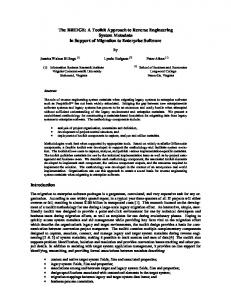
This is mainly because we have a separate research team working to resolve the data reverse engineering challenge associated with FP’s. Before counting the function points associated with this specific external inquiry the counter must identify the external inquiry. There are numerous rules that must be satisfied in order to validate that we have in fact an external inquiry to be counted. This paper specifically addressed automation using reverse engineering techniques to assess whether or not a rule is met for a specific external inquiry. It represent one of the many analyses that are required in figure 9. The technique presented in the paper will be used as part of a function to identify the external inquiry rules before the external inquiry is passed to the next steps of the identification procedure (FTR identification and DET identification in figure 9).
4.6 How to assess the IFPUG rules during source code analysis Source code (computational units that compose pn, user interfaces accessed by pn, Physical Files and data elements accessed by pn) ! CFG ! Analyses that identify an EQ for pn ! Analyses that identify FTR of an EQ for pn ! Analyses that identify DET of EQ for pn ! Counting of EQ FP’s for pn.
To understand where the individual IFPUG rules are assessed during source code analysis one must understand the counting procedure. The FPA requires the counter to follow sequential steps when counting. The counting procedure first identifies all the items that will then be counted in a second step. System partitioning is done in the following way: Manual FP counters are trained and certified to determine counting boundaries and system functional partitioning to represent the end user point of vu to be counted. Their work is done based on available system documents, system interfaces, database layouts and reports review as well as user interviews. At this point they can identify the physical components identified by Source Code in figure 9. If requirements are available they can be used, but one of the problems reverse engineering addresses is the possible discrepancy between the system "asdescribed" in the documents and the system "as-is" in the implementation. Therefore reverse engineering can be interesting also when requirements are indeed available. The equations presented in this paper constitute an approach to count FP's in an existing system "as-is". Once the boundary is defined, the counter starts with identifying Data Function Files (see figure 2, left side). Then he proceeds with the identification of Transactional Function Types (see figure 2, right side). Our example in this paper addresses one particular transactional function type called an external inquiry (EQ) and assumes that the Data Function Types and associated physical files have already been identified.
Figure 9 : Reverse Engineering Procedure for p counting FP’s of an EQ p
5. Conclusions and future work This approach for automating the evaluation of an IFPUG rule is new and original. We showed its conceptual feasibility on some specific EQ rules. The formal definition of the IFPUG rules is based on programming languages concepts and analysis. The evaluation of the IFPUG rules is performed by using flow analysis techniques. Some of these techniques, in particular reaching definitions analysis, use recent and sophisticated advances available in the literature. In this paper a new analysis called definition propagation was presented (see figure 8) for a more precise evaluation of an IFPUG rule. In general, it can be said that reverse engineering techniques for automatic FP counting directly from source code is a promising avenue. There is a number of reverse engineering techniques available that can be used and the need for an assessment of how much manual analysis is required in this procedure to address the intention of the CPM rules of IFPUG. We have
8
introduced formal definitions of four of the seven external inquiry rules of the CPM. Further work is in progress to refine the formalism, the selection of candidate reverse engineering techniques as well as the techniques themselves. Continuing research will address all the CPM rules of IFPUG and the development of related analysis techniques. Limits and approximations are necessary to achieve a high level of automation will be explored. Another interesting avenue of research is the empirical validation of the proposed approach by comparing the automated rule evaluation to a manual count. The project is at the stage of conceptual definition of counting equations and automatic tools to compute FP counts are envisaged, but not yet developed.
External inquiry (EQ): One of the three transactional function types representing the inquiry. f: A file. F: A set of files. File: For data function types, a logically related group of data, not the physical implementation of those group of data. File type referenced (FTR): An ILF or EIF read or maintained by a transactional function type. function types. Function point (FP): A measure that describe a unit of work product (from a functional perspective) suitable for quantifying application software. Function point Analysis (FPA): A standard method for measuring function point. get: A function that returns the set of all the distinct Input operation that affect a single variable for a given computational unit. gid: A get identifier. I: A distinct subset of entities which are labeled "Internal" with respect to the boundary B. Implemented boundary: An implemented boundary establishes what computational units and physical files address the functions are included in the function point count. ib: An implemented boundary. IB: A set of implemented boundaries. Internal logical file (ILF): One of the two data function types. Maintained: The ability to modify data through an elementary process. is_in_b: A function that identifies the entities within a certain boundary. is_in_ib: A function that identifies the components within a certain implemented boundary. Process: A process (represented by the symbol p) is described by IFPUG as the smallest unit of functionality that can be perceived by the user. p: A process. P: A set of processes. p_id: A put identifier. P_impl: A function that associates a process with its implementation in terms of its components. put: A function that returns the set of all the distinct Output component operation that refer to a single variable for a given computational unit. Record element type (RET): User recognizable subgroup of data elements within an ILF or EIF. Transactional function type: The functionality provided to the user to process data by an application. User(s): The person(s) or organization(s) that uses the measured application.
6. Glossary of terms ∪: The confluence operator, see reference [2]. b: A boundary. B: A set of boundaries. b_impl: The function that associates a boundary b with its implementation ib. Boundary: A boundary indicates the border between the application or project being measured and the external applications or the user domain. A boundary establishes what functions are included in the function point count. Also called ‘application boundary’. Components: The union of computational units and user interfaces for a process p. Also called system components. Computational units: Distinguishable computational process for which a name exist, an internal status may exist, and a boundary can be defined. Example of computational units are modules, program functions, objects, source code, and so on. Counter: Also known as ‘FP counter’ is an individual that measures FP and has obtained certification from IFPUG. Also known as a ‘certified’ counter. Data element type (DET): A unique user recognizable, nonrecursive field. Derived data: Data that requires processing other than direct retrieval and editing of information from internal logical files and/or external interface files. E: A distinct subset of entities which are labeled "External" with respect to the same boundary B. E corresponds to the complement of I with respect to the total set of entities. In other words E will be concerned with entities that are outside the boundary. Elementary process: The smallest unit of activity that is meaningful to the end user in the business. Entities: Entities can be either processes p or files f.
9
7. References
École Polytechnique de Montréal, Génie Électrique et Informatique, Mars 1994. [2] A. J. Albrecht, "Measuring Application Development Productivity," Proceedings of the IBM Application Development Symposium, Monterey, CA, October 1979, pp. 83-92.
[1] A.Abran, Analyse du processus de mesure des points de fonction, Thèse de doctorat, Université de Montréal,
10
[3] A.V. Aho, R. Sethi, and J.D. Ullman. Compilers: Principles, Techniques, and Tools. Addison-Wesley, Reading, MA, 1986. [4] D.C.Atkinson, W.G.Griswold, The Design of Wholeth Program Analysis Tools, 18 International Conference on Software Engineering, March 25-29, Berlin, Germany, pp.16., 1996. [5] R.Banker et al.: Automating Output Size and Reuse Metrics in an Repository-Based Computer-Aided Sofware Engineering (CASE) Environment, IEEE Transactions on Software Engineering, Vol 20. No 3., March 1994, pp. 169-187; [6] D.Brown, Automated Function point Counting - Myth or Reality, Proceedings of the IFPUG Fall Conference October 1990, p. 168-180. [7] M.Hotle, Application Development & Management Strategies (ADM), Strategic Analysis Report, Gartner Group, November 4, 1996, 31p. [8] IFPUG, Function Point Counting Practices Manual Release 4.0. Counting Practices Committee, The international Function Point Users Group (IFPUG), 1994. [9] IFPUG, Function Point Counting Practices: Case Studies, Release 1.0, Counting Practices Committee, The international Function Point Users Group (IFPUG), July 1994. [10] ISO/IEC DIS 14143-1.2 Draft International Standard, Information Technology - Software MeasurementFunctional Size Measurement, Part 1 Definition of Concepts, International Organization for Standardization, International Electrotechnical Commission, 1997. [11] D.R.Jefferey, G.C.Low, and M.Barnes, A comparison of Function Point Counting Techniques, IEEE Transaction on Software Engineering, Vol. 19, No 5, May 1993. [12] C.Jones, Function Points and CASE Tools, Managing System Development, April 1995, pp. 1-5. [13] C.Jones, Applied Software Measurement, McGraw-Hill, Software Engineering Series, 1991.
[14] C.F.Kemerer, Reliability of Function Points Measurement: A field experiment, MIT Sloan School of Management, WP#216, 1990. [15] S.G.MacDonell, Comparative review of functional complexity assessment methods for effort estimation, Software Engineering Journal, May 1994, pp. 107-116. [16] F.A.Mazzucco, Automation of Function Point Counting - An Update, Proceedings of the IFPUG Conference, 1990 Spring conference, Orlando FL, 16 p. [17] F.A.Mazzucco, IEF - Automatic Function Point Count, Proceedings of the 1992 IFPUG Conference, April 2-5, 1992, Baltimore MA p. 169-181. [18] Mendes,O, Développement d’un protocole d’évaluation pour les outils informatisés de comptage automatique de points de fonction. Rapport d’activité de Synthèse, Maîtrise en Informatique de Gestion. December 1996. [19] K. Paton et A.Abran, TABCOUNT - A Table Based System for Counting Function Points. (non published technical report), Quebec University in Montral, 1995. [20] K. Paton et A.Abran, A Formal Notation For The Rules Of Function Point Analysis. Research Report #247, Département de mathématique et d’informatique UQAM, 44 pages, 1995. [21] E.E.Rudolph, Precision of Function Point Counts Analysis, IFPUG Spring Conference, April 3-6 1989, SanDiego, California, 1989. Quebec University in Montreal, 185p. [22] T.Sample, T.Hill, The Architecture of a Reverse Engineering Data Model Discovery Process, EDS Technical Journal, Vol. 7, No. 1, 1993. [23] P.Tonella, G.Antoniol, R.Finsten, E.Merlo, Variable Precision Reaching Definitions Analysis for Software Maintenance, Proceedings of the Euromicro-96, 1996. [24] P.Tonella, R.Fiutem, E.Merlo, G.Antoniol, Variable Precision Reaching Definitions Analysis for Software Maintenance, IRST Technical Report 9602-01, February 1996. [25] G.E. Wittig, Artificial Neural Networks with Function Point Analysis for Software Development Effort Estimation, Bond University, academic dissertation, January 1995.
11