A Simulation Environment for Modeling and Development of Algorithms for Ensembles of Mobile Microsystems Jonathan Finka , Tom Collinsb , Vijay Kumara , Yasamin Mostofic , John Barasd , Brian Sadlere a University
of Pennsylvania, Philadelphia, PA, USA Institute of Technology, Atlanta, GA, USA c University of New Mexico, Albuquerque, NM, USA d University of Maryland, College Park, MD, USA e Army Research Laboratories, Adelphi, MD, USA
b Georgia
ABSTRACT The vision for the Micro Autonomous Systems Technologies MAST program is to develop autonomous, multifunctional, collaborative ensembles of agile, mobile microsystems to enhance tactical situational awareness in urban and complex terrain for small unit operations. Central to this vision is the ability to have multiple, heterogeneous autonomous assets to function as a single cohesive unit, that is adaptable, responsive to human commands and resilient to adversarial conditions. This paper represents an effort to develop a simulation environment for studying control, sensing, communication, perception, and planning methodologies and algorithms. Keywords: Robotics, Simulation, Communication
1. INTRODUCTION Simulation based design is an essential step in the development of algorithms for any complex robotic system. It allows rapid development with new models as well as the ability to enforce simplifying assumptions that can later be incrementally removed to aid in hierarchical validation and verification of new solutions to a problem. Additionally, a common simulation environment becomes an enabling tool for geographically distant collaboration where a common hardware implementation is often impossible. It allows researchers to not only develop algorithms using a common set of assumptions and constraints but also simplifies the integration step where a set of solutions must be used in concert to solve a higher-level problem. Thus, we seek to design and implement a collaborative simulation environment for the MAST project with the necessary tools to explore a wide range of problem areas involving teams consisting of tens of robots in DoD-relevant scenarios. The MAST simulation environment allows three-dimensional simulation of mobility, perception, and communication, which will be modular and lend itself to dynamic updating. It is built using the Gazebo (version 0.8) robotic simulation environment. Gazebo provides 3D dynamics and rendering services such that we can provide and distribute accurate models of the platforms used in the MAST project. This includes models of wheeled and legged robots, models of quadrotors, and models of such three-dimensional sensors as cameras and laser rangefinders. Gazebo does not provide any type of communication simulation. To overcome this limitation we have added a networking layer that uses environmental and state information to provide realistic modeling of the communication channels. In order to do so, we generate link qualities probabilistically such that every agent experiences a multi-scale stochastic channel whose average and correlation properties are dictated by the specifications of the environment. We procede as follows. In Sec. 2 we survey existing work and software for general robotics development, robotic simulation, and communication network simulation. With existing tools in mind we lay out an overview of the MAST simulation environment in Sec. 3. Specific models that are currently implemented and to be used within the MAST simulation environment are detailed in Sec. 4. In Sec. 5 we provide experimental validation for the suitability and accuracy of our simulation implementation with respect to a real environment with actual robotic platforms. Finally, in Sec. 6 we provide a simulation example of a connectivity control problem. Send correspondence to
[email protected]
1
2. PREVIOUS WORK In order to foster collaboration and take advantage of previous work, we seek to employ existing open-source software in the design of our simulation environment. In this way, we reduce the overhead of building a system from scratch and can take advantage of advancements as each component of the simulation architecture evolves.
2.1 Software Frameworks for Robotics The goal of this work is to develop a shared environment for the collaborative exploration of multiple problem areas in relation to the MAST program. Though algorithmic implementations are developed independently using only essential dependencies, integration requires a common language to describe the input/output structure that is prevalent in engineered systems. While we are not seeking to solve the entire software architecture problem (including problems such as scheduling and resource allocation), it is necessary to address issues such as abstract interfacing and communication capabilities. Given adherence to writing and using modular, reusable code, it is inevitable that some pieces of even a highly customized multi-robot system will already exist. This could range from a modern operating system to libraries that provide commonly used algorithms. Several open and closed source software libraries are available that support robotics and generally provide some or all of the following: • an architecture with commonly defined interfaces so that software modules can be written that encourage good design practices and reuse; • a middleware library that allows both local and networked communication efficiently between modules; • a set of low-level drivers for robotic hardware; and • a simulation environment to substitute when hardware is not necessary or available. As such a system is extremely complex, most choose to not build a home-grown solution. Additionally, selecting an existing system with a large user-base and active development can lead to beneficial collaboration. There are a number of such systems currently available: • Microsoft Robotics Studio:1 Developed recently by Microsoft, this package provides a services-oriented architecture with both a visual programming environment and physics-based simulator. It relies on proprietary modules to control and connect user-defined software modules in any language supported by Microsoft Visual Studio. This software dictates the use of a closed-source Windows operating system. • ORCA:2 This project leverages the separately developed Ice3 middleware which provides a host of features from a well-supported open-source project including easy interface definitions and tools to manage services, deployment, and event messaging. ORCA is released under the LGPL and GPL licenses and can be compiled on both Linux and Windows operating systems. • OROCOS:4 The Open Robot Control Software (OROCOS) project has focused its development on real-time constraints that are often necessary in industrial robotics applications. OROCOS provides a component system using CORBA as a middleware as well as libraries for kinematics/dynamics and Bayesian filtering. • Yet Another Robot Platform (YARP):5 Intended primarily for humanoid robotics, YARP provides both interface and communication abstractions that allow for modular systems and code reuse. It is developed as an open source project and compiles from source code on both Windows and Unix variants. • Player:6 Probably the most widely used robotics software package, the Player/Stage/Gazebo (PSG) project consists of libraries that provide access to communcation and interface functionality. The robot “server” Player provides an architecture where many modules (known as “drivers”) can be independently written and connected through a custom middleware relying on TCP communication. Users are also able to write simpler “client” applications that can connect to and command modules running on a Player server. The project is developed for Unix-variant operating systems (e.g. Linux and Mac OS X). 2
• MissionLab:7 Developed originally as a mission specification toolset allowing users to specify combinations and sequences of robot behaviors to accomplish tasks, MissionLab includes drivers for a range of robotic platforms as well as a limited simulation capability. It also includes task assignment mechanisms, multple path planners, and the ability to use other simulators for higher fidelity or user interaction.
2.2 Simulators for Robotics A robotics simulation environment is essentially a specialization of general purpose dynamic simulators that allows for integrated modeling of sensors and actuators. The following are examples of simulators currently available for robotics. • Microsoft Robotics Studio:1 The simulation component of the Microsoft Robotics Studio is based on the TM R NVIDIA!PhysX engine which provides dynamic simulation with the capability for hardware acceleration • WebotsTM :8 A simulation environment for mobile robots relying on the Open Dynamics Engine (ode)9 for physically accurate models, WebotsTM has the capability of exporting control programs to a few select embedded robotic platforms. It is commercially available for multiple platforms (Windows, Linux, and Mac OS X) in a professional and less-enabled educational version. • USARSim:10 The Unified System for Automation and Robot Simulation (USARSim) was created to enable useful development of robotic algorithms for urban search and rescue missions. It relies heavily on the proprietary Unreal Tournament 2004 game engine which provides facilities for graphical rendering through a documented API and dynamic simulation through the underlying Karma physics engine from MathEngine. USARSim provides efficient simulation tools with a full suite of modelling tools and is particularly suited for work in immersive environments. • Gazebo:11 Like Webots TM , Gazebo relies on ODE9 for dynamics simulation including rigid bodies and a variety of joint types. It utilizes the Ogre3D project,12 an open-source OpenGL based rendering environment, for visualization and camera sensors. Worlds and models are described in XML files for fast creation of new environments. Additionally, complex visual effects like lighting, shadows and fog are enabled through Ogre3D.
2.3 Simulators for Radio Communications & Wireless Networks In general, a wireless network simulator can be considered with respect to the standard OSI networking layers. Though our evaluation currently focuses on the physical layer including the model of radio-signal propagation in complex indoor environments, higher layers including contention resolution and routing protocols obviously play a large role in any cooperative multi-robot system. For our purposes, we need to have the following capabilities: • the ability to handle dynamic environments;
• modelling of wireless radio signal propagation;
• dynamic models of robotic systems - the wireless nodes in our system are robots under autonomous control and thus very few assumptions can be made with respect to their motion patterns; and • ability to simulate protocol for contention resolution. Finally, we need the simulator to be realistic and efficient. In order to develop control algorithms it is beneficial to operate as close to real-time as possible. While there are numerous simulators used extensively in the wireless networking and mobile ad-hoc wireless networking (MANET) communities, we will refer to the two most widely utilized (according to analysis in13 ) GloMoSim 14 and NS-2 .15 Both simulators are designed to simulate large networks (thousands of nodes) with a variety of protocols for contention resolution and routing. Though the default models of wireless radio-signal propagation are limited, one can achieve more realistic models that take specific environmental obstacles into account.16, 17 3
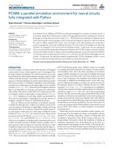
Figure 1. Simulator Architecture
3. SIMULATION ARCHITECTURE & MODELLING Arguably more important than the choice or development of particular pieces of software to implement simulation or algorithms is the design of the underlying software architecture. This applies to both experiments and simulation but we will focus on the simulation instance here. The primary design goal driving our simulation environment design is to create a collaborative environment so that multiple researchers can independently develop and test algorithms with common constraints and limited concerns for later integration. With that in mind, we have laid out the architecture depicted in Fig. 1. Given a constant implementation of the middleware, specific software for dynamic simulation, communications, or even algorithms must only conform to the specifications dictated by the middleware. We have chosen to center the simulation architecture around Player as it has widespread usage and existing connections to multiple simulation environments. While this work will focus on Gazebo as a robotic simulator due to its open-source nature and the ease with which models an capabilities can be added, USARSim is also a feasible choice specifically for simulations requiring an immersive environment. Additionally, note that choice of Player as a middleware does not preclude the use of MissionLab as a wrapper for front-end tasking.
3.1 Dynamics/Perception Gazebo relies on the Open Dynamics Engine (ODE) for physics simulation and Ogre for visual rendering. In ODE, models can be constructed from unions of primitives or triangle meshes connected by a variety of joint types. Ogre’s capabilities include complex materials, hardware shader support, lighting, shadows, fog, and other graphical effects that can combine to generate realistic environments. Additionally, Ogre’s scene-management capabilities make it simple to attach camera objects to robot models in order to facilitate visual sensors.
3.2 Middleware The robotics middleware (discussed in Sect. 2.1) is the key to achieving seamless integration between components. The middleware offers clearly defined interfaces that: 1. Permit software to be reused for multiple experiments. 2. Allow new hardware or sensors to be rapidly introduced to the system. 3. Enable tight integration between simulation and the real-world. 4. Facilitate collaboration.
4
The third and fourth points emphasize a benefit of common middleware and interfaces. By defining a common interface structure, simulation environments may be enabled to support the interfaces. This allows code written for a simulation environment to be gracefully transitioned to the hardware. The same code that runs on a local computer in simulation will function in the same way on the robots. Additionally, software written using common robotics middleware allows for collaborations by requiring common interfaces between software. Player provides middleware capabilities for sending data between controllers/agents via particular interface specifications. Natively, Player requires a static communication topology over a reliable transport protocol – TCP.
3.3 Communication We have extended Player’s functionality by defining a custom interface for typical peer-to-peer messaging and providing a code-base which allows for dynamic network connections that are throttled by a discrete packet simulator that evaluates each requested transmission. By adapting Player’s capabilities, we retain the advantages of code modularity and strict data interfacing. 3.3.1 Abstracted Peer-to-Peer Messaging We have defined an abstracted representation of peer-to-peer messaging such that each message (of arbitrary size) consists of a source, destination, and payload. Fields are also included to record received-signal-strength and timestamps. In this way, our messaging is invariant to the underlying communication protocol or radio. In other words, networking layers above the physical layer can be implemented either through the communication simulator backend described next or via other Player modules. 3.3.2 Communication Simulator Backend The intent of the communication simulator backend is to match the behavior of a generic wireless device. Since the capabilities provided by different devices such as IEEE 802.11, IEEE 802.15.4 (Zigbee TM ), and Bluetooth vary with respect to addressing and routing, the communication simulator backend must be able to operate in a number of different modes. Another way to consider the communication simulator backend is as an adaptor to whatever software is providing the actual discrete event simulation necessary. It must manage the current state of the environment from the physics simulator as well as interface the communication requests made by other algorithms via the Player architecture to the underlying communication simulator. This design also fosters collaboration as the plug-in structure allows new communication simulators to be incorporated via a small set of callback functions. It should be noted that while in this work we focus on presenting specific models for radio signal propagation, the capability exists to alternatively rely on more complex simulation of the wireless network through software packages described in Sec. 2.3 which incorporate protocol definitions on top of radio propagation.
4. MODELS The development of experimental MAST robotic platforms is a multi-year effort just underway across the four MAST centers (Integrator, Microelectronics, Micro-mechanical Systems, and Autonomy). At this point, participating institutions are relying on existing surrogate platforms. Within this simulation architecture, we have developed models that replicate the MAST surrogate platforms. Additionally, we have implemented a simple communication model that demonstrates the current communication capabilities through experimental verification with actual radio hardware.
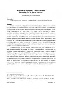
4.1 Robots 4.1.1 Scarab The Scarab platform depicted in Fig. 2(d) is equipped with a differential drive axle placed at the center of the length of the robot with a 21 cm wheel base. Two stepper motors drive 10cm wheels with a 4.4:1 gear reduction, resulting in a nominal holding torque of 28.2 kg-cm at the axle. The Scarab is typically equipped with a Hokuyo URG laser range finder. The entire platform is approximately 20 × 13.5 × 22.2 cm3 with a mass of 8 kg. 5
(a)
(b)
(c)
(d)
(e)
(f)
Figure 2. Figures of simulated robot models (a-c) with their actual counterparts (d-f).
Using these specifications, we are able to generate an accurate simulation model of the Scarab (Fig. 2(a) that provides an identical interface to the drive system and laser range finder through Player interfaces. Additive Gaussian noise is applied to the actuation and sensors to match experimental data. 4.1.2 RespondBot RDK The RDK depicted in Fig. 2(e) is a six-legged platform designed by Sandbox Innovations18 to provide high speed traversal of uneven terrain. It measures 35 × 30 × 10 cm3 with a mass of 2.7 kg and a payload of 3 kg. It has compliant legs and offers many challenges in simulation modelling. A rigid body approximation has been developed and shown to be sufficient for slow gaits (see Fig. 2(b)). 4.1.3 Quadrotor To provide a platform with aerial capabilities, we have implemented a model of the AscTec Hummingbird quadrotor19 from Ascending Technologies GmbH as shown in FIg. 2(f). The quadrotor has internal stabilization electronics that control rotor speeds to achieve a desired roll and pitch angle relative to the inertial frame so that our input consists of thrust, yaw velocity, and desired attitude angles. By assuming internal PID controllers on each of the inputs, we have designed a simulation model that is accurate enough to develop higher level controllers for velocity and position control in simulation. The simulation model is depicted in Fig. 2(c).
4.2 Communication Channels Indoor radio signal propagation is generally considered to be an extremely uncertain and complex process with heavy correlation to environmental features ranging from electromagnetic interference to physical obstacles. However, due to the pervasiveness of wireless communication needs in and around buildings, there is an extensive body of literature devoted to understanding and modeling the radio propagation process. We seek to draw on this work in order to develop tools that allow us to fully incorporate radio signal information into our estimation and control tasks. Development of models for indoor wave propagation can be classified into four categories: simplified path loss models, empirical direct-path models, empirical multi-path models, and ray optical models.20 While ray optical models include the possibility of simulating complex indoor phenomena such as fast-fading and corridor wave-guiding effects, only some approaches such as21 provide efficient computational methods. 6
4.2.1 Simplified path loss models The most basic formulation, these models do not incorporate information about specific obstacles in the environment. Power-loss throughout the environment is computed as a function of the distance between antennas d and fit to the entire environment by a power decay n so that loss (in dB) is L = L0 + 10n · log(d) where L0 is a measured loss at 1 m. The decay parameter n must be experimentally fit for each environment. 4.2.2 Empirical direct-path models These models consider the line-segment connecting the source and receiver antenna. Obstacles along the transmission path are considered and result in path-loss prediction that is related to the number and type of obstacles in addition to the total path-length. A typical model (and one we have currently implemented) is the multi-wall model from22 where path-loss is given by Lmwm = L0 + 10n · log(d) +
N !
ki Li
i=1
where N is the number of wall-types, ki is the number of walls penetrated with type i, and Li is the loss factor for a wall of type i. The model is adjusted to the environment by tuning n and Li . 4.2.3 Statistical channel models Additionally, one can consider models that take into account the probabilistic nature of radio signal propagation. In fact, in extremely complex environments, a probabilistic model based on the exponential distribution can be used to simulate behavior due to multipath fading effects such that the average behavior becomes the simplified path loss model in Sec.4.2.1. This type of model was used in the MAST scenario described in.23
5. VERIFICATION Verification of the simulation architecture with respect to Player as a middleware and the Scarab platform is available in.24 Similarly, the work in25 was originally developed using the simulated models of the quadrotor robots described above. In order to validate the structure and implementation of the communication capabilities, extensive experiments26 were conducted to densely sample received signal strength in an indoor environment using a Zigbee radio. The raw data collected in these trials is shown in Fig. 3(a). Given a complete description of our experimental environment and the location of both transmitting and receiving robot, we can compute a description of the direct radio signal path including total distance and wall intersections. By fitting the parameters described in Sec. 4.2.2 with gradient free optimization methods, we are able to closely match the model with the average behavior across our trial as depicted in Figs. 3(b),3(c),3(d). The result of parameter optimization is the following: L0 = −12.9, n = 1.7, L1 = 4.0 ∗ .
6. CASE STUDY: CONTROL & PLANNING FOR CONNECTIVITY As an example of the functionality provided by the simulator, we have developed an example algorithm for connectivity control in an indoor environment. In practice, keeping received signal strength indicators (RSSI) above some minimum value has numerous benefits including reduced power consumption and higher bandwidth. The problem posed here is one of sending a single robot to a desired location in the environment to complete a sensing task while maintaining high quality connectivity back to a base station. We are not addressing issues of resource allocation or leader selection. The algorithm operates on a precomputed roadmap for the environment so that the connectivity control is reduced to control along a one dimensional manifold. By modulating each robot’s speed according to a switching
7
Top View
10m
RSSI
(b)
(c)
Side View
x
(a)
(d)
Figure 3. Visualization of full Zigbee data set consisting of over 20, 000 samples from top-view and side-view which demonstrates that radio signal propagation is in fact a stochastic process with uncertainty. Comparison of experimental data with the stationary robot at (0, 0). Figure 3(b) depicts average behavior when samples are grouped in 0.25 m cells. Figure 3(c) shows the result of applying the same averaging procedure to simulated samples. Figure 3(d) shows the error between the simulated and experimentally determined RSSI as a histogram representation with bins determined by the average RSSI error between each cell in simulation and experiment.
(a)
(b)
(c)
(d)
Figure 4. Snapshots from connectivity control simulation. Fig. 4(d) clearly demonstrates the benefit of an accurate simulation engine for radio communications - the robots in the lower left are closer in euclidian space due to the obstacle in the environment and the necessity to maintain desired RSSI.
8
RSSI !40
!50
!60
!70
!80
0
2000
4000
6000
8000
Figure 5. Trace of Leader (red) and Follower (blue) RSSI. Note that a minimum RSSI of approximately −60dBm is maintained.
function over the measured RSSI, the robots are extended as needed along the roadmap from the base station to the desired sensing location. Figure 4 depicts several snapshots from the simulation. The switching function that dictates robot speed is constructed such that equilibrium occurs with RSSI = −60 dBm. Figure 5 demonstrates that the decentralized controllers are able to acheive the desired signal quality. Note that the strength of the simulation architecture we have proposed is that the algorithm is unaware of the details of the communication channel. It relies only on the abstracted messaging representation that embeds RSSI measurement with the message payload (much like actual radio hardware).
REFERENCES [1] “Microsoft Robotics Studio SDK.” http://msdn.microsoft.com/robotics. [2] A. Brooks, T. Kaupp, A. Makarenko, S. B. Williams, and A. Oreback, Software Engineering for Experimental Robotics, vol. 30 of Springer Tracts in Advanced Robotics, pp. 231–251. Springer Berlin, 2007. [3] “Internet Communications Engine (ICE).” http://www.zeroc.com/ice.html. [4] H. Bruyninckx, “Open robot control software: the OROCOS project,” in Proc. of the IEEE Int. Conf. on Robotics and Automation, 3, pp. 2523–2528, (Seoul, Korea), May 2001. [5] “Yet Another Robot Platform.” http://eris.liralab.it/yarp. [6] B. P. Gerkey, R. T. Vaughan, and A. Howard, “The Player/Stage Project: Tools for multi-robot and distributed sensor systems,” in Proc. of the Int. Conf. on Advanced Robotics, pp. 317–323, (Coimbra, Portugal), June 2003. [7] D. MacKenzie, R. Arkin, and J. Cameron, “Multiagent mission specification and execution,” Autonomous Robots 4(1), pp. 29–52, 1997. [8] “WebotsTM , fast prototyping and simulation of mobile robots.” http://www.cyberbotics.com/products/webots. [9] “Open Dynamics Engine.” http://www.ode.org. [10] S. Balakirsky, C. Scrapper, S. Carpin, and M. Lewis, “UsarSim: providing a framework for multirobot performance evaluation,” in Proceedings of PerMIS, 2006, 2006. [11] N. Koenig and A. Howard, “Design and use paradigms for gazebo, an open-source multi-robot simulator,” in 2004 IEEE/RSJ International Conference on Intelligent Robots and Systems, 2004.(IROS 2004). Proceedings, 3, 2004. [12] “Ogre3d.” http://www.ogre3d.org. [13] S. Kurkowski, T. Camp, and M. Colagrosso, “Manet simulation studies: the incredibles,” Mobile Computing and Communications Review 9(4), pp. 50–61, 2005. [14] L. Bajaj, M. Takai, R. Ahuja, K. Tang, R. Bagrodia, and M. Gerla, “GloMoSim: A scalable network simulation environment,” UCLA Computer Science Department Technical Report 990027, 1999. [15] “The Network Simulator ns-2 (v2.1b8a).” http://www.isi.edu/nsnam/ns/, October 2001. ∗
In these experiments we assume a single wall-type
9
[16] M. Gunes, M. Wenig, and A. Zimmermann, “Improving manet simulation results - deploying realistic mobility and radio wave propagation models,” Computers and Communications, 2007. ISCC 2007. 12th IEEE Symposium on , pp. 39–44, July 2007. [17] K. Sridhar, S. Hao, M. Chan, and A. Ananda, “Egress: Environment for generating realistic scenarios for simulations,” Distributed Simulation and Real-Time Applications, 2006. DS-RT’06. Tenth IEEE International Symposium on , pp. 15–24, Oct. 2006. [18] “Sandbox innovations.” http://sandboxinnovations.com. [19] “Ascending Technologies, GmbH.” http://www.asctec.de. [20] G. Wolfle, P. Wertz, and F. M. Landstorfer, “Performance, accuracy and generalization capability of indoor propagation models in different types of buildings,” in IEEE Int. Symposium on Personal, Indoor, and Mobile Radio Communications, (Osaka, Japan), Sept. 1999. [21] J. M. Gorce, K. Jaffres-Runser, and G. de la Roche, “Deterministic approach for fast simulations of indoor radio wave propagation,” IEEE Transactions on Antennas and Propagation 55, pp. 938–948, Mar. 2007. [22] E. Damosso, ed., Digital Mobile Radio: COST 231 View on the Evolution towards 3rd Generation Systems. The European Comission, 1998. [23] A. Ghaffarkhah and Y. Mostofi, “Communication-aware navigation functions for cooperative target tracking,” in Proc. of the American Control Conf., 2009. to appear. [24] N. Michael, J. Fink, and V. Kumar, “Experimental testbed for large multi-robot teams: Verification and validation,” IEEE Robotics and Automation Magazine 15, pp. 53–61, Mar. 2008. [25] N. Michael, J. Fink, and V. Kumar, “Cooperative manipulation and transportation with aerial robots,” in Robotics: Science and Systems, (Seattle, WA), June 2009. Submitted. [26] J. Fink, N. Michael, A. Kushleyev, and V. Kumar, “Experimental characterization of radio signal propagation in indoor environments with application to estimation and control,” in Proc. of the IEEE/RSJ Int. Conf. on Intelligent Robots and Systems, (St. Louis, MO), Oct. 2009. Submitted.
10