A simulation tool has been designed by which students of a basic course on computer architecture can get acquainted with the principles of how a computer ...
ISBN: 978-972-8924-42-3 © 2007 IADIS
A SIMULATION TOOL SUPPORTING A BASIC COURSE ON COMPUTER ARCHITECTURE Eladio Gutiérrez, Sergio Romero, María A. Trenas Dpto. Arquitectura Computadores. Universidad de Málaga E.T.S.I. Informática, Campus de Teatinos, E-29071 Málaga, Spain
ABSTRACT A simulation tool has been designed by which students of a basic course on computer architecture can get acquainted with the principles of how a computer works at the low level. In the last years, laboratory assignments for this course consisted on the design and simulation of a reduced instruction set computer architecture using a CAD tool and a schematic design entry. This kind of low level simulation allows the student to observe how the execution of a machine program progresses along each of the machine cycles. But such a low level view of the computer system is not very inviting for a beginner and there exists the risk of his loosing the perspective of the whole system. Our simulation tool allows the students to easily cover the gap between the software level and the hardware level: they use the same computer architecture they will implement at the laboratory. This learning object (LO) can be used both as a demonstration tool, helping the teachers in their classes, or as a self-learning tool, used by the students to improve their knowledge of computer architecture and instruction cycle. KEYWORDS Learning Object, computer architecture simulator, laboratory work, HW-SW interface.
1. INTRODUCTION Computer Technology subject has an important practical load, concretely 3.6 practical European credits from 7.2. The main goal of this course is to introduce how the central processing unit (CPU) of a computer system works at the register transfer level, covering the gap between the machine and the assembly languages. To this end, a simplified version of a MIPS processor (Patterson & Hennessy 2005, Corbera et al. 2006) is explained and several examples of program execution are presented in classroom. From this starting point, students must develop their own circuit designs and simulate them using Xilinx Foundation as CAD tool. Teachers have usually followed a bottom-up methodology for this subject, i.e., starting from basic elements (elementary circuits) a complex item (CPU) is built up. From our experience, students need to reach a high degree of detail when implementing digital circuits in order to perform successfully these practices. Unfortunately, this fact gives rise to a side effect: they lose the big picture while focusing on implementation issues. Thus, the CPU behavior is not correctly comprehended up to midterm. In contrast to this approach, a top-down methodology appears to be more suitable with the aim of obtaining a global view of the CPU functionality. This way, new learning objects capable of illustrating the CPU behavior are required to visualize simultaneously the different studied levels: assembly instruction execution, that is, execution of a whole instruction cycle; and register transfer level, where we need to illustrate which are the activated datapaths for each of the machine cycles. After our experience, we find it is important for students at this degree to visualize low level simulation both as an animation over the schematic design of the CPU data-path, as well as a cronogram of the different circuit signals, as the one they will obtain when working with the CAD tool. This is not possible with other simulators of the MIPS ISA level, such us PCSpim, Mipslt or MIPS R2000 . In this paper we describe a simulation tool developed to help student to fix and improve their knowledge of the CPU internal operations.
358
IADIS International Conference e-Learning 2007
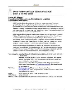
Figure 1. Main window of the simulation tool.
2. SIMULATION TOOL DESCRIPTION The main window of the simulation tool is depicted in Fig. 1. It includes four window frames showing, in turn, the content of the general purpose registers, the content of the memory, a waveform viewer and the CPU data-path. The memory content window is also divided into two sides, one with the numerical value of every memory location and the other one with the assembly code in the case of instructions. When starting to work with the application, the user can choose among four options: selecting an assembler source code, writing a new code, loading a binary file into memory or modifying directly the content of the memory and/or register contents. If the user decides to use the first or the second option, the assembler code must be compiled and loaded into the memory. At this stage, a simulation can be now performed. The simulation output is presented as digital waveforms of the selected elements, i.e. registers, or functional unit. The signal outputs are combined into buses, giving their contents in binary, decimal or
359
ISBN: 978-972-8924-42-3 © 2007 IADIS
hexadecimal format. This representation is usually found in generic digital circuit simulators. So beginners can familiarize with this format before they face up to such complex simulators. The application also includes an editor that allows users to write programs in machine code or in assembler language using labels, variable names and highlighting syntax errors. Application performs a user driven simulation running step by step. Time step unit can be either a clock cycle or a complete instruction execution. Clock cycles in waveform view are associated to different colours depending on which stage (fetch, decode,…) is involved. At the end of a time step, all involved elements are highlighted in the data-path view: registers, buses and memory location if any. Values of functional units can be checked by placing the mouse pointer over them. Anyway, the content of such elements can be modified by the user dynamically during the simulation. Implementing the application with Java technology ensured the portability. This allows the simulation tool to be used on different platforms or to be easily embedded in a web-based environment. After all, it is intended to be used both by the teachers, as a demonstration tool, as well as a self-pace learning tool for the students. To this end the tool is provided as a resource in the moodle platform of the University of Malaga, where it is associated with tasks, designed to guide students in their work, and a forum, to gain feedback from other students and teachers.
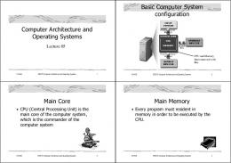
3. CONCLUSIONS AND EVALUATION In this paper a learning object useful for the teaching of a basic course on Computer Architecture has been introduced. This resource offers a visual simulation environment that helps not only teachers in their classroom explanations but also students with their homework. Such simulator is a good complement for a top-down approach to computer design before dealing with implementation details derived from the use of generic digital circuit development tools. Our tool allows users to easily link three different concepts: CPU behavior at instruction cycle, clock cycle level and the assembly code. For teachers, it has been a valuable help in their expositions. Direct observation of the classroom, as well as discussions with students, did confirm they found it to be a good complement to the subject. This point was also supported by our own students’ surveys. Fig. 2 shows results obtained for the questions related to the simulator.
Figure 2. Results of the students’ survey. Responses range from 5, a ‘stronly agree’ down to 1, a ‘strongly disagree’.
REFERENCES Xilinx: The Programmable Logic Company. Available at: http://www.xilinx.com F. Corbera, M.A. González Peñalver, E.D. Gutiérrez, J.R. Cózar, S. Romero, M.A. Trenas, 2006: Prácticas de Tecnología de Computadores. SPICUM, University of Málaga. Patterson, D. A. and Hennessy, J. L., 2005. Computer Organization and Design: The Hardware/software Interface, Morgan Kaufmann Publishers, San Francisco, USA. SPIM, a MIPS32 simulator. Available at: www.cs.wisc.edu/~larus/spim.html The MipsIt Lab. Environment. Available at: http://www.it.lth.se/dtlab/manual A Visual MIPS R2000 Processor Simulator. Available at: http://jamesgart.com/procsim
360