As further distinctive capability, stochastic variations of the MTJ switching are explicitly incorporated through a Skew. Normal distribution, which is adjusted to fit ...
A Variation-Aware Simulation Framework for Hybrid CMOS/Spintronic Circuits Raffaele De Rose1, Marco Lanuzza1, Felice Crupi1, Giulio Siracusano2, Riccardo Tomasello3, Giovanni Finocchio4, Mario Carpentieri5 and Massimo Alioto6 1
DIMES, University of Calabria, Rende 87036, Italy DIEEI, University of Catania, Catania 95125, Italy 3 Department of Engineering, Polo Scientifico Didattico di Terni, University of Perugia, Terni 50100, Italy 4 MIFT Department, University of Messina, Messina 98166, Italy 5 DEI, Politecnico di Bari, Bari 70125, Italy 6 ECE Department, National University of Singapore, Singapore 117583, Singapore 2
Abstract— In this paper, a variation-aware simulation framework is introduced for hybrid circuits comprising MOS transistors and spintronic devices (e.g., magnetic tunnel junction– MTJ). The simulation framework is based on one-time characterization via micromagnetic multi-domain simulations, as opposed to most of existing frameworks based on single-domain analysis. As further distinctive capability, stochastic variations of the MTJ switching are explicitly incorporated through a Skew Normal distribution, which is adjusted to fit micromagnetic simulations. The framework is implemented in the form of Verilog-A look-up table based model, which assures easy integration with commercial circuit design tools, and very low computational effort. The framework is applied to non-volatile Flip-Flops as case study with 10,000 Monte Carlo runs. Keywords— Spintronic circuits, device-circuit simulation, variations, magnetic memory.
I.
INTRODUCTION
Spintronics has recently emerged as a very promising technology to overcome the limitations of CMOS scaling towards the end of Moore’s law [1]. Among spintronic devices, magnetic tunnel junctions (MTJs) are widely considered one of the best candidates for the next generation of Systems on Chip with on-chip non-volatile memory [1]. Indeed, they are capable of low power and high speed operation compared to Flash and DRAM, and exhibit full compatibility with CMOS process, and technological scalability and maturity [2]. In this context, modeling of MTJ-based devices plays a crucial role in designing hybrid MTJ/CMOS circuits. The typical simulation approach involves the use of compact models [2]–[6] based on macrospin approximation (i.e., assuming all the spins oscillate coherently during the switching process of the MTJ free layer (FL) and therefore a single domain is sufficient to describe the time evolution of the magnetization). However, since the switching processes driven by spin-transfer torque (STT) are spatially non-uniform [7], [8], the single-domain approach is not able to accurately evaluate the stochastic switching behavior of STT-MTJs. To overcome the above issue, in this work we propose a novel simulation approach that is based on the combination of full micromagnetic and circuit simulations [9]. The micromagnetic part of our hybrid MTJ/CMOS simulation
978-1-4673-6853-7/17/$31.00 ©2017 IEEE
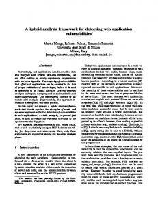
framework is handled by a full micromagnetic solver [10], which includes a spatially-dependent magnetization to accurately account for the effect of non-uniform configurations occurring during the switching process of STT-MTJs. Then, the results of micromagnetic simulations are used to generate a look-up table (LUT) based MTJ Verilog-A model, which is incorporated in the Cadence Virtuoso environment to run circuit simulations. Therefore, when compared with the conventional approach based on macrospin compact models, our full micromagnetic approach allows for more accurate prediction of the MTJ behavior. This is particularly important when innovative MTJ structures and advanced technology generations are considered, and/or when variations due to the stochastic nature of the MTJ switching need to be analyzed. Our approach is based on an a priori one-time characterization of the MTJ through full micromagnetic simulations, whereas the Verilog-A model description drastically reduces the computational effort entailed by circuit simulations. The proposed simulation framework is applied to the variability-aware analysis of hybrid MTJ/CMOS non-volatile Flip-Flops (NV-FFs) [11], whose write circuitry is implemented in two different topologies. The considered MTJ is a circular perpendicular magnetic anisotropy (PMA) STTMTJ with a diameter of 30 nm (see Fig. 1(a)). A 28-nm ultrathin body and box (UTBB) fully-depleted silicon-on-insulator (FDSOI) CMOS technology is used to ensure a superior robustness to process variability as compared to conventional bulk CMOS process [12]. The rest of the paper is structured as follows. Section II describes the adopted simulation approach. Section III reports the results of our simulations, and remarks on the results. Conclusions are provided in Section IV.
Fig. 1. (a) Sketch of the considered MTJ and (b) flowchart of the proposed simulation framework for hybrid CMOS/MTJ circuit applications.
μP→AP
μAP→P
σP→AP
σAP→P
skewP→AP
skewAP→P
1.0 0.5 0.0 2.0
2.5
3.0
3.5
|JMTJ|/Jc0
4.0
4.5
Fig. 2. Mean (μ), standard deviation (ı) and skewness (skew) of the MTJ switching delay (ts) as a function of the write current for PĺAP and APĺP transitions.
II.
A VARIATION-AWARE SIMULATION FRAMEWORK
Fig. 1(b) describes the simulation framework introduced here to perform variability-aware analysis of hybrid MTJ/CMOS circuits through Monte Carlo (MC) circuit simulations, considering the stochastic nature of the MTJ switching process and both MTJ and CMOS process variations. The micromagnetic simulation of the MTJ behavior is performed by means of a state-of-the-art solver [10], which numerically integrates the Landau-Lifshitz-Gilbert (LLG) equation considering a discretization of the FL in computational cells of 1×1×1 nm3 and the effect of the thermal field as an additional stochastic term to the deterministic effective field in each computational cell [9]. Table I reports the MTJ parameters used in micromagnetic simulations and the critical current densities computed at T=0 K for PĺAP and APĺP switching transitions, where P and AP represent the parallel and the antiparallel states of the magnetization of the FL with respect to the magnetization of the pinned layer (PL). Moreover, Fig. 2 illustrates the micromagnetic simulation results on the statistical distribution of the MTJ switching delay (ts) for both transitions, calculated at room temperature (i.e. T=300 K) on 1,000 iterations, in terms of mean value (μ), standard deviation (ı) and skewness as a function of the injected perpendicular current. As expected, all the three quantities decrease with the current. The skewness is positive since the ts distribution exhibits a right-skewed shape [6].
JMTJ=2.2×Jc0(P→AP)
8
12
2
8
1
4 0
1.0n
1.5n
2.0n
2.5n
500.00p 750.00p
ts (s)
9
Reference Normal 3 Erlang Skew Normal
Reference Normal Erlang Skew Normal
16
0 1.25n
1.00n
ts (s)
Fig. 3. Comparison between reference switching delay (ts) statistical distribution, obtained from micromagnetic simulations at T=300 K, and fitting PDFs, i.e. normal, Erlang (i.e., special case of Gamma distribution) and Skew Normal, at two different write currents for the PĺAP transition.
As shown in Fig. 1(b), the results of the micromagnetic simulations are then used to build a LUT-based MTJ Verilog-A model, which can be used in commercial circuit simulation tools. The MTJ static behavior is modeled by the critical current densities evaluated through micromagnetic simulations, and by two LUTs describing the magnetoresistance-current hysteresis loop. The developed model also incorporates MTJ process variations due to Gaussian distributed oxide thickness (tox) variations (with variability of 1%, as reported in Table I), which affect the MTJ resistance through an exponential relationship [13]. To accurately model the stochastic switching behavior of the MTJ, our simulation flow includes an additional analysis to identify an appropriate probability density function (PDF) that adequately fits the statistical distribution of ts previously obtained with micromagnetic simulations (see Fig. 1(b)). In this regard, differently from previous works where the use of a Normal [3] or a Gamma [6] function was proposed, in this work we have found that the Skew Normal PDF allows the best fitting of the outcome of micromagnetic simulations, as shown in Fig. 3. The analytical expression of the Skew Normal PDF is f ( x ; ȟ, Ȧ, Į ) =
2
ω
§ x−ȟ © Ȧ
φ¨
· § § x − ȟ ·· ¸Φ ¨Į¨ ¸¸ ¹ © © Ȧ ¹¹
(1)
where ȟ, Ȧ and Į are the location, scale and shape parameters, respectively, (x) the standard Normal PDF and ĭ(x) the corresponding cumulative distribution function (CDF). An accurate modeling of the ts statistical distribution is crucial to truly account for the MTJ stochastic switching behavior in variation-aware analysis and optimization of hybrid MTJ/CMOS circuits [3]. Indeed, the right tail of the ts distribution can strongly impact the switching probability as a 1.5
ξAP→P
ωP→AP
ωAP→P 15 αAP→P
αP→AP
1.0
10
0.5
0.0
20
ξP→AP
Shape
1.5
JMTJ=1.5×Jc0(P→AP) Units J/m A/m -J/m3 -nm nm nm eV m2 ȍ·μm2 kȍ --MA/cm2 MA/cm2
-9
2.0
Value 2.0×10⁻¹¹ 1000×103 0.03 8.0×10⁵ 0.66 30 0.85 1.0 0.4 7.07×10⁻¹⁶ 7.0 9.903 165% 1% 2.7 1.1
Location, scale (10 )
Mean (ns), std. dev. (ns), skewness
Parameter Exchange constant (A) Saturation magnetization (Ms) Gilbert damping constant (Į) Uniaxial anisotropy constant (ku) Spin polarization factor (P) MTJ diameter (dMTJ) Oxide thickness (tox) Free layer thickness (tFL) Oxide energy barrier (ijB) MTJ surface Resistance-area product (RA) MTJ resistance in P state (Rp) TMR ratio Oxide thickness variability (ı/μ)tox PĺAP critical current density (Jc0(PĺAP)) APĺP critical current density (Jc0(APĺP))
Counts (x10 )
MTJ PARAMETERS Counts (x10 )
TABLE I.
5
2.0
2.5
3.0
3.5
|JMTJ|/Jc0
4.0
4.5
0
Fig. 4. Location (ȟ), scale (Ȧ) and shape (Į) parameters of the Skew Normal PDF as a function of the write current for PĺAP and APĺP transitions.
NON-VOLATILE FLIP-FLOPS AS CASE STUDY
As case study of hybrid MTJ/CMOS circuits, NV-FFs were considered since they are well known to enable aggressive leakage reduction as compared to conventional CMOS retention latches [14]. Moreover, variations in NV-FFs can have an important impact on the timing of the considered System on Chip, both in terms of performance and robustness against variations [15]–[18]. Let us consider the write mode of NV-FFs, in which the input data is written into two MTJs with complementary states [11]. Such operation is responsible for a large energy consumption in NV-FFs, due to the required high write currents. Accordingly, in this work we analyze two write circuits used in NV-FFs [11] (see Fig. 5): a parallel circuit for two disconnected MTJs, and a serial circuit for two connected MTJs. The first circuit consists of two subcircuits, each composed of four regular threshold voltage (RVT) transistors (i.e. two nMOS and two pMOS) working at a nominal supply voltage VDD=1 V (see Fig. 5(a)). Depending on which transistors are switched on or off, each subcircuit can generate a bidirectional write current to switch the two disconnected (a)
1V
1V
(b)
V1
V2
V2
V1
1V
1.8 V
1.8 V
V1
V2
V2
V1
1V
V2
V1
V1
V2
1V RVT transistors Lmin= 30 nm Wmin= 80 nm
1.8V IO RVT transistors Lmin= 150 nm Wmin= 160 nm
Fig. 5. (a) Parallel write circuit for two disconnected MTJs and (b) serial write circuit for two series-connected MTJs.
0.9
W =120 nm 10
Counts (x10 )
9
Counts (x10 )
(a)
1.2 0.8 0.4 0.0
20
1.0n
(c)
2.0n
ts (s)
W =300 nm
0.6
0.3
20
W =120 nm
400p
(d)
600p
800p
ts (s)
W =300 nm
15
WER (%)
WER (%)
(b)
0.0
3.0n
15 10 WER = 0.1%
5 0 1.5n
2.0n
2.5n
10 5 0 500p
3.0n
WER = 0.1%
600p
700p
pulse duration (s) pulse duration (s) Fig. switching delay delay (t (tss)) statistical statistical distributions distributions Fig. 6. 6. (a) (a) and and (b) (b) PĺAP PĺAP switching calculated for for two two different different transistor transistor widths widths (W) (W) in in the the parallel parallel write write circuit circuit calculated when when applying applying both both CMOS CMOS and and MTJ MTJ variations. variations. (c) (c) and and (d) (d) Corresponding Corresponding write bit and write bit error error rate rate (WER) (WER) asas a afunction functionofofthe thewrite writepulse pulseduration width and calculation of of the the required required pulse pulse duration duration to to ensure ensure aa targeted target WER of of 0.1%. calculation WER 0.1%.
MTJs in the desired states. The second circuit uses four IO RVT transistors working at a nominal VDD=1.8 V (see Fig. 5(b)) to achieve sufficient write current above the critical one for both transitions (as required to switch the two seriesconnected MTJs in two opposite states). MC transient simulations on 10,000 runs were performed to calculate the statistical distribution of the switching delay as a function of the transistor size (i.e., channel width W), keeping the channel length L minimum (i.e. 30 nm for 1V transitors and 150 nm for 1.8V IO transistors). Transistor process and mismatch variations were accounted for by using the statistical models provided in the process design kit (PDK). As stated previously (see Section II), MTJ variations include the resistance variations and the ts stochastic variations. Accordingly, when running MC transient simulations, both the write current and the MTJs switching delay randomly vary at each MC write event. In particular, the write current is affected 4n
write delay (s)
III.
1.6
3n
(a)
parallel write circuit (1V transistors) serial write circuit (1.8V IO transistors)
(b)
parallel write circuit (1V transistors) serial write circuit (1.8V IO transistors)
2n
1n
160f
write energy (J)
function of the write pulse duration and the amplitude of applied current. For circuit simulation purposes, this behavior is modeled in our Verilog-A model by using three LUTs as inputs (see Fig. 1(b)), reporting the fitting parameters of the Skew Normal PDF as a function of the applied bias. From Fig. 4, these parameters monotonically decrease when the write current increases. This justifies the validity of our MTJ model, which is based on linear interpolation of the above three LUTs to evaluate ȟ, Ȧ and Į for a given write current and then calculate the corresponding Skew Normal distribution. Since the Skew Normal PDF is not natively available in Verilog-A, additional calculations are included in our model to incorporate the Skew Normal distribution and accordingly generate random ts samples in a close agreement with the statistical distribution extracted from micromagnetic simulations, while performing MC simulations in the Cadence environment [9]. This leads to an increase of less than 30% in terms of CPU time (for 10,000 Monte Carlo runs), as compared to the use of the statistical functions embedded in Verilog-A (e.g., Normal or Erlang PDF).
120f
80f 100
200
300
400
500
600
700
W (nm) Fig. 7. (a) Write delay and (b) corresponding write energy to ensure a targeted write bit error rate (WER) of 0.1%, as a function of the transistor channel width (W) in the two considered hybrid write circuits.
TABLE II. N° transistors
8 4
VDD (V)
SUMMARY RESULTS
L (nm)
W (nm)
write delay (ns)
Parallel write circuit 30 200 1.11 Serial write circuit 1.8 150 240 1.14 1
write energy (fJ)
84.2 91.2
by the variability of MOS transistors and the MTJ resistance. On the other hand, for a given write current, ts statistically changes due to the stochastic behavior of the two MTJs. The evaluation of the ts statistical distribution is crucial to estimate the write failure probability, as main motivation for this work. Figs. 6(a) and (b) report the PĺAP ts statistical distributions extracted for two different transistor sizes in the parallel write circuit. From the calculated distributions, we can estimate the write bit error rate (WER), which indicates the probability that the magnetization of the MTJs does not switch during the write process, under the given write pulse width (see Figs. 6(c) and (d)). According to [3], a longer write pulse increases the reliability, thus leading to a lower WER and hence a higher switching probability. In turn, a larger transistor size and thus a higher write current allows for reducing ts. After characterizing WER, the write delay is evaluated as the write pulse width required to guarantee a targeted WER, as illustrated in Figs. 6(c) and (d). Fig. 7(a) illustrates the calculated write delay to ensure a targeted WER of 0.1% (chosen for the sake of statistical robustness whereas MC transient simulations were performed on 10,000 samples) versus W of MOS transistors in the two analyzed write circuits. Note that the reported write delay at each W refers to the most critical switching transition. As expected, larger transistors lead to lower write delay. Moreover, despite of the use of 1.8V IO transistors to increase the write current, the serial write circuit exhibits a higher write delay due to the presence of two MTJs in the write path. Fig. 7(b) plots the write energy versus W, resulting from the trade-off between write delay and power. As a consequence, the write energy shows a reversed Bell shape with a minimum-energy point at W=200 nm for the parallel write circuit and at W=240 nm for the serial write circuit. Finally, Table II summarizes the results obtained in the optimization of the two circuits for ensuring reliable (with a targeted WER of 0.1%) minimum-energy write operation. We can observe that the serial write circuit achieves similar write performance as compared to the parallel circuit. This comes at costs of slightly higher energy consumption and 3X area overhead due to the use of 1.8V IO transistors. IV.
modeled through a Skew Normal distribution, which has proven to accurately fit micromagnetic simulations. To show its suitability to support variation-aware circuit design, the proposed framework has been applied to nonvolatile Flip-Flops as case study. Parallel and serial write approaches have been compared. The framework has been shown to be able to guide the design in terms of transistor sizing and statistically evaluate the bit error rate through 10,000 Monte Carlo runs. REFERENCES [1]
[2]
[3]
[4]
[5]
[6]
[7]
[8]
[9]
[10]
[11]
[12]
[13]
[14]
CONCLUSIONS
In this paper, a variation-aware simulation framework has been introduced to enable accurate simulations of hybrid MTJCMOS circuits. The framework is based on preliminary micromagnetic multi-domain simulations, which allow for removing simplistic assumptions that are traditionally made in other simulation frameworks based on macrospin approximation. The results of micromagnetic simulations are then used to calibrate the critical currents and the statistical parameters describing the stochastic switching behavior of the MTJ in a simple LUT-based Verilog-A model, thus ensuring easy integration with commercial circuit simulation environments. Stochastic variations of the MTJ switching are
[15]
[16]
[17]
[18]
S. A. Wolf, J. Lu, M. R. Stan, E. Chen, D. M. Treger, “The promise of nanomagnetics and spintronics for future logic and universal memory,” Proc. of the IEEE, vol. 98, no. 12, pp. 2155–2168, 2010. Y. Zhang et al., “Compact Modeling of Perpendicular-Anisotropy CoFeB/MgO Magnetic Tunnel Junctions,” IEEE Trans. on Electron Devices, vol. 59, no. 3, pp.819–826, 2012. Y. Zhang et al., “Electrical modeling of stochastic spin transfer torque writing in magnetic tunnel junctions for memory and logic applications,” IEEE Trans. on Magnetics, vol. 49, no. 7, pp. 4375–4378, 2013. G. D. Panagopoulos, C. Augustine, K. Roy, “Physics-based SPICE compatible compact model for simulating hybrid MTJ/CMOS circuits,” IEEE Trans. on Electron Devices, vol. 60, no. 9, pp. 2808–2814, 2013. M. Kazemi, E. Ipek, E. G. Friedman, “Adaptive Compact Magnetic Tunnel Junction Model,” IEEE Trans. on Electron Devices, vol. 61, no. 11, pp.3883–3891, 2014. A. F. Vincent et al., “Analytical Macrospin Modeling of the Stochastic Switching Time of Spin-Transfer Torque Devices,” IEEE Trans. on Electron Devices, vol. 62, no. 1, pp.164---170, 2015. J. Miltat, G. Albuquerque, A. Thiaville, C. Vouille, “Spin transfer into an inhomogeneous magnetization distribution,” Journal of Applied Physics, vol. 89, no. 11, pp. 6982–6984, 2001. M. Carpentieri et al., “Effect of the Classical Ampere Field in Micromagnetic computations of Spin Polarized Current-Driven Magnetization Processes”, Jour. of App. Phys., vol. 97, p. 10C713, 2005. R. De Rose et al., “Variability-Aware Analysis of Hybrid MTJ/CMOS Circuits by a Micromagnetic-Based Simulation Framework,” IEEE Trans. on Nanotechnology, vol. 16, no. 2, pp. 160–168, 2017. A. Giordano et al., “Semi-implicit integration scheme for Landau– Lifshitz–Gilbert-Slonczewski equation,” Journal of Applied Physics, vol. 111, pp. 07D112-1–07D112-3, 2012. T. Na, K. Ryu, J. Kim, S. H. Kang, S.-O. Jung, “A Comparative Study of STT-MTJ Based Non-Volatile Flip-Flops,” Proc. of IEEE Int. Symp. on Circuits and Systems (ISCAS), 2013, pp. 109–112. R. Taco, I. Levi, M. Lanuzza, and A. Fish, “Low Voltage Logic Circuits Exploiting Gate Level Dynamic Body Biasing in 28 nm UTBB FDSOI,” Solid-State Electronics, vol. 117, pp. 185–192, 2016. Q. K. Trinh, S. Ruocco, M. Alioto, “Voltage Scaled STT-MRAMs Towards Minimum-Energy Write Access,” IEEE Journal on Emerg. and Selec. Topics in Circuits and Systems, vol. 6, no. 3, pp. 305–318, 2016. S. Khanna et al., "An FRAM-Based Nonvolatile Logic MCU SoC Exhibiting 100% Digital State Retention at VDD= 0 V Achieving Zero Leakage With < 400-ns Wakeup Time for ULP Applications," IEEE Journal of Solid-State Circuits, vol. 49, no. 1, pp. 95-106, 2014. M. Lanuzza, R. De Rose, F. Frustaci, S. Perri, P. Corsonello, “Impact of Process Variations on Flip-Flops Energy and Timing Characteristics,” Proc. of IEEE Comp. Society Annual Symp. on VLSI, 2010, pp. 458–459. M. Lanuzza et al., “Impact of Process Variations on Pulsed Flip-Flops: Yield Improving Circuit-Level Techniques and Comparative Analysis,” Proc. of 20th International Workshop PATMOS, 2010, pp. 180-189. M. Lanuzza, R. De Rose, F. Frustaci, S. Perri, P. Corsonello, “Comparative analysis of yield optimized pulsed flip-flops,” Microelectronics Reliability, vol. 117, no. 8, pp. 1679–1689, 2012. M. Alioto, E. Consoli, G. Palumbo, “Variations in Nanometer CMOS Flip-Flops: Part I—Impact of Process Variations on Timing,” IEEE Trans.on Circuits and Systems I, vol. 62, no. 8, pp. 2035–2043, 2015.