CoM usually moves along with the swing leg without pause .... It is better to consider the friction rather than to assume it to be sufficient. ... sufficient active joints. If the robot .... pitch, roll, yaw ... we have the robot walk over 12 cylinders (Fig. 5),.
A Walking Pattern Generator for Biped Robots on Uneven Terrains Yu Zheng, Ming C. Lin, Dinesh Manocha ∗ Albertus Hendrawan Adiwahono, Chee-Meng Chew † Abstract We present a new method to generate biped walking patterns for biped robots on non-horizontal or uneven terrains. Our formulation uses a universal stability criterion that checks whether the resultant of the gravity wrench and the inertia wrench of a robot lies in the convex cone of the wrenches resulting from contacts between the robot and the environment. We present an algorithm to compute the feasible acceleration of the robot’s CoM (center of mass) and use that algorithm to generate biped walking patterns. Our approach is more general and applicable to uneven terrains as compared with prior methods based on the ZMP (zero-moment point) criterion. We highlight its applications on some benchmarks.
1. Introduction Biped walking is a key problem in the design of humanoid robots. One of the most successful stability criteria for walking robots is the ZMP criterion, which determines if the ZMP is inside the support polygon of the feet of a robot [1]. An in-depth review of the ZMP can be found in [2]. Based on the ZMP criterion, many methods to generate walking patterns have been proposed, such as [3]–[8]. However, the original ZMP criterion is primarily limited to cases where a robot walks on a horizontal flat terrain with sufficiently large friction. Several attempts have been made to extend these methods to handle terrains with slopes or stairs [9]– [12], but their applications have been limited. ∗ Y.
Zheng, M. C. Lin, and D. Manocha are with the Department of Computer Science, University of North Carolina at Chapel Hill, NC 27599 USA {yuzheng,lin,dm}@cs.unc.edu. This work was supported by ARO Contract W911NF-04-1-0088, NSF awards 0636208, 0917040 and 0904990, DARPA/RDECOM Contract WR91CRB-08-C-0137, and Intel. † A. H. Adiwahono and C.-M. Chew are with the Department of Mechanical Engineering, National University of Singapore, Singapore 117576 {albertus,chewcm}@nus.edu.sg.
1.1. Main Results We present a walking pattern generator for a biped robot to follow given foot placements on an arbitrary terrain, based on a general stability criterion [13] and a distance algorithm [14] that provides an efficient way to verify the criterion [13]. First, given any foot placement, we determine a position of the CoM such that the robot can maintain stability with the support of only one foot standing in place while the other foot shifts to the next placement. Between two such CoM positions at two adjacent foot placements (one for the left foot and the other for the right), we compute a stable trajectory of the CoM by updating the CoM status with a feasible acceleration at every time step. In order to determine the stable position and the feasible acceleration of the CoM, we use an iterative method based on a distance algorithm [14]. With these methods, the entire trajectory of the CoM that passes through all stable positions can be finally generated. The angular values of the joints of each leg are computed using inverse kinematics from the relative position of the CoM to the feet. We have implemented this algorithm, and the resulting generator tends to produce good trajectories for a robot to stably walk over several complex terrains. The rest of this paper is organized as follows: Section 2 summarizes prior work in this area. Section 3 presents an overview of our generator. Section 4 formulates the general stability criterion. Sections 5–7 introduce our methods to compute the stable CoM position and trajectory. Section 8 reports the simulation results. Section 9 concludes with possible future directions.
2. Related Work The ZMP criterion is frequently used in generating walking patterns for biped robots. Some methods generate the body motion according to a pre-determined ZMP trajectory [3], [4]. Kajita et al. [3] used the preview control of ZMP based on the cart-table model. Park and Youm [4] generalized the method by Kajita
[3], taking into account the full dynamics of a biped robot instead of the cart-table model. Another set of methods utilize the ZMP criterion to verify the stability of a robot following a planned body trajectory [5]–[8]. Some researchers extended the ZMP criterion to more general cases [9]–[12]. Kagami et al. [9] and Harada et al. [10] generalized the ZMP criterion to the case where the robot’s hands as well as feet come into contact with the environment. Sugihara et al. [11] used the ZMP on a virtual horizontal plane to verify the stability of a robot walking on a rough terrain. Huang et al. [12] modified the ZMP criterion for use over terrains with slopes or stairs. In order to overcome the limitations, a general stability criterion has been suggested instead of the ZMP criterion, which determines if the gravity [15] or the resultant of the gravity and the inertia wrench [13], [16] lies in the convex cone of feasible wrenches from contacts between a robot and its environment. Hauser et al. [17] used the static stability criterion [15] in designing a motion planner for legged robots walking on rough terrains. However, there is relatively little work on walking pattern generation based on a general dynamic stability criterion [13], [16]. One main reason is that verifying the dynamic stability of a biped robot is much more complex than the static stability or the ZMP.
3. Overview We assume that the sequence of foot placements on the ground is known, including positions and orientations, which can be pre-determined by footstep planning or motion planning algorithms [18]–[20]. Our objective is to compute a continuous trajectory of the CoM and joint angles of each leg such that the robot walks to the goal position, following the given foot placements. In this paper, we consider a biped robot walking on uneven terrains, on which the robot’s feet may have different orientations at every step and the normals at contacts on both feet are not parallel. In such cases, maintaining the robot’s stability is much more difficult than on a flat horizontal terrain. To do this, we adopt an intermittent walking strategy; that is, the CoM of the robot stays in a certain position when a leg swings and both feet remain on the ground when the CoM moves. Unlike walking on a flat horizontal terrain, where the CoM usually moves along with the swing leg without pause, alternately moving the CoM and a foot may limit the walking speed of the robot and the scope that the robot can reach. However, this facilitates the maintenance of the robot’s stability on uneven terrains. Before the swing foot lifts up, we require the CoM to reach a certain position, in which the robot can maintain its sta-
Algorithm 1. Generate the walking pattern for a task Input: initial and goal configurations of a robot; a sequence of foot placements on the ground. Output: trajectories of the CoM and all joints such that the robot walks to the goal along foot placements. 1: Adjust the robot to a starting pose (a typical motion is to squat down) 2: repeat 3: Compute the position of the CoM supported by only one foot such that the other foot can lift up and shift to its next placement 4: Move the CoM from the current position to the position computed above, while both feet still remain on the ground; calculate the joint angles on both legs using inverse kinematics 5: Move the swing leg to its next placement, while holding the CoM to its current position 6: until both feet reach their final placements 7: Adjust the robot to the goal configuration
bility with the support of only the other foot. When the CoM changes, both feet provide maximum support such that a stable trajectory of the CoM can be more easily computed than with single leg support. The walking circle is described in Algorithm 1. Computing stable CoM positions (line 3) and generating stable CoM trajectories (line 4) on uneven terrains are the main objectives of the method we present in this paper.
4. Wrenches and Stability In this section, we introduce a general stability criterion in terms of wrenches applied to a robot for use in uneven terrain walking. Henceforth, we use uppercase letters to denote sets and boldface letters to denote points, vectors, and matrices.
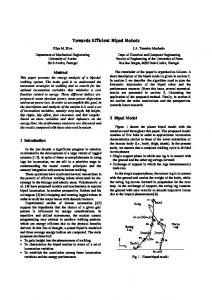
4.1. Wrenches (Forces and Moments) Fig. 1 shows a biped robot. All contacts between the robot and the environment are assumed to be hard point contacts with friction. The bottom of each foot is flat, so that the contact normal is perpendicular to the foot. If a foot makes a planar contact with the environment, the planar contact can be treated as a few point contacts on its boundary. Let Σ0 be the global coordinate frame whose z-axis is vertical. We decompose the wrenches exerted on the robot into four categories.
Wrench space
Robot space
w G can be viewed as a single point in wrench space and it is related only to the position p 0 of the CoM.
fz Wi w L
..
-wG1 wL
-wG
Mp 0
Wc
4.1.3. Linear inertia wrench. It is the wrench generated by the inertia force applied to the CoM: � � I w L = 3×3 M p¨ 0 (4) p0⊗
p02
p01 -wG2 y
Mg
fi Fi
fx
where p¨ 0 is the acceleration of the CoM. The wrench w L depends on p 0 and p¨ 0 . For a given p 0 , the direction of w L is determined by the direction of p¨ 0 , while their magnitudes are proportional to each other.
x
t
S0
Fig. 1. View of biped walking in wrench space. The friction cone Fi , the gravity force Mgg, and the linear inertia force M p¨ 0 in robot space are transformed into the convex cone Wi , the gravity wrench w G , and the linear inertia wrench w L in wrench space, respectively. The Minkowski sum of Wi for all contacts generates a convex cone Wc , which comprises all feasible wrenches that can be applied to the robot from contacts. wG As the position p 0 of the CoM moves from p 10 to p 20 , −w w1G to −w w2G . We keep −w wG + w L ∈ Wc in the moves from −w interior of Wc such that there is enough stability margin to conwG +w wL +w wA ∈ Wc ; tain the angular inertia wrench w A , i.e., −w thus the robot is dynamically stable during walking.
4.1.1. Contact wrench. The resultant wrench from all contacts with respect to the frame Σ0 can be written as � m � I 3×3 f (1) wC = ∑ r i⊗ i i=1 where r i denotes the position vector of a contact point between the robot and the environment in the frame Σ0 , f i is the contact force, and I 3×3 is the 3 × 3 identity matrix. To avoid slip at contact, f i must comply with the Coulomb friction constraint, which limits f i into a convex cone Fi specified by Fi = { f i ∈ R3 | k (II 3×3 − ni nTi ) f i k≤ µ nTi f i }
(2)
where n i is the unit normal at contact and µ is the Coulomb friction coefficient. Let Wi be the set of wrenches that can be generated by forces at contact i � �T satisfying (2); i.e., Wi = { f Ti (rr i ⊗ f i )T | f i ∈ Fi }. Let Wc = ∑m i=1 Wi , which consists of all wC given by (1) f with i ∈ Fi , i = 1, 2, . . . , m and is the set of all feasible resultant wrenches from contacts. It turns out that both Wi and Wc are convex cones. 4.1.2. Gravity wrench. The gravity and the resulting moment with respect to the origin of Σ0 are given by � � I 3×3 Mgg (3) wG = p0⊗ where p 0 is the position of the CoM in Σ0 , M is the total � �T mass of the robot, and g = 0 0 −g . The wrench
4.1.4. Angular inertia wrench. According to [13], the angular inertia wrench can be computed by � � 0 wA = ˙ (5) L where L is the angular momentum of the robot with respect to the CoM [13]: N
L=
∑ {m j (pp j − p0 ) ⊗ p˙ j + I j ω j }
(6)
j=1
where m j , p j , I j , and ω j are the mass, position, inertia tensor, and angular velocity of the j-th link of the robot, respectively.
4.2. Stability criterion A robot is statically stable if its gravity wrench can be counter-balanced by some contact forces; i.e., there exists wC ∈ Wc such that wC + w G = 0 , or equivwG ∈ Wc . The dynamic stability also takes the alently −w inertia wrenches w L and w A into account and requires wC + w G − w L − w A = 0 for some wC ∈ Wc , which is wG + w L + w A ∈ Wc . Normally, we reequivalent to −w wG or −w wG + w L + w A to be inside the interior quire −w of Wc such that there is some safety margin. The well-known stability criterion that is often used in biped walking verifies whether the ZMP lies inside the support polygon of the feet. When a robot walks on a flat horizontal terrain, it is easy to determine the ZMP and the support polygon; thus the ZMP-based stability criterion can be readily implemented. However, on non-horizontal or uneven terrains, the definition of the support polygon is unclear and the ZMP criterion is not easy to use. Here, the formulation of Wc by (1) and (2) considers the contact normal n i and the friction coefficient µ in general. Hence, the stability criterion based on Wc is generally applicable. The friction cone Fi in (2) restricts the contact force f i within a narrow region and greatly affects the stability of the robot. It is better to consider the friction rather than to assume it to be sufficient.
5. Statically Stable CoM Position Here, given the contact positions of one foot with the ground, we determine the position of the CoM such that the robot achieves static stability in that position or wG ∈ Wc . Here Wc is generated with respect to the −w single supporting foot. First we assume that the CoM is at a constant height h. Then p 0 can be written as p 0 = p¯ 0 + ρ (cos θ b 1 + sin θ b 2 )
(7)
where p¯ 0 is an arbitrary point in the horizontal plane at height h, and b 1 and b 2 are two unit orthogonal vectors that span the plane, and ρ ≥ 0 and θ ∈ [0, 2π ) are two scalar variables. We may simply choose p¯ 0 = � �T � �T � �T 0 0 h , b1 = 1 0 0 , and b2 = 0 1 0 , and discretize θ as θk = 2kπ /K, k = 0, 2, . . . , K − 1; thus the problem is to determine the domain of ρ such that wG ∈ Wc . Substituting (7) into (3) yields −w � � � � I 0 w G = 3×3 Mgg + ρ p¯ 0 ⊗ (cos θk b1 + sin θk b2 ) ⊗ Mgg = w¯ G + ρ wk . wG lies on the The above equation means that −w wk . The ray originating from −w¯ G in the direction −w intersections of the boundary of Wc with the ray give the lower and upper bounds of ρ , denoted by ρkL and wG ∈ Wc . Substituting ρkL and ρkU toρkU , such that −w gether with θk into (7) leads to two points, between which any point gives a statically stable position of the CoM. By doing this for all k = 1, 2, . . . , K, we obtain a set of points and observe: 1) the statically stable domain of the CoM is the convex hull of these points and 2) the shape of the domain or the x- and y-coordinates of these points are independent of the height h. Therefore, we do not need to recalculate the statically stable CoM domain for a different height as long as the contact positions of the feet are not changed. Nevertheless, it should be noted that the CoM position is also limited by the dimension and structure of the robot. To determine the CoM position in Algorithm 1, we may simply choose it at the center of the stable domain with respect to the single supporting foot. By doing this, wG the robot can possess a large stability margin, i.e., −w wG + w A can still be being deep inside Wc , such that −w kept in Wc during the swing of the other leg.
6. Dynamically Stable CoM Trajectory Let p 10 and p 20 be the current and next positions of the CoM computed by the above means with respect to two adjacent foot placements. Now we introduce an algorithm to generate a trajectory of the CoM from p 10 to
p 20 , which satisfies the dynamic stability criterion. According to the adopted walking strategy, the velocities of the CoM at p 10 and p 20 are zero and both feet keep touching the ground while the CoM moves from p 10 towards p 20 . Thus, Wc here is generated with respect to two feet, different from the one in Section 5. In computing the trajectory of the CoM, we first omit w A . Then the dynamic stability criterion is simwG + w L ∈ Wc . Let a and λ be the diplified to −w rection and magnitude of p¨ 0 , i.e., p¨ 0 = λ a , where k a k= 1 and λ ≥ 0. From (4), for given p 0 and p¨ 0 , � � � � Maa = λ w¯ L , where w¯ L = Ip3×3 w L = λ Ip3×3 Maa. This 0⊗ 0⊗ w w w w implies that −w G + L = −w G + λ ¯ L is a point on the wG in the direction w¯ L for any ray originating from −w λ ≥ 0. The robot can accelerate in the direction a if and only if the ray intersects Wc , provided that the robot has sufficient active joints. If the robot achieves static stawG is in bility with a safety margin, which means that −w the interior of Wc , then the ray always intersects Wc and the robot may accelerate in any direction. Since the CoM has no initial velocity and is required to move from p 10 to p 20 , the direction of acceleration can be taken to be a = (pp20 − p 10 )/ k p 20 − p 10 k, pointing from p 10 to p 20 . To determine an appropriate magnitude of acceleration, we need to compute the closest and farthest intersection points of Wc with the above ray, which represent the minimum and maximum magnitudes of feasible acceleration in that direction, namely λmin and λmax . Then the acceleration magnitude can be calculated by λ = (1 − k)λmin + kλmax , where 0 ≤ k ≤ 1. wG +w wL lies Here we choose a smaller k to ensure that −w deeply in the interior of Wc and leave a larger stability wG + w L + w A ∈ Wc eventually. Once margin so that −w the acceleration, including both a and λ , is determined, the status of the robot’s CoM is updated by p˙ 0 (t + T ) = p˙ 0 (t) + p¨ 0 (t)T
(8) 2
p 0 (t + T ) = p 0 (t) + p˙ 0 (t)T + p¨ 0 (t)T /2
(9)
where p˙ 0 is the velocity of the CoM and T is the time step. From the new status of the CoM and the positions of the feet, the new joint angles as well as the positions p j and the angular velocities ω j of the links of the robot’s legs can be calculated using inverse kinematics. Thus, we can obtain the angular inertia wrench w A and verify the entire dynamic stability criterion wG + w L + w A ∈ Wc . The update is valid if this cri−w terion is satisfied. If not so, we may choose a smaller k to reduce the acceleration of the CoM so that the inertia wrenches w L and w A can be smaller. By doing this, we attain the walking pattern for one time step. We also need to determine the timing to decelerate the robot such that the CoM can stop at the desired po-
H0
Wc v ( w 0 , W c) H1 w0 w3 Rw
w2
w1
Wc and the minimum distance from Wc to w 0 , denoted w0 ,Wc ) and d(w w0 ,Wc ), respectively. If w 0 ∈ Wc , by v (w w0 ,Wc ) = 0 and simply λmin = 0; otherwise, then d(w w0 ,Wc ) > 0 and the hyperplane H0 through v (w w0 ,Wc ) d(w w0 ,Wc ) supports Wc , as shown in with normal w 0 − v (w w 0 − v (w w0 ,Wc )) < 0, then H0 intersects Fig. 2. If w¯ T (w Rw and the intersection point can be calculated by w k+1 = w 0 + λk+1w¯
λk+1 = λk − Fig. 2. Computation of the closest and farthest intersection points of the convex cone Wc with the ray Rw , which are marked as w 2 and w 3 , respectively. The figure illustrates the iteration starting with w 0 and converging to w 2 .
sition p 20 . To do this, we try to decrease p˙ 0 to zero from the newly updated position p 0 and compare the final position p 0 of the CoM with p 20 . If p˙ 0 can be reduced to zero and the final p 0 does not exceed p 20 , then we can continue to accelerate the robot and update its status as above; otherwise, if the final p 0 exceeds p 20 , from then on we keep decelerating the robot until it reaches p 20 . To reduce p˙ 0 and decelerate the robot, we perform the above acceleration computation along the direction −aa, which is opposite to p˙ 0 . By this means, we obtain the walking pattern for one step. Then, repeating this process for all foot placements will generate a complete walking pattern for the robot.
7. Intersection of a Cone with a Ray In Sections 5 and 6, we reduced the computation of a stable CoM position and of a feasible acceleration to the problem of determining the closest and farthest intersection points of Wc with a ray. These points define the domain of a stable CoM position or feasible acceleration. In this section, we present an algorithm to compute them based on a distance computation algorithm in [14], which can efficiently calculate the nearest point on Wc to any point in wrench space and the minimum distance between them. w0 + Generally, we can express a ray as Rw = {w λ w¯ |λ ≥ 0}, where w 0 is the starting point of the ray and w¯ is a nonzero vector defining its direction. w 0 = −w¯ G wk in the CoM position computation, while and w¯ = −w wG and w¯ = −w¯ L in the acceleration compuw 0 = −w tation. To determine the closest intersection point of Wc with Rw or the minimum value of λ , we first use the algorithm in [14] to compute the nearest point on
w k ,Wc )2 d(w w¯ T (w w k − v(w wk ,Wc ))
(10) (11)
where k denotes the iteration number and starts with 0, w k − v (w wk ,Wc )) < 0, it can be proven and λ0 = 0. If w¯ T (w that w k+1 moves ahead along Rw and away from w k . Since w k+1 is on the hyperplane Hk that supports Wc , w k+1 is outside or on the boundary of Wc . In the latter case, w k+1 is just the closest intersection point of Wc with Rw . Otherwise, we repeat the iteration given by w k − v (w wk ,Wc )) < 0 holds in every (10) and (11). If w¯ T (w iteration, then w k finally converges to the closest intersection point and λk to the minimum value λmin , as dew k − v(w w k ,Wc )) ≥ 0, then we can picted in Fig. 2. If w¯ T (w conclude that Rw and Wc have no intersection. Indeed, w k − v(w w k ,Wc )) = 0, then Hk is parallel to Rw and if w¯ T (w wk − v(w wk ,Wc )) > 0, then separates Rw from Wc . If w¯ T (w Hk separates Wc and the ray starting from wk+1 along w¯ , which also implies that Rw does not intersect Wc . To compute the farthest intersection point of Wc with Rw or the maximum value λmax , we also follow the iteration given by (10) and (11). The initial point can be chosen at any point on Rw away from Wc . In evw 0 − v (w w0 ,Wc )) > 0; ery iteration it must hold that w¯ T (w otherwise Rw does not intersect Wc . If it holds all the time, then w k will converge to the farthest intersection point and λk to λmax .
8. Simulations 8.1. Simulation Setup We conduct simulations in Webots, which is a simulator that allows users to simulate dynamic behaviors of robots in a 3D virtual environment. The simulated robot is about 1.75 m high and weights 75 kg. The CoM is fixed at the hip and 0.84 m high when the robot stands upright. The robot has 30 DoFs with 7 on each leg, 6 on each arm, 2 on the waist, and 2 on the neck. Fig. 3 exhibits the detailed parameters of the robot. The friction coefficient between the robot’s feet and the ground is taken to be 0.5. First, we let the robot walk over two sets of connected slopes with different inclination angles (Fig. 4).
Parameters
Joints pitch, yaw
Mass (kg) Length (mm) Neck Head
z
x
Trunk Upper arm Lower arm CoM Hand Thigh y Shank Foot
4
220
Shoulder pitch, roll, yaw
24
580
Elbow
pitch
3.5
320
Wrist
pitch, roll
2
280
Waist
roll, yaw
1.8
160
Hip
pitch, roll, yaw
8
420
Knee
pitch
6
420
Ankle
pitch, roll pitch
2.2 310 (Height 110) Toe
Fig. 3. Parameters of the simulated robot. (a)
The parameters of the slopes are listed in Table 1. Next, we have the robot walk over 12 cylinders (Fig. 5), which are placed on the ground along a circle with a sweep angle of 60◦ . Table 2 displays their parameters. The upper surfaces of the cylinders are slopes and face along the (inward or outward) normal or the (forward or backward) tangent of the circle. TABLE 1. PARAMETERS OF S LOPES
Inclination angles Slope lengths (mm)
First slope set 20◦ −10◦ 10◦ 350 400 400
−15◦ 350
−5◦ 334
Inclination angles Slope lengths (mm)
Second slope set 15◦ −10◦ 20◦ 450 400 400
−15◦
−10◦
400
462
(b)
TABLE 2. PARAMETERS OF C YLINDERS
Fig. 4. Snapshots of the simulated walk on the (a) first and (b) second slope sets.
companied video, and on the above website. Finally the robot walks over the cylinders and turns 60◦ .
Cylinders on the right side Inclination angles 5◦ 10◦ 20◦ 5◦ Central heights (mm) 50 150 250 300
15◦ 200
5◦ 100
Cylinders on the left side Inclination angles 15◦ 10◦ 10◦ 10◦ Central heights (mm) 100 200 300 250
20◦ 150
5◦ 50
8.2. Simulation Results On the two slope sets, we keep the height of the robot’s CoM during walking to be constant: 0.72 m and 0.75 m, respectively. Fig. 6(a) and (b) shows the trajectories of the CoM generated by our algorithm and the ones recorded in the simulation. The robot walking over the slopes is displayed with snapshots in Fig. 4 and the accompanying video. Videos of higher quality can be found at http://gamma.cs.unc.edu/RobotWalk/. For the cylinder case, we allow the height of the robot’s CoM to vary according to the heights of cylinders. The trajectories of the CoM are plotted in Fig. 6(c). The robot walking is exhibited in Fig. 5, the ac-
8.3. Discussion In Fig. 6, it may be observed that the CoM in the simulation (solid line) does not exactly follows the planned trajectory (dashed line). The reason is that we treat the CoM fixed in a certain position on the robot and omit the effect of the swing leg to the CoM in planning the CoM trajectory, while the leg swing can actually cause the CoM to shift and deviate from the computed position. As shown in Fig. 6(a) and (b), the solid line starts to deviate from the dashed line where the the dashed line becomes horizontal. That is the moment when one leg starts to swing. The deviation is relatively larger in the frontal plane, so that the difference in the y-coordinate of the CoM trajectory is more evident. Nevertheless, during the planning stage, we require the wG goes deeply inCoM to reach a position such that −w side Wc , which implies that the robot achieves a large stability margin. Hence, after every deviation occurs, the robot can recover from it and continue to follow the
Fig. 5. Snapshots of the simulated walk over various cylinders.
planned trajectory. Furthermore, if the step length is not large, the deviation could be very small, as in the test of walking on cylinders (Fig. 6(c)).
9. Conclusion and Future Work The ZMP criterion is the most widely used stability criterion in legged robots. Many walking pattern generators and control algorithms have been developed based on it. The ZMP criterion achieved great success in the case where a robot walks on a flat horizontal terrain with sufficient friction, but has limited applicability in the case of uneven terrains or limited friction. In this paper, based on a general stability criterion [13] and an efficient algorithm to verify it [14], we propose a new approach to generate stable walking patterns for biped robots on uneven terrains. Its usefulness is demonstrated with simulations, where a humanoid robot walks over terrains with varying slopes. We plan to carry out more experiments on uneven or rough terrains to test our walking pattern generator. Further investigation may also be done on the integration of this walking pattern generator with efficient collision detection and fast motion planning algorithms to build a complete system for biped locomotion in complex environments.
References [1] M. Vukobratovi´c and J. Stepanenko, “On the stability of anthropomorphic systems,” Mathematical Biosciences, vol. 15 pp. 1–37, 1972. [2] M. Vukobratovi´c and B. Borovac, “Zero-moment point: thirty five years of its life,” International Journal of Humanoid Robotics, vol. 1, No. 1, pp. 157-173, 2004. [3] S. Kajita, F. Kanehiro, K. Kaneko, K. Fujiwara, K. Harada, K. Yokoi, H. Hirukawa, “Biped walking pattern generation by using preview control of zero-moment point,” in Proc. IEEE Int. Conf. Robot. Automat., Taipei, Taiwan, Sept. 2003, pp. 1620–1626. [4] J. Park and Y. Youm, “General ZMP preview control for bipedal walking,” in Proc. IEEE Int. Conf. Robot. Automat., Roma, Italy, April 2007, pp. 2682–2687. [5] Q. Huang, K. Yokoi, S. Kajita, K. Kaneko, H. Arai, N. Koyachi, K. Tanie, “Planning walking patterns for a biped robot,” IEEE Trans. Robot. Automat., vol. 17, no. 3, pp. 280–289, 2001. [6] J. Kuffner, S. Kagami, K. Nishiwaki, M. Inaba, and H. Inoue, “Dynamically-stable motion planning for humanoid robots,” Autonomous Robots, vol. 12, no.1, pp. 105–118, 2002. [7] E. S. Neo, K. Yokoi, S. Kajita, and K. Tanie, “Wholebody motion generation integrating operator’s intention and robot’s autonomy in controlling humanoid robots,” IEEE Trans. Robot., vol. 23, no. 4, pp. 763–775, 2007.
1.4 0.7 3
6
9
12 15 time (s)
18
21
24
0.1 0 −0.1 −0.2 0
27
z coordinate (m)
2.1
0 0
0.9
0.2 y coordinate (m)
x coordinate (m)
2.8
3
6
9
12 15 time (s)
18
21
24
0.85 0.8 0.75 0.7 0
27
3
6
9
12 15 time (s)
18
21
24
27
3
6
9
12 15 time (s)
18
21
24
27
(a)
1.4 0.7 3
6
9
12 15 time (s)
18
21
24
0.1 0 −0.1 −0.2 0
27
z coordinate (m)
2.1
0 0
0.9
0.2 y coordinate (m)
x coordinate (m)
2.8
3
6
9
12 15 time (s)
18
21
24
0.85 0.8 0.75 0.7 0
27
(b)
2 1 0 0
10
20
30
40
50
1.2 z coordinate (m)
1 y coordinate (m)
x coordinate (m)
3
0 −1 −2 0
10
time (s)
20
30 time (s)
40
50
1 0.8 0.6 0
10
20
30
40
50
time (s)
(c)
Fig. 6. The trajectories of the CoM on the (a) first slope set, (b) second slope set, and (c) cylinders. The dashed line represents the trajectory of the CoM generated by our method, while the solid line represents the one recorded in the simulation.
[8] F. Kanehiro, W. Suleiman, F. Lamiraux, E. Yoshida, and J.-P. Laumond, “Integrating dynamics into motion planning for humanoid robots,” in Proc. IEEE/RSJ Int. Conf. Intell. Robots Syst., Nice, France, Sept. 2008, pp. 660– 667. [9] S. Kagami, T. Kitagawa, K. Nishiwaki, T. Sugihiara, M. Inaba, and H. Inoue, “A fast dynamically equilibrated walking trajectory generation method of humanoid robot,” Auton. Robot., vol. 12, no.1, pp. 71–82, 2002. [10] K. Harada, S. Kajita, K. Kaneko, and H. Hirukawa, “ZMP analysis for arm/leg coordination,” in Proc. IEEE/RSJ Int. Conf. Intell. Robots Syst., Las Vegas, Nevada, Oct. 2003, pp. 75–81. [11] T. Sugihara, Y. Nakamura, and H. Inoue, “Realtime humanoid motion generation through ZMP manipulation based on inverted pendulum control,” in Proc. IEEE Int. Conf. Robot. Automat., Washington, DC, May 2002, pp. 1404–1409. [12] W.-W. Huang, C.-M. Chew, Y. Zheng, and G.-S. Hong, “Pattern generation for bipedal walking on slopes and stairs,” in Proc. IEEE/RAS Int. Conf. Humanoid Robots, Daejeon, Korea, Dec. 2008, pp. 205–210. [13] H. Hirukawa, S. Hattori, K. Harada, S. Kajita, K. Kaneko, F. Kanehiro, K. Fujiwara, and M. Morisawa, “A universal stability criterion of the foot contact of legged robots - Adios ZMP,” in Proc. IEEE Int. Conf. Robot. Automat., Orlando, Florida, May 2006, pp. 1976–1983. [14] Y. Zheng and C.-M. Chew, “Distance between a point and a convex cone in n-dimensional space: computation
[15]
[16]
[17]
[18]
[19]
[20]
and applications,” IEEE Trans. Robot., vol. 25, no. 6, pp. 1397–1412, 2009. T. Bretl and S. Lall, “Testing static equilibrium for legged robots,” IEEE Trans. Robot., vol. 24, no. 4, pp. 794–807, 2008. T. Saida, Y. Yokokoji, and T. Yoshikawa, “FSW (feasible solution of wrench) for multi-legged robots,” in Proc. IEEE Int. Conf. Robot. Automat., Taipei, Taiwan, Sept. 2003, pp. 3815–3820. K. Hauser, T. Bretl, J.-C. Latombe, K. Harada, and B. Wilcox, “Motion planning for legged robots on varied terrain,” Int. J. Robot.Res., vol. 27, no. 11-12, pp. 1325– 1349, 2008. J. Kuffner, K. Nishiwaki, S. Kagami, M. Inaba, and H. Inoue, “Footstep planning among obstacles for biped robots,” in Proc. IEEE/RSJ Int. Conf. Intell. Robot. Sys., Maui, HI, Oct. 2001, pp. 500–505. J. Kuffner, S. Kagami, K. Nishiwaki, M. Inaba, and H. Inoue, “Online footstep planning for humanoid robots,” in Proc. IEEE Int. Conf. Robot. Automat., Taipei, Taiwan, Sept. 2003, pp. 932–937. J. Chestnutt, J. Kuffner, K. Nishiwaki, and S. Kagami, “Planning biped navigation strategies in complex environments,” in Proc. IEEE Int. Conf. Humanoid Robots, 2003.