fault recovery will help to maximize accelerator up-time. The RF ... Data acquisition and memory block ... mezzanine card, dual ported memory (DPM), or Xilinx.
TESLA-FEL Report 2005-06
DIGITAL LOW LEVEL RF CONTROL SYSTEM FOR THE DESY TTF VUV-FEL LINAC Valeri Ayvazyan, Stefan Choroba, Alexander Matyushin, Guenter Moeller, Gevorg Petrosyan, Kay Rehlich, Stefan N. Simrock, Petr Vetrov DESY, Hamburg, Germany The algorithm for RF control is implemented in firmware of the DSP module. The control of the DSP module is done by a high level DOOCS device server. In designing the new RF software appropriate attention has been paid to provide a backward compatibility with old software that is still used.
Abstract In the RF system for the Vacuum Ultraviolet Free Electron Laser (VUV-FEL) Linac each klystron supplies RF power to up to 32 cavities. The superconducting cavities are operated in pulsed mode and high accelerating gradients close to the performance limit. The RF control of the cavity fields to the level of 10-4 for amplitude and 0.1 degree for phase however presents a significant technical challenge due to the narrow bandwidth of the cavities which results in high sensitivity to perturbations of the resonance frequency by mechanical vibrations (microphonics) and Lorenz force detuning. The VUV-FEL Linac RF control system employs a completely digital feedback system to provide flexibility in the control algorithms, precise calibration of the accelerating field vector-sum, and extensive diagnostics and exception handling capabilities. The RF control algorithm is implemented in DSP (Digital Signal Processor) firmware and DOOCS (Distributed Object Oriented Control System) servers. The RF control system design objectives are discussed. Hardware and software design of the DSP based RF control are presented.
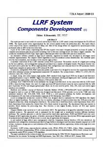
VUV-FEL LINAC RF SYSTEM The VUV-FEL Linac is designed to accelerate electrons to energy up to 1 GeV. The injector consists of a laserdriven photocathode in a 1.5-cell RF cavity operating at 1.3GHz with a peak accelerating field of 40MV/m on the cathode. The electron injector section is followed by a total of five 12.2m long accelerating modules (ACC) each containing eight 9-cell superconducting niobium cavities (figure 1). One additional accelerating module (ACC6) and 3rd harmonic accelerating structure (ACC39) will be installed in the next year. With the accelerated electrons a free electron laser will produce coherent, monochromatic light. The wavelength of the light depends on the energy of the accelerated electrons. It can be tuned between 6nm and 120nm.
INTRODUCTION The VUV-FEL Linac is the second stage of the TESLA Test Facility (TTF) [1]. A DSP system has been used for TTF phase 1 [2]. New requirements for the RF control of TTF phase 2 and in future for the VUV-FEL brought us to the idea of designing a new hardware [3]. The core part of new design is 6U-VME standard board which contains TMS320C6701 a floating-point DSP (Texas Instruments inc.) with 8 Gigalink channels. It was decided also to develop a new a multi-channel DAC board (eight 14 bit channels), and use it with existing fast ADC board [4] (eight 14 bit channels). As a communication interface between these boards and the DSP module a multi-gigabit transceiver TLK-2501 (Texas Instruments inc.) was chosen. All eight transceivers are implemented for the DSP module onboard. Additionally for the ADC and DAC boards a Gigalink Mezzanine module has been designed based on the same transceivers to interface with the DSP module. The DSP, ADC and DAC boards are implemented as a VME card. In our system the modules are controlled by SPARC VME CPUs running Solaris OS. In order to communicate to the DSP board a Solaris device driver and C++ library have been written.
Figure 1: VUV-FEL Linac RF System Diagram. First successful operation of the VUV-FEL at a wavelength of 32nm has been achieved. The accelerator provides a beam energy of 440MeV required for 32nm radiation wavelength. Since the accelerator is capable of achieving much higher beam energy such that, in a next step of the project, wavelengths around 10nm are planned. Considerable experience of RF control at high gradients close to 20MV/m with pulsed RF and pulsed beam has been gained at the VUV-FEL Linac. 1
low pass filter and the feedback algorithm applies the proportional gain to the field error. For maximum flexibility setpoint and gain parameters are updated from tables every microsecond. Additionally, a feed forward signal is added to the value of the calculated control action. It is also read from a table. These feed forward tables are optimized by measurement of the average correction signal from the feedback loop such that the average feedback signals are close to zero. The real and imaginary part of the calculated control signal are converted by separate DACs thereby applying the correction signal to the vector modulator.
RF CONTROL REQUIREMENTS The RF control requirements for amplitude and phase stability are usually derived from the desired beam parameters. It is also important to include operational issues such as the turn-on of the RF system, calibration of gradient and phase, and control of the waveguide and frequency tuners.
Amplitude and Phase Stability The requirements for amplitude and phase stability of the vector-sum a group of cavities are driven by the maximum tolerable energy spread for the VUV-FEL Linac. The goal is an rms energy spread of σE/E=10-4. The requirements for gradient and phase stability are therefore of the order of 10-4 and 0.1 degree respectively. The amplitude and phase errors to be controlled are of the order of 5% for the amplitude and 20o for the phase as a result of Lorenz force detuning and microphonics. These errors must be suppressed by a factor of more then 100 which implies that the loop gain must be adequate to meet this goal. Fortunately, the dominant source of errors is repetitive (Lorenz force and beam loading) and can be reduced by use of feedforward significantly. The requirements for the phase stability become also more severe for off-crest operation. In the case of the control of the vector-sum of several cavities driven by one klystron, the requirement for the phase calibration of the vector-sum components may become critical depending on the magnitude of microphonics.
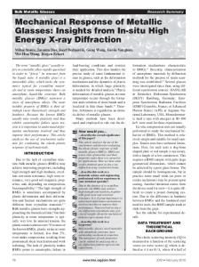
RF CONTROL HARDWARE Figure 2 shows the schematic of the RF control system at the VUV-FEL. The hardware of the digital feedback for 32 cavities consists of a DSP board with 8 Gigalink interfaces, four 8-channels ADC boards (14-bit, clocked at 1MHz) with Gigalink interface, and one 8-channel DAC board with Gigalink interface. A function generator with VME interface drives a vector-modulator which produces the local oscillator (LO) signal generated from the 1.3GHz. It switches the LO phase by 90 degrees every microsecond. Digital I/Q detectors are used for the cavity field, and the incident and reflected waves.
Operational Requirements Besides field stabilization the RF control system must provide diagnostics for the calibration of gradient and beam phase, measurement of the loop phase, cavity detuning, and control of the cavity frequency tuners. Exception handling capability must be implemented to avoid unnecessary beam loss. Features such as automated fault recovery will help to maximize accelerator up-time. The RF control must be fully functional over a wide range of operating parameters such as gradients and beam current. For efficiency reasons the RF system should provide sufficient control close to klystron saturation.
Figure 2: Schematic of the Digital RF Control System at VUV-FEL.
Multi-channel DSP Board
PRINCIPLE OF DIGITAL FEEDBACK
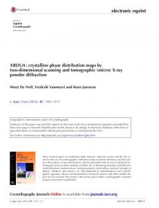
The multi-channel DSP board (figures 2,3) is a high performance floating-point digital signal processor board in VME standard with eight 1.6Gbit per second serial links (Gigalink). It is designed for fast control applications requiring high performance and flexibility. Good system adaptability is provided by the usage up to 8 high speed serial links (TLK2501). The DSP can receive/transmit simultaneously up to eight data frames from/to different source/destination, make conversion and calculation. It is powered with Texas’s floating point processor - TMS320C6701-167. The TMS320C6701 DSP uses the VelociTI modified VLIW - very long instruction world architecture, with up to eight instruction units operating in parallel. Full-speed internal program
The digital feedback controls in-phase (I) and quadrature (Q) component of the cavity field. That means the real and imaginary parts of the RF field vector are controlled instead of traditional amplitude and phase control. High frequency probe signals are used to measure the accelerating field in the individual cavities. These 1.3 GHz signals are converted to 250 kHz and sampled by the ADCs with 1 MHz rate, i.e. two subsequent data points describe I and Q component of the cavity field. The sampled field vectors of each cavity are scaled and rotated to compensate the delay in the cable length and calibrate the fields in the individual cavities. Then the sum of individual field vectors is calculated and rotated to adjust the loop phase. The vector sum is filtered by the 2
and data memories provide the bandwidth required for high data throughput. Data acquisition and memory block transfers are handled in the background by a 4-channel DMA controller. The C6701 DSP’s Host Port Interface (HPI) is usable as an expansion port, which provides an additional path for high-speed data transver from VME (up to 20 MB per second). Programming of DSP can be done via VME HPI or JTAG interfaces.
The DSP also has one SDRAM pool - 16MB on the board. SDRAM is implemented for the storage of large amounts of data and application software. This DSP module is a singlewide slave VME module (A16/D16). It should support 8 Gigalink connections (I/O interface to ADC, DAC or other DSP). A booting program is stored in the flash memory of the DSP board. At start up or after reset this program initializes the DSP internal registers and DSP Interrupt Service Table (IST). After the initialization it enters an idle loop.
Multi-channel DAC Board The DAC8 board (figure 5) is a 14-bit resolution, 8channels VME card with 40MHz clock frequency. The DAC channels are grouped in two blocks of four channels sharing two controls Xilinx’s. DAC operation is controlled by a logic implemented in Xilinx. Data to the DAC channels can be loaded either from the Gigalink mezzanine card, dual ported memory (DPM), or Xilinx data registers. Four DAC channels can be updated simultaneously using one VME command or 8 DACs by an external clock using the Gigalink interface. The Gigalink data are loaded into Xilinx registers from the attached Gigalink interface and all 8 DAC are updated simultaneously. In this mode all updates are copied into 16-words/channel circular buffer memory. This memory can be read back via the VME bus for diagnostic purpose.
Figure 3: Multi-channel DSP Board.
Rx Dat GL1 Rx Clk TLK Rx Dv 2501 Rx Err Tx Dat Rx En Rx Dat
Control Signals X i l i n x 1
SDRAM
FLASH SBSRAM
Contr
EMIF E M I F Rx Dat GL8 Rx Clk TLK Rx Dv 2501 Rx Err Tx Dat Rx En Rx Dat
X i l i n x 2
EMIF
DSP
V M E
HPI Xilinx3
JTAG
CLOCKS
+3,3V +2.5 V Power +1.9V Converter, RESET Controller
+5V GND
Figure 5: Multi-channel DAC Board. Figure 4: DSP Board Block Diagram.
Gigalink data are loaded sequentially into 8 Xilinx registers and then synchronously after short delay into the 8 DACs. In each channel internal buffer memory is used to store the last 16 words loaded into the DACs. The analog part consists of eight 14-bits DACs followed by 8 output amplifiers. Amplifiers are capable to deliver about ±3V into 50 Ohms loads. Back terminating resistor (50 Ohms) and ±8V supplies preserves amplifiers from overheating under output short-circuit conditions. One potentiometer is included into the analog path of each channel to adjust the symmetry of the output voltage. The board is a standard VME slave module. The internal registers are accessible in A24D16 mode. The board occupies 128K of the standard address space.
The Gigalink channels are grouped in two blocks by four channels sharing two controlling XilinxTM FPGAs (Field Programmable Gate Array). A third Xilinx FPGA provides basic VME-bus decoding and the interface between VME and HPI of the DSP. Besides this, the chip includes a controller for FLASH memory (1MB). This memory is used for fetching the code to be executed at system start-up and can be used by applications for nonvolatile data storage. One of the reasons to use SBSRAM is quick load/storage of data from Gigalink during normal read operation by the DSP. Then the VME Master can read these data. The special controller of SBSRAM will convert DSP read operation to write SBSRAM operation when data is read out from the Gigalink controllers. 3
the gain results in the control signal by adding the result of multiplication to the feed forward signal.
Gigalink Mezzanine Board The Gigalink Mezzanine board (figures 4,5) is a realized as small daughter board, which is used with special carrier board and provides interface between high speed serial data line and carrier board (ADC, DAC, Evaluation Board).
MO
Vector Modulator
~
Klystron
1.3 GHz
~ D A C
D A C
LO 13250 kHz
..32x.. ………..
FF
G
SP
x
-+
∑
+ Figure 6: Gigalink Mezzanine Board. DSP
R. Dat Tx_N Connector Tx_P HSSDC2
TLK 2501
Rx_N Rx_P
Rx Clk Rx Dv Controller Rx Err
Xilinx
BUS DRI VER
Tx En Tx Err Tx Dat
+3,3V Oscillator & Clock Driver
+2,5V
LDO +5V
C a r r i e r C o n n e c t o r
ADC Cavity 1
Digital ADC low pass Vector Cavity 32 filter sum
Figure 8: RF Control Algorithm Block Diagram. This control signal drives a vector modulator producing the amplitude and the phase of the klystron’s output wave. The basic formula is: ⎛ V ctrl , x ⎜ ⎜V ⎝ ctrl , y
⎞ ⎛G x ⎟ = ⎜⎜ ⎟ ⎠ ⎝ 0
0 ⎞ ⎛ V set , x ( t k ) − V frx ( t k ) ⎞ ⎛ V FF , x ( t k ) ⎞ ⎟+⎜ ⎟ ⎟•⎜ Gy ⎟⎠ ⎜⎝ V set , y ( t k ) − V fry ( t k ) ⎟⎠ ⎜⎝ V FF , y ( t k ) ⎟⎠
Where x and y are the real and the imaginary parts of the signal. ( Gx , G y ), ( Vset , x ,Vset , y ) and ( VFF , x ,VFF , y ) are
Figure 7: Gigalink Mezzanine Board Block Diagram.
corresponding individual values of gain (G), setpoint (SP) and feed forward (FF) signals at time
t k . These values
The mezzanine board includes a controller - Xilinx FPGA, a serial transceiver (TLK-2501, 1.6 Gbit per second), bus drivers, oscillator, clock driver, high speed serial data connector, and a carrier-Mezzanine connector.
are calculated by the DSP server and stored in tables. These tables can be loaded from files or directly from another application by using the DOOCS library.
RF CONTROL SOFTWARE
sum of up to 32 cavities. For faster operation the firmware was written completely in assembler language using Texas Instruments’ Code Composer Studio. That improved the operation of the firmware so significantly that the control algorithm for 32 cavities does the calculation in 1us.
( V frx ,V fry ) is produced by Kalman filter from the vector
Driver and Library The DSP board driver is written as a DDI/DDK loadable driver for Solaris which presents the DSP module as a character device. The driver controls the DSP board and allows read/write data from/to DSP board memory including its internal memory. A user process can use open (), close (), write (), read () and ioctl () system calls of this driver.
Server Programming The RF control system has been integrated into the VUVFEL control system DOOCS [5] to provide remote access to all RF data, parameters and controls. The architecture of DOOCS is based on an object oriented client/server model. The DOOCS approach defines each hardware device as a separate object and this object is represented in a network by a device server, which handles all device functions. The whole DOOCS system was designed as a set of reusable objects in shared libraries written in C++ programming language and is realized on Sun SPARC platforms and Linux running in PC environments. The libraries are used by the DOOCS servers and client applications and provide the tools to integrate the different subsystems into control system. The RF control system is naturally integrated with the VUV-FEL control
A specially written C++ library was written to simplify the interface to the driver. The library provides functions to read/write integer or floating-point data and tables from/into the board or DSP memory, load and start executable program for DSP, get information about the board and etc.
Firmware for RF Control The block diagram of the algorithm for LLRF control is shown in figure 8. After reading the input data the DSP creates the vector sum, filters it by means of a Kalman filter and calculates an error signal. Multiplying that with 4
repetitive component which is further reduced by the adaptive feed forward by about one order of magnitude, thereby exceeding the design goals significantly. The high degree of field stability achieved is mainly due to the low microphonic noise levels.
system by development of several DOOCS servers devoted to functionally self consistent part of it and the required client applications for the system management and diagnostic. The DSP server controls the DSP board hardware and contains the required functionality for managing the digital feedback subsystem. A client application can has access to the server data using DOOCS application programming interface (API). There are 3 basic subsystems in the DSP server:
CONCLUSION A digital RF control system has been developed to control the vector-sum of the accelerating field of group of superconducting cavities powered by a single klystron. The RF control system is realized as a driven feedback system and has proven that the phase and amplitude stability requirements can be meeting even in the case of control of the vector-sum of multiple cavities. The goal to provide a constant accelerating field in order to minimize the energy spread has been successfully reached. The major advantages of the system are the built-in diagnostics, configurational flexibility which are essential for the extension of up to 32 cavities driven by one klystron. The digital boards are generic and flexible enough to be usable for a variety of control and data processing applications.
• The DSP state sense and Start/Reconnect; • Load and Start a program in the DSP module; • The DSP LLRF firmware control. Start/Reconnect is activated at the start of the server and checks the state of the DSP firmware. Depending on the result, the server decides either to read the configuration and data from the DSP board or to load them from a configuration file. Load and Start allows loading an executable file into the DSP and starting it. The executable file must be in a COFF format created by Texas Instruments Code Composer Studio. The DSP LLRF firmware allows changes to the control algorithm’s tables, and can enable or disable parts of the algorithm. The operation at TTF was automated by the implementation of a DOOCS finite state machine server [6], which has access to high level applications. The start up, restart and routine operation of cryo-modules were automated. The state machine process includes loop phase measurement and correction, feedforward and feedback parameter adjustment, beam loading compensation, calibrations, and automatic fault recovery.
ACKNOWLEDGEMENTS We gratefully acknowledge the contributions from LLRF team members for their dedicated support. We also want to express our thanks to the VUV-FEL operations team for their valuable comments and helpful discussions.
REFERENCES [1] “The Conceptual Design Report for the TESLA Test Facility”, Edited by D.A. Edwards, DESY, 1995 [2] S.N. Simrock, I. Altmann, K. Rehlich, T. Schilcher, “Design of the Digital RF Control System for the TESLA Test Facility”, Proc. EPAC’96, Barcelona, Spain, p.349, 1996 [3] V.Ayvazyan, G.Petrosyan, K. Rehlich, S.N.Simrock, P.Vetrov, “RF Control System for the DESY VUVFEL Linac”, Proc. PAC’05, Knoxville, Tennessee, USA, 2005 [4] J. Andruszkow, P. Jurkiewicz, F. Tonisch, “8channel FastADC with 14 bit resolution” http://tesla.desy.de/doocs/hardware [5] G. Grygiel, O. Hensler, K. Rehlich, “DOOCS: a Distributed Object Oriented Control System on PC’s and Workstations”, ICALEPCS 97, Beijing, 1997 [6] V. Ayvazyan, K. Rehlich, S.N. Simrock, N. Sturm, “Finite State Machine Implementation to Automate RF Operation at the TESLA Test Facility”, Proc. PAC’01, Chicago, p.286, 2001 [7] H.Schlarb, V.Ayvazyan et al., “Next Generation Synchronization System for the VUV-FEL at DESY”, Proc. FEL’05, Stanford, USA
Application Software A set of generic and specially devoted programs provide the tools for the operators to control the RF system. Some of them are created based on the MATLAB, LabVIEW or ROOT, others are in-house developed DOOCS client applications. However all of them use the DOOCS API to access the data. The application software includes automated operation of the frequency tuners, calibration of the vector-sum, phasing of cavities, and adjustment of various control system parameters such as feedback gains, feed forward tables, and setpoint correction during cavity filling. Extensive diagnostics inform the operator about cavity quenches, cavities requiring manual tuning, and an excessive increase in control power.
PERFORMANCE RESULTS Currently the cavities are operating at different gradients up to 20MV/m providing a beam energy of 440MeV. The requirements of σE/E=10-4 for amplitude stability and 0.1 degree phase stability have been achieved with feedback only, the stability being verified by beam measurements [7]. The residual fluctuations are dominated by a 5