Crack arrest analysis under cyclic thermal shock for an inner-surface circumferential crack in a finite-length thick-walled cylinder
Toshiyuki MESHII a* and Katsuhiko WATANABE b a
b
Department of Mechanical Engineering, Fukui University, 3-9-1 Bunkyo, Fukui, Fukui, 910-8507, Japan
1st Division, Institute of Industrial Science, University of Tokyo, 4-6-1 Komaba, Meguro-ku, Tokyo, 153-8505, Japan *Correspondent, E-mail:
[email protected], FAX : +81-776-27-8468
ABSTRACT This paper presents a crack arrest depth analysis under cyclic thermal shock for an inner-surface circumferential crack in a finite-length thick-walled cylinder with rotation-restrained edges. The inside of the cylinder is cooled from a uniform temperature distribution. The effects of heat transfer conditions on the maximum transient SIF for the problem were investigated with systematical evaluation methods formerly developed. Then, under an assumption of a tentative threshold stress intensity range ΔKth together with the Paris law, the crack arrest depth under cyclic thermal stress was evaluated. The results suggested the existence of an upper limit for the normalized crack arrest depth, independent of the cylinder material in an engineering sense. Finally, the validity of applying ΔKmax ≤ ΔKth as a crack arrest criterion under cyclic thermal shock was confirmed by fatigue tests under mechanical loads equivalent to those induced by cyclic thermal shock. Key Words: Fracture Mechanics; Stress Intensity Factor; Crack Arrest; Thermal Shock; Threshold Intensity Range
INTRODUCTION It is interesting that, in the absence of additional cyclic external loads, crack propagation under cyclic thermal loads may not always lead to a through-thickness fracture. For example, when a cylinder of uniform temperature with an axisymmetric circumferential surface crack was cyclically cooled on the inner surface, the crack seemed not
1
to propagate over a specific normalized crack depth, regardless of the cylinder material [1]. If the crack propagation rate in such a situation fits the Paris law [2], this tendency may be explained by investigating the characteristics of the stress intensity factor (SIF) range for each cycle. As the SIF for a uniform temperature distribution is zero [3], the SIF range of interest is the maximum transient SIF itself. For this problem the SIF is affected by various factors such as the cylinder configuration, edge restraints and the cooling rate, etc. The effects of these factors on the SIF should therefore be systematically evaluated to grasp the characteristics and to reach an understanding of the crack arrest tendency. We have therefore previously proposed a method to systematically evaluate the maximum transient SIF of a circumferential crack in a finite-length thin-walled cylinder with rotation-restrained edges (Fig. 1), when the inside of the cylinder is cooled from a uniform temperature distribution [4]. The results obtained for cylinders of mean radius to wall thickness ratio Rm/W = 10.5 were as follows: i) The maximum transient SIF for the problem decreases monotonously when the crack depth becomes larger than a specific value, regardless of the heat transfer condition. ii) The SIF is strongly affected by the cylinder length. iii) The SIF for a specific finite cylinder length H = π/β is larger than that for a cylinder of infinite length. Here, β = [3(1-ν2)/(RmW)2]1/4 is a quantity used in replacing the cylindrical shell by a beam on an elastic foundation [5], where ν is Poisson’s ratio. Assuming Paris law, the fact of i) shows that a circumferential crack in a thin-walled cylinder will show arrest tendency when the thermal cycle above is repeated. In this paper the thick-walled cylinder problem similar to the experiments by Skelton and Nix [1] is dealt with. We tried to explain their experimental result analytically, i.e. that under cyclic thermal shock, a circumferential crack seems not to propagate over a specific normalized crack depth regardless of the cylinder material. For this purpose, we made a trial evaluation of the crack depth for crack arrest under cyclic thermal shock. We applied the SIF evaluation method which we had proposed for thin-walled cylinders [4] to thick-walled cylinders of Rm/W = 1, since the method based on the weight function for the crack [6] was recently shown to be applicable for cylinders of Rm/W ≥ 1 with crack depths of a/W ≤ 0.7, if we permit up to 10% difference in the SIF result compared with that obtained by finite element analysis (FEA) [7]. We assumed that the crack is located at the midpoint of the cylinder length,
2
since we know that the SIF shows its maximum for this crack location [3]. In an engineering sense, the results suggested the existence of an upper limit for the normalized crack arrest depth, independent of the cylinder material. Finally, the validity of applying ΔKmax ≤ ΔKth as a crack arrest criterion under cyclic thermal shock was confirmed by fatigue tests under mechanical loads equivalent to those induced by cyclic thermal shock.
CRACK ARREST ANALYSIS UNDER CYCLIC THERMAL SHOCK FOR AN INNER SURFACE CIRCUMFERENTIAL CRACK IN A FINITE-LENGTH THICK-WALLED CYLINDER In the following, the problem of a hollow finite-length cylinder, which is adiabatically insulated at the outside and on the inside suddenly cooled from uniform temperature at time τ = 0 sec by a coolant of an initial coolant/wall temperature difference (-2ΔT) = -100 K with a heat transfer coefficient h kW/(m2⋅K), was considered. The maximum transient SIF (Kcyl)Max was calculated by our method [4]. As for the material constants, Young’s modulus E = 198 GPa, coefficient of thermal expansion α = 16 x 10-6 /K, Poisson’s ratio ν = 0.3, coefficient of thermal conductivity Λ = 12.7 W/(m·K) and coefficient of diffusivity κ = 3.61 mm2/s were chosen, assuming austenitic steel. A cylinder length of H = π/β was chosen, because the maximum transient SIF peaked at a value close to this H [4]. For all cases, the cylinder wall thickness W was set to 10 mm.
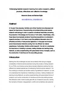
Effects of the heat transfer coefficient on the maximum transient SIF In this section, effects of the heat transfer coefficient h on (Kcyl)Max were studied by taking h at 0.465, 1.16, 11.6 and ∞ kW/(m2⋅K). As previously noted, (Kcyl)Max replaces ΔKmax in these cases. For each h, the crack length was set to a = 1, 2, 3, 4, 5, 6 and 7 mm. (Kcyl)Max normalized by KΔT defined by
K ΔT =
EαΔT πW 1 −ν
(1)
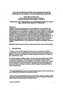
is shown in Figs.2 and 3 in normal scale and logarithmic scale, respectively. The part of dotted line in Fig.2 is linear extrapolation. Note that (Kcyl)Max/KΔT is independent of the material constants E and α, the initial condition ΔT and the wall thickness W.
3
Fig. 2 exhibits a decreasing tendency of the maximum transient SIF (Kcyl)Max for a deep crack for all heat transfer conditions. Furthermore, the gradient of the (Kcyl)Max/KΔT – a/W curve becomes steeper as h becomes larger (the peak in Fig. 2 turns out to be sharper). However, we see from Fig. 3 that the (Kcyl)Max/KΔT – a/W curves for each h are almost parallel. This indicates the fact that the increase-maximum-decrease pattern of the (Kcyl)Max/KΔT – a/W curve, which is important for the crack arrest tendency, is dominated by the structural parameters and not by h.
Crack arrest depth under cyclic thermal stress
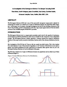
Since (Kcyl)Max showed a decreasing tendency for a deep crack under cyclic thermal shock for thick-walled cylinders, we made a trial calculation of the crack arrest depth (a/W)arrest for selected cases. Here, we assumed that the crack propagation rate fits the Paris law and that crack arrest occurs when the transient maximum SIF range ΔKmax (in our problem, = (Kcyl)Max) becomes smaller than the threshold stress intensity range ΔKth. A cylinder of Rm/W = 1 and H = π/β was chosen, and the heat transfer coefficient value h was set to h=0.465, 1.16, 11.6 and ∞ kW/(m2⋅K). Since we here explain the crack arrest phenomenon with the decrease of the transient maximum SIF range ΔKmax, we took (a/W)M (i.e. the a/W corresponding to the peak value of the maximum transient SIF) as the initial crack length. Though the specific value for austenitic steel is not known, ΔKth = 3 MPam1/2 was assumed here, because the value for a variety of steels is known to be about 3 [8]. Otherwise, the configuration, the material constants and the initial conditions are the same as those given at the beginning. The results are shown in Fig. 4. Here the heat transfer coefficients are normalized in the form of Biot No. = h/WΛ. Note that the minimum (a/W)arrest for each curve corresponds to (a/W)M in Fig. 2. The results corresponding to a linear extrapolation in Fig.2 are shown by dotted lines for the range of a/W > 0.7. For example, when h = 1.16 kW/(m2⋅K) (Biot No. = 0.92) and 2ΔT = 150 K, KΔT /ΔKth = 20 and the normalized crack arrest depth can be obtained as (a/W)arrest = 0.54 from Fig.4. If 2ΔT is smaller than 71 K (KΔT /ΔKth = 9.5), then crack will not propagate at all (this means that ΔKmax < ΔKth is satisfied from the beginning). It is very interesting that in case that h is larger than 11.6 kW/(m2⋅K) (Biot No. h/WΛ= 9.17), (a/W)arrest is hardly affected.
4
Discussion on the crack arrest depth under cyclic thermal stress
Keeping in mind the fact that (Kcyl)Max = ΔKmax is proportional to KΔT [4], the results in Fig. 4 remain valid for cylinders with different W and other values of E, α, ΔT and ΔKth, as long as the material constants ν, Λ and κ are held constant. In the case of h = ∞, the results in Fig. 4 also become independent of Λ and κ, since they affect Kcyl only through the normalized time (i. e. Fourier No.) [4]. We see from Fig. 4 that the plots of (a/W)arrest converge to a limiting value with increasing KΔT /ΔKth. When we remember the foregoing discussion in the case of h = ∞, we can deduce that the limiting value of (a/W)arrest is independent of the material constants E, α, ΔT, ΔKth, Λ and κ. Thus the only remaining material constant is
ν.
However, when we varied ν from 0 to 0.5 and recalculated (a/W)arrest in Fig. 4, the change in (a/W)arrest was less than 10%. In addition, the (a/W)arrest - KΔT /ΔKth characteristics did not change and a limiting value of (a/W)arrest did exist. We therefore think that, in an engineering sense, the limiting value of (a/W)arrest is independent of material properties, as far as the material is a metal. This phenomenon is explained by the fact that the linear extrapolation part of the curves in Fig. 2 seems to intersect near (a/W, (Kcyl)Max/KΔT ) = ( 0.83, 0). In the evaluation of Fig. 4, a crack length of a/W ≥ (a/W)M was assumed so that (Kcyl)Max (=ΔKmax) decreases monotonously with a/W. On the other hand, in the range of a/W < (a/W)M, there exists a possibility that from the beginning ΔKmax is less than ΔKth. This means that under Paris law, the initial crack will not propagate at all, although ΔKmax increases once the crack starts to propagate. However, in the short crack region there is a possibility for the initial crack to start to propagate, even if ΔKmax < ΔKth [9].
EXPERIMENTS The crack arrest analysis in the previous section was based on the criterion ΔKmax ≤ ΔKth. The limiting value of (a/W)arrest corresponds to ΔKth = 0 and the existence of this limiting value suggests the fatigue crack to be arrested even in this extreme case. However in most cases, cracks do not propagate up to the limiting value and the predicted (a/W)arrest depends on the actual value of ΔKth. The material resistance ΔKth is usually evaluated as the ΔK value that corresponds to da/dN = 10-7 mm/cycle
5
using measured da/dN - ΔK data [10], whose ΔK is controlled by the following equation. ΔK = ΔK 0 e C ( a − a
0)
(2)
where ΔK0 is the ΔK for the initial crack length a0 and C = (d(ΔK)/da)/ΔK = constant is the normalized ΔK -gradient. On the other hand, C for thermal shock equivalent (TSE) loads is not constant. We can see this for example from the curve named Original in Fig. 5 (this Original corresponds basically to the case of Biot No. = ∞ in Fig. 2 and was scaled so as to satisfy ΔK = 3 MPam1/2 (ΔKth of many steels) at a/W = 0.7). Since there is no data to explain the effect of such a C history on the threshold stress intensity range (TSIR), we therefore measured TSIR data for TSE loads corresponding to Fig. 2.
Experimental setup
We basically measured the TSIR for TSE loads according to ASTM E647 [10], with ΔK at da/dN = 10-7 mm/cycle. A standard CT specimen of width W = 50 mm and thickness B = 12.5 mm was machined to have a notch of 15 mm. The specimen was precracked by an additional 3 mm so that a0 ≈ 18mm. The tests were conducted for SS400 steel (Tables 1 and 2) under Kmax = 18 MPam1/2 = constant and for 3 different loading conditions (Fig. 5). We chose the Kmax constant method [11] expecting to obtain the intrinsic TSIR. We rescaled the horizontal axis in Fig. 2 to approximately realize the C - a characteristics of the Original case (Fig. 5) and obtained load curve 1 in Fig. 6. The expected difference due to the accuracy of the approximation was roughly checked by tests according to load curve 2 in Figs. 5 and 6. Curve 3 shows the standard ΔKth test load. All tests were conducted at room temperature. The results are shown in Fig. 7.
Experimental results
The maximum difference between the intended ΔK (Fig. 6) and the measured ΔK was 5.4 %. We see from Fig. 7 that ΔKth (TSIR for load 3) is smaller than the TSIR for TSE loads 1 and 2, although the differences in these three are small. We can at least say that the TSIR does not decrease by changing the load history in Figs. 5 and 6 from load curve 3 to 1 or 2, and thus our approach for judging fatigue crack arrest under TSE loads by ΔKth cannot be
6
very erroneous.
Discussion of the experimental results
We see from Fig. 7 that the TSIR differences for the three loads are small. On the other hand, the differences in C for the three loads are large. In case C is constant, the TSIR is reported to increase with larger absolute values of C since “by decreasing ΔK too quickly, the crack may arrest prematurely, owing to the inability of the crack to grow through the plastic zone created by the prior loading cycles” [12]. Though the C for TSE loads 1 and 2 are not constant, Kmax and thus the crack tip plastic zone size ry are kept constant throughout the test. Therefore, considering the fact that the absolute C for long cracks increase in the sequence of load 3, 1 and 2, the TSIR will also increase in this sequence. The results in Fig. 7 do not contradict the predicted tendency, although the differences are small. We conclude that the change rate of C hardly affects the TSIR in case Kmax is kept constant. Fatigue crack propagation tests under TSE loads were planned to realize the ΔK –a characteristics of a circumferential crack under cyclic thermal shock (paying attention to C - a characteristics) under Kmax = constant condition. We selected the Kmax = constant test method expecting to obtain the intrinsic TSIR, because the method eliminates crack closure near to the threshold. If we consider the fact that the minimum values of the actual TSE loads are zero, crack closure will apparently increase the ΔKth. Thus we concluded that the fatigue crack arrest criteria of ΔKmax ≤ ΔKth is a conservative evaluation.
CONCLUSIONS The crack arrest depth under cyclic thermal shock for an inner-surface circumferential crack in a finite-length thick-walled cylinder was studied by applying a formerly developed SIF evaluation method to the problem. First we systematically investigated the effects of the heat transfer condition on the maximum transient SIF of the crack under such transient temperature distributions for thick-walled cylinders. Then, assuming a tentative value for the threshold stress intensity range ΔKth and the Paris law, the crack depth for crack arrest under cyclic thermal shock was evaluated. We tried it for a cylinder of Rm/W = 1 and H = π/β under various heat transfer conditions. Finally, we
7
conducted crack propagation tests under equivalent thermal shock loads to confirm the validity of the criterion ΔKmax ≤ ΔKth for fatigue crack arrest under these loads. The results obtained are as follows: I) The maximum transient SIF for the problem shows a decreasing tendency of the SIF for a deep crack, regardless of the heat transfer condition. This tendency is dominated by the structural parameters. II) It seems that in an engineering sense, there exists a limiting value of (a/W)arrest independent of the cylinder materials. This suggests that circumferential cracks inside a hollow cylinder of Rm/W = 1 under cyclic thermal stresses will be arrested regardless of the heat transfer conditions or material properties. This phenomenon is explained by the fact that the increase-maximum-decrease pattern of the (Kcyl)Max/KΔT – a/W curve is dominated by structural parameters and not by heat transfer conditions nor by material properties. III) The threshold stress intensity range corresponding to a thermal shock equivalent load was approximately equal to the intrinsic ΔKth. The validity of applying ΔKmax ≤ ΔKth as a crack arrest criterion under cyclic thermal shock was confirmed. Acknowledgement
Part of this research was supported by a grant from the Japan Society for the Promotion of Science, contract no. General C (2) 12650078. References
[1] R. P. Skelton, K. J. Nix, Crack Growth Behaviour in Austenitic and Ferritic Steels during Thermal Quenching from 550 oC, High Temperature Technology, vol. 5, pp. 3-12, 1987. [2] P. C. Paris and F. Erdogan, A Critical Analysis of Crack Propagation Laws, Trans. ASME D, vol. 85, pp. 528-534, 1963. [3] T. Meshii and K. Watanabe, Closed Form Stress Intensity Factor for an Arbitrarily Located Inner-Surface Circumferential Crack in an Edge-Restraint Cylinder under Linear Radial Temperature Distribution, Engineering Fracture Mechanics, vol. 60, pp. 519-527, 1998. [4] T. Meshii and K. Watanabe, Maximum Stress Intensity Factor for a Circumferential Crack in a Finite Length Thin-Walled Cylinder under Transient Radial Temperature Distribution, Engineering Fracture Mechanics, vol. 63,
8
pp. 23-38, 1999. [5] S. P. Timoshenko, Strength of Materials. Part II, 2nd ed, Van Nostrand, Princeton, 1934. [6] T. Meshii and K. Watanabe, Stress Intensity Factor Evaluation of a Circumferential Crack in a Finite Length Thin-Walled Cylinder for Arbitrarily Distributed Stress on Crack Surface by Weight Function, Nuclear Engineering and Design, vol. 206, pp. 13-20, 2001. [7] T. Meshii and K. Watanabe, Stress Intensity Factor for a Circumferential Crack in a Finite-Length Thin to Thick-Walled Cylinder under an Arbitrary Biquadratic Stress Distribution on the Crack Surfaces, Engineering Fracture Mechanics, vol. 68, pp. 975-986, 2001. [8] D. Taylor, Fatigue Thresholds, p. 43, Butterworth & Co, London, 1989. [9] R. Hertzberg, W. A. Herman, T. Clark and R. Jaccard, Simulation of Short Crack and Other Low Closure Loading Conditions Utilizing Constant Kmax ΔK-Decreasing Fatigue Crack Growth Procedures, in J. M. Larsen and J. E. Allison (eds.) Small-Crack Test Methods, ASTM STP 1149, pp. 197-220, American Society for Testing Materials, Philadelphia, 1992. [10] ASTM-E647-95a, Standard Test Method for Measurement of Fatigue Crack Growth Rates, in Annual Book of Standards, vol. 03.01, p. 577-613, American Society for Testing Materials, Philadelphia, 1999.. [11] H. Döker, V. Bachmann and G. Marci, A Comparison of Different Methods of Determination of the Threshold for Fatigue Crack Propagation, in J. Bäcklund, A. F. Blom and C. J. Beevers (eds), Fatigue Thresholds, vol. 1, p. 45-58, EMAS, Warley, 1982. [12] T. R. Clark, W. A. Herman, R. Hertzberg and J. Jaccard, The Influence of the K Gradient and Kcmax Level on Fatigue Response during the Threshold Testing of Van 80 Steel and Astroloy, International Journal of Fatigue, vol. 19, pp. 177-182, 1997.
9
List of figures and tables Fig. 1. Circumferentially cracked cylinder under arbitrary radial temperature distribution. Fig. 2. Effect of heat transfer coefficient h on maximum transient SIF (Rm/W = 1, H = π/β = 24.4 mm, ν = 0.3, Λ = 12.7 W/(m·K) and κ = 3.61 mm2/s). Fig. 3. Fig. 2 in double logarithmic scale. Fig. 4. Crack arrest depth (Rm/W= 1, H = π/β = 24.4 mm, ν = 0.3, Λ = 12.7 W/(m·K), κ = 3.61 mm2/s). Fig. 5. Comparison of C-a relation for tests. Fig. 6. Comparison of ΔK-a relation for tests. Fig. 7. Result of thermal shock equivalent ΔK test and ΔKth test. Table 1 Chemical composition of test material (SS400 steel) in wt. % Table 2 Mechanical properties of test material (SS400)
10
T(η)
H/2
x a Ri
W
H/2
Rm
η
Fig. 1. Circumferentially cracked cylinder under arbitrary radial temperature distribution.
0.5
(a /W ) M = 0.13 Biot No. hW/ Λ =
0.4
(K cyl) Max /K
T
◆ ∞ ■ 9.17 ▲ 0.92 ● 0.37
0.3 (a /W ) M = 0.15
0.2
0.1
0 0
0.1
0.2
0.3
0.4
0.5
0.6
0.7
0.8
0.9
1
a/W Fig. 2. Effect of heat transfer coefficient h on maximum transient SIF (Rm/W = 1, H = π/β = 24.4 mm, ν = 0.3, Λ = 12.7 W/(m·K) and κ = 3.61 mm2/s).
11
(K cyl ) Max /K Δ T
1
Biot No. hW / Λ =
0.1
◆ ∞ ■ 9.17 ▲ 0.92 ● 0.37
0.01 0.01
0.1
1
a/W
Fig. 3. Fig. 2 in double logarithmic scale.
1 0.9 0.8
(a/W )arrest
0.7 0.6 Biot No. hW/ Λ =
0.5 0.4
◆ ∞ ■ 9.17 ▲ 0.92 ● 0.37
(20, 0.54)
0.3 0.2 0.1 0
(9.5, 0.15)
0
10
20
30
40
50 60 KΔT /ΔKth
70
80
90 100
Fig. 4. Crack arrest depth (Rm/W= 1, H = π/β = 24.4 mm, ν = 0.3, Λ = 12.7 W/(m·K), κ = 3.61 mm2/s).
12
0.6 0.4
C mm -1
0.2 0.0
Original
-0.2
Δ K th test
③ ①
-0.4
Thermal shock equivalent test
-0.6 -0.8 -1.0 0
5
10
18
15
②
20
24
25
a mm Fig. 5. Comparison of C-a relation for tests.
15
Δ K MPam 1/2
①
Thermal shock equivalent test
10 ② ③ Δ K th test
5 3 0
18
19
20
21
22
23
a mm Fig. 6. Comparison of ΔK-a relation for tests.
13
24
25
10 -6
da/dN mm/cycle
Thermal shock equivalent test ① Thermal shock equivalent test ② Δ K th test
10 -7
1
③
③2.8 ① 3.2 ② 3.4
10
1/2
Δ K MPam
Fig. 7. Result of thermal shock equivalent ΔK test and ΔKth test.
Table 1 Chemical composition of test material (SS400 steel) in wt. %
C 0.12
Si
Mn
P
0.23
0.57
0.014
S 0.015
Table 2 Mechanical properties of test material (SS400)
Yield Point MPa 274
Tensile Strength MPa 435
14
Elongation % 36
Fe Bal.