SUGGESTION FOR A UNIFIED PERFORMANCE ASSESSMENT CRITERION OF SPACECRAFT PROPELLANTS W. BOUAJILAI and J. RICCIUSII DLR Lampoldshausen – Institute of Space Propulsion I II
[email protected] [email protected]
Abstract Propellant performance is usually assessed through the comparison of either the specific impulse 𝐼𝑠𝑝 or the specific impulse density 𝐼𝑠𝑝,𝑑 of different propellants. However, each of these performance parameters could result in a different ranking of the propellants performances which makes it harder to make a suitable choice without having in mind an actual application. In order to overcome this problem, a unified performance assessment criterion based on both of these usual performance parameters is suggested in the present paper. The relevance of this unified performance assessment criterion has been shown over a wide range of propellants (mono and bi-propellants) for several in-service spacecrafts.
Introduction In the aim to lower the cost of access to space, alternative “green propellants” are investigated as possible substitutes to the well established toxic propellants as hydrazine for monopropellant spacecrafts or mono-methylhydrazine (MMH) in combination with dinitrogen-tetroxide (NTO) for bipropellant spacecrafts. Handling toxic propellants is a costly procedure. The lower toxicity of “green propellants” is expected to result in considerable cost saving achievements by offering simple and safe handling and allowing other work to proceed in parallel with propellant handling with reduced safety precautions. Moreover, the production and operational costs of these green propellants are expected to be lower. In order to be competitive, the “green propellants” must achieve an acceptable performance in comparison to the performance of the toxic propellants they are intended to substitute. The performance parameter suggested in the current publication is based on a weighted linear
combination of both the specific impulse and the specific impulse density.
Definitions Specific impulse The specific impulse 𝐼𝑠𝑝 is a way to describe the efficiency of a propellant. It is defined as the total impulse delivered per unit mass of propellant: 𝐼𝑠𝑝 =
𝑡 0
𝐹𝑑𝑡
𝑔 𝑚𝑑𝑡
=
𝐶𝑒 𝑔 Equation 1
where F is the thrust of the considered engine, 𝑚 is the propellant mass flow rate, Ce is the equivalent exhaust velocity and g is the Earth’s gravitational constant at sea level. The higher the specific impulse, the less propellant mass is needed to gain a given amount of momentum. It is therefore an important parameter to classify a substance and its suitability as a propellant. Specific impulse density In addition to describe the performance of a propellant, the specific impulse density 𝐼𝑠𝑝 ,𝑑 also considers the impact of a propellant on the propulsion system in terms of tank volume and system weight. A higher specific impulse density results in a lower system volume and weight. The specific impulse density is given by [1]: 𝐼𝑠𝑝 ,𝑑 =
𝜌 𝐼 𝜌𝑤 𝑠𝑝 Equation 2
where w, the density of water, is used as a convenient reference in order to keep the specific impulse density measured in seconds and is related to the density of the considered propellant(s):
For monopropellants, corresponds to the density of the considered monopropellant p For bipropellants, corresponds to the average specific density av which for a particular mixture ratio R is defined as [1] 𝜌𝑎𝑣 =
where K is the shell to tank mass correction factor, m the density of the tank material, u the ultimate strength of the tank material, Vt the tank volume and pb the burst pressure of the tank. The required volume of the tank to store the amount Mp of propellant of a density of p is determined by Equation 7
𝜌𝑜𝑥 𝜌𝑓𝑢𝑒𝑙 1 + 𝑅 𝜌𝑜𝑥 + 𝜌𝑓𝑢𝑒𝑙 𝑅
𝑉𝑡 =
𝑀𝑝 𝜌𝑝
Equation 3
with ox the oxidizer density, fuel the fuel density and R defined as [1] 𝑅=
𝑚𝑜𝑥𝑖𝑑𝑖𝑧𝑒𝑟 𝑚𝑓𝑢𝑒𝑙 Equation 4
Relationship between change in velocity, specific impulse and propellants densities As space missions are usually driven by the velocity change, the change in velocity will be considered as a key parameter in the currently presented work. Basic equations The change in velocity v is defined using the Tsiolkovsky’s Equation 5 ∆𝑣 = 𝑔𝐼𝑠𝑝 𝑙𝑛
Equation 7
Change in velocity as a function of the spacecraft parameters For bipropellant spacecrafts, the couple of propellants (oxidizer and fuel) are stored in two different tanks. Both tanks are assumed to have identical shapes and made from identical materials which show identical burst pressures. Defining 𝑀𝑖 = 𝑀𝑠𝑦𝑠 + 𝑀𝑝 + 𝑀𝑡𝑎𝑛𝑘 (𝑠) and considering Equation 7 and Equation 6 in Equation 5 results in the expression of v in Equation 8. This expression is valid for both monopropellants and bipropellants in case the density the average specific density av is considered for bipropellants and the propellant density p is considered for monopropellants: ∆𝑣 = 𝑔𝐼𝑠𝑝 𝑙𝑛
𝑀𝑖 𝑀𝑖 − 𝑀𝑝
Equation 8 Equation 5
In this equation Isp is the specific impulse, Mi the initial mass or wet mass or total mass of the spacecraft before any propellant is used up and Mp the propellant mass. Based on the shell mass Mshell, an empirical formula is used to define for a fully metallic tank, the tank assembly mass, i.e. the mass of the shell and all the appendages directly related to the tank 𝑀𝑡𝑎𝑛𝑘 = 𝐾 𝛼
𝐾′ + 𝜌 𝐾 ′ + 𝑀′𝜌
𝜌𝑚 𝑉𝑝 𝜎𝑢 𝑡 𝑏
𝜌𝑚 𝑝 𝜎𝑢 𝑏 𝑀𝑖 = 1 − 𝑀𝑝 𝑀𝑖 1 + 𝐾′ 𝜌 𝐾 ′ = 𝐾𝛼
𝑀′ = 𝑀𝑠𝑦𝑠
𝛼 = 3 2 𝑓𝑜𝑟 𝑎 𝑠𝑝𝑒𝑟𝑖𝑐𝑎𝑙 𝑡𝑎𝑛𝑘 𝛼 = 2 𝑓𝑜𝑟 𝑎 𝑐𝑦𝑙𝑖𝑛𝑑𝑟𝑖𝑐𝑎𝑙 𝑡𝑎𝑛𝑘
Expressing the change in velocity as a function of the specific impulse and the specific impulse density Dependence of v on both Isp and Isp,d Expressing the density as a function of the specific impulse density Isp,d using Equation 2, Equation 8 becomes
𝑀𝑠 𝑒𝑙𝑙
Equation 6
𝛼 = 3 2 𝑓𝑜𝑟 𝑎 𝑠𝑝𝑒𝑟𝑖𝑐𝑎𝑙 𝑡𝑎𝑛𝑘 𝛼 = 2 𝑓𝑜𝑟 𝑎 𝑐𝑦𝑙𝑖𝑛𝑑𝑟𝑖𝑐𝑎𝑙 𝑡𝑎𝑛𝑘
∆𝑣 = 𝑔𝐼𝑠𝑝 𝑙𝑛 1 +
1 − 𝑀′ 𝜌𝑤 𝐼𝑠𝑝 ,𝑑 𝐾 ′ 𝐼𝑠𝑝 + 𝑀′𝜌𝑤 𝐼𝑠𝑝 ,𝑑
Considering the variable substitutions above, Equation 9 becomes
Equation 9
∆𝑣 = 𝑔𝐼𝑠𝑝 ,𝑟𝑒𝑓 𝑋1 ∙ 𝑙𝑛 1
with w, the water density (for the follow-on analyses assumed to be 1000 kg/m3). Equation 9 illustrates a direct dependency of the change in velocity v on both, the specific impulse Isp and the specific impulse density Isp,d. In case the characteristics of a spacecraft are known, Equation 9 could be used for the ranking of the propellants relative to their performance using both the specific impulse and the specific impulse density and considering the change in velocity as the ranking criterion. The larger the velocity change, the more efficient the propellant. However, the velocity change defined in Equation 9 could not be used as a universal criterion in the ranking of propellants in the framework of basic research projects such as GRASP [2, 3] as the spacecraft´s characteristics are not known at this stage. Moreover, the importance (or weights) of the specific impulse and the specific impulse density could not be easily identified through this equation. Therefore, a simplified relationship between the change in velocity and both performance parameters resulting in an approximation of v is investigated to overcome these two issues. Approximation of v as a linear combination of Isp and Isp,d Two methods have been applied in order to define a simple relationship between v, Isp and Isp,d and to evaluate the accuracy of the obtained relationship:
Taylor Series method Equation solution method
Taylor Series method Based on the definition of the Taylor Series method, a propellant (for monopropellant) or a couple of propellants (for bipropellants) is considered as a development point (or reference). For this purpose, the following variable substitutions are proposed: 𝑋1 = 𝐼𝑠𝑝 ,𝑝𝑟𝑜𝑝𝑒𝑙𝑙𝑎𝑛𝑡 𝑋2 = 𝐼𝑠𝑝 ,𝑑,𝑝𝑟𝑜𝑝𝑒𝑙𝑙𝑎𝑛𝑡
𝐼𝑠𝑝 ,𝑟𝑒𝑓𝑒𝑟𝑒𝑛𝑐𝑒 𝐼𝑠𝑝 ,𝑑,𝑟𝑒𝑓𝑒𝑟𝑒𝑛𝑐𝑒
+
1 − 𝑀′ 𝜌𝑤 𝐼𝑠𝑝 ,𝑑,𝑟𝑒𝑓 𝑋2 + 𝑀′𝜌𝑤 𝐼𝑠𝑝 ,𝑑,𝑟𝑒𝑓 𝑋2
𝐾 ′ 𝐼𝑠𝑝 ,𝑟𝑒𝑓 𝑋1
Equation 10
Assuming 𝑋 = 𝑋1 ; 𝑋2 and working near the development point 𝑋𝑟𝑒𝑓 = 1; 1 corresponding to the reference propellant, v could be approximated using the Taylor Series approach by the following expression: Δ𝑣 𝑋
∗
𝜕Δ𝑣 𝑋 −1 𝜕𝑋1 𝑋 =1 1 1 𝜕Δ𝑣 + 𝑋 −1 𝜕𝑋2 𝑋 =1 2 2 + 𝑜 𝑋1 − 1 2 + 𝑋2 − 1
= Δ𝑣 𝑋𝑟𝑒𝑓 +
2
Equation 11
with the partial derivatives defined as 𝜕∆𝑣 𝜕𝑋1
1 − 𝑀′ 𝜌𝑤 𝐼𝑠𝑝 ,𝑑,𝑟𝑒𝑓 𝑋2 𝐾 ′ 𝐼𝑠𝑝 ,𝑟𝑒𝑓 𝑋1 + 𝑀′𝜌𝑤 𝐼𝑠𝑝 ,𝑑,𝑟𝑒𝑓 𝑋2 𝐾′𝐼𝑠𝑝 ,𝑟𝑒𝑓 𝜌𝑤 𝐼𝑠𝑝 ,𝑑,𝑟𝑒𝑓
= 𝑔𝐼𝑠𝑝 ,𝑟𝑒𝑓 𝑙𝑛 1 + + 𝑋1 ∙
𝐾 ′ 𝐼𝑠𝑝 ,𝑟𝑒𝑓 𝑋1 + 𝑀′𝜌𝑤 𝐼𝑠𝑝 ,𝑑,𝑟𝑒𝑓 𝑋2 𝑀′ − 1 𝑋2
𝐾 ′ 𝐼𝑠𝑝 ,𝑟𝑒𝑓 𝑋1 + 𝜌𝑤 𝐼𝑠𝑝 ,𝑑,𝑟𝑒𝑓 𝑋2 Equation 12
𝐾′𝐼𝑠𝑝 ,𝑟𝑒𝑓 𝜌𝑤 𝐼𝑠𝑝 ,𝑑,𝑟𝑒𝑓 𝜕∆𝑣 = 𝑔𝐼𝑠𝑝 ,𝑟𝑒𝑓 𝑋1 ′ 𝜕𝑋2 𝐾 𝐼𝑠𝑝 ,𝑟𝑒𝑓 𝑋1 + 𝑀′𝜌𝑤 𝐼𝑠𝑝 ,𝑑,𝑟𝑒𝑓 𝑋2 1 − 𝑀′ 𝑋1 ∙ ′ 𝐾 𝐼𝑠𝑝 ,𝑟𝑒𝑓 𝑋1 + 𝜌𝑤 𝐼𝑠𝑝 ,𝑑,𝑟𝑒𝑓 𝑋2 Equation 13
Both of these partial derivative expressions shown in Equation 12 and Equation 13 are valid only in case the M’ ratio is independent of the propellant’s specific impulse density. This assumption will be verified later in this paper. Equation solution method In order to define a linear relationship between v and both Isp and Isp,d, two cases have been considered as shown by Equation 14 and Equation 15.
Weighting factor approach Δ𝑣 ∗∗ = 𝑎𝐼𝑠𝑝 + 𝑏𝐼𝑠𝑝 ,𝑑 Equation 14
Linear relationship approach Δ𝑣 ∗∗∗ = 𝑐𝐼𝑠𝑝 + 𝑑𝐼𝑠𝑝 ,𝑑 + 𝑒 Equation 15
The coefficients a, b, c, d, and e are assumed to be constants. Each set of coefficients has been determined by considering several monopropellants or couples of bipropellants. The determination of the set of coefficients is based on solving a system of equations for every monopropellant or couple of bipropellants while taking into account a unique monopropellant or couple of bipropellants as a reference. For monopropellants, hydrazine will be considered as reference due to its wide use as a monopropellant in spacecraft propulsion. For bipropellants, nitrogen tetroxide (NTO) / monomethyl-hydrazine (MMH) is considered as a reference for the oxidizer/fuel combination.
Determination of the variables the change of velocity is dependent on In this section, the determination of the coefficient sets of Equation 11, Equation 14 and Equation 15 using the performance parameters for various monopropellants or couples of bipropellants is shown. In a first step, the change in velocity value v is determined using the characteristics of a single spacecraft. In a second step, the accuracy of these methods is investigated by comparing the approximated values of the change in velocity v*(*(*)) to its exact values v over a wide range of propellants and for several spacecrafts. Considered parameters Two sets of parameters will be considered separately. The first set of parameters is related to the spacecraft: tank(s) parameters, spacecraft initial mass and the carried propellant mass. These parameters will be used to calculate the exact value of the change in velocity v. The second set of parameters contains the propellant(s) performance parameters such as the specific impulse Isp and the specific impulse
density Isp,d. These parameters will be used to calculate the exact value of the change in velocity v as well as its approximated values v*(*(*)). Spacecraft parameters The data related to the considered spacecrafts are obtained from publically available literature. Due to a lack of complete data in this literature, some complementary parameter values had to be assumed. The remaining parameters were calculated using the previously defined equations. The spacecraft initial mass and propellant(s) mass(es) The technical characteristics of the considered spacecrafts are summarized in the two following tables. Table 1 summarizes the data of the considered spacecrafts using a monopropellant for propulsion. Spacecraft GlobalStar Jason 1 AsiaSat IntelSatV ACTS
Reference [5] [6] [6] [4] [5]
Case 1 1 1 1 1
Mp [kg] 68.6 28.0 142.0 175.0 249.5
Mi[kg] 418.6 500.0 580.0 1005.0 1451.5
Table 1 – Technical characteristics of the considered monopropellant spacecrafts (in standard face) and definition of the missing data according to the chosen assumptions (in bold face)
Table 2 shows the technical characteristics of the spacecrafts with a bipropellant combination. Spacecraft e-Bid AMC3 IntelSatVII Hughes HS601 SuperBird 6 Stellet 5 Galaxy III C PAS 1R HS-702 XM 1, 2 SpaceWay 1, 2
Reference [8] [5] [4]
Case 2 3 3
Mp[kg] 266.8 1245 1510
Mi[kg] 888 2845 3610
[4]
3
1290
2970
[8] [7] [8] [8] [5] [8] [8]
4 4 5 5 5 5 6
1623 2245 1987 1733 1700 1722 2302
3100 4050 4860 4792 5200 4672 5993
Table 2 – Technical characteristics of the considered bipropellant combination spacecrafts (in standard face) and definition of the missing data according to the defined considerations (in bold face)
Propellant tank(s) characteristics The values of the parameters defining the tank mass (see Equation 6) are assumed since they are not available in the considered literature. These
values, which are used for all spacecrafts calculations, are summarized in Table 3 below. As the propellant properties are defined for a pressure of 20 bars, the burst pressure, i.e. the pressure at which the shell is likely to fail catastrophically, is assumed twice this pressure. Considered parameters Shell to tank mass factor Shape factor(spherical tank shape assumed) Density of the tank material (Titanium assumed) Ultimate strength of the tank material (Titanium assumed) Burst pressure of the tank
K
_
Assumed value 1,4
_
1,5
m
kg/m3
4507
u
MPa
440
Pb
MPa
coefficient sets are close for all the considered propellants, an average value of these coefficients Ci,av is calculated for each equation.
Tank(s) characteristics
Spacecraft characteristics
K’
Mp; Mi M’prop
M’av Isp; Isp,d
v 4
Table 3 – Assumed values of the parameters defining the tank mass.
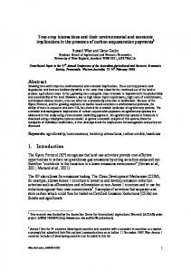
Propellant properties The determination of the coefficients of the change in velocity expressions requires the use of the propellant performance parameters (Isp and Isp,d). Despite the change in velocity expressions are valid for both types of propellants (monopropellants as well as bipropellants), separate sets of coefficients are determined for each type of propellant. For each type of propellant, numerous propellants have been considered for the calculation in order to enhance the accuracy of the determined set of coefficients. The considered propellants and their performance parameters are available in [1]. Coefficient values Calculation procedure The coefficient sets of Equation 11, Equation 14 and Equation 15 are calculated according to the procedure as outlined in Figure 1. As a first step, for every spacecraft, the mass ratio M’ is calculated for each propellant using Equation 8. The spacecraft initial mass Mi is assumed to be identical for all of the considered propellants. An average value M’av is deduced from these results and is used in the calculation of the exact value of the change in velocity v through Equation 9. In addition to the performance parameters Isp and Isp,d, the exact value of v is used in Equation 11, Equation 14 and Equation 15 to determine the coefficient sets Ci,prop for each propellant. As the
Ci,prop
Ci,av Figure 1 – The flowchart of the calculation of the coefficients for the simplified change in velocity equations 11, 14 and 15
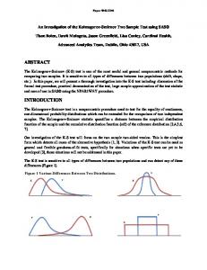
Dependence of the mass ratio M’ on the propellant density The derivative shown in Equation 13 and the use of an average value of M’ as described in Figure 1 are based on the main assumption that the coefficient M’ is both, independent of the propellant density as well as independent on the specific impulse density. However, the system mass depends partly on the propellant mass and the tank mass which are functions of the propellant density. The evolution of the coefficient M’ as a function of the propellant density has been determined for monopropellants and bipropellants combinations using several spacecraft characteristics and shown in Figure 2 and Figure 3 respectively. Based on these results, the coefficient M’ depends strongly on the spacecraft characteristics but it is for each of the considered spacecrafts almost constant over the considered propellant density range for both monopropellant and bipropellant combination. These results confirm the previously made assumption that the mass ratio M’ could be
Figure 2 – Evolution of the M’ ratio as a function of the monopropellant density for several spacecrafts
M' value
Evolution of M' value as a function of the bipropellant combination average density for several spacecrafts 0,8 0,7 0,6 0,5 0,4 0,3 0,2 0,1 0
e-Bird IntelSat VII SuperBird 6 900
1000
AMC 3 Hughes HS-601 Stellet 5 1100
1200
1300
Table 4 – Average values of the coefficients for monopropellants (based on IntelSat V characteristics)
The accuracy of the three different methods used in approximating the change in velocity value is investigated by determining the relative error of the approximated value by comparing it to the true value of the change in velocity for each of the three methods with the considered monopropellants. A representative result, obtained using IntelSat V characteristics is shown in Figure 4. This figure underlines the good accuracy of the defined approximating methods since the maximal relative error is less than 1.3 %. Comparison of the approximated change in velocity values Results based on IntelSat V characteristics
1400
bipropellant combination avergae density (kg/m3)
Results for monopropellants Only the results based on IntelSat V characteristics are discussed in this section. The coefficient set of each of the change in velocity approximation methods are gathered in Table 4 for the IntelSat V spacecraft. As can be seen in this table, the three methods lead to similar coefficient values.
ADN-based…
Hydrazine
1,40 1,20 1,00 0,80 0,60 0,40 0,20 0,00 HAN only (90%,wt)
As the M’ ratio value is roughly constant for all the considered monopropellant densities or bipropellant combination average densities and for all the considered spacecrafts, a propellant averaged value of the M’ ratio will be used in the following for each of the considered spacecrafts.
IErrorI (%)
deltaV*
Figure 3 – Evolution of the M’ ratio as a function of the average density of the bipropellant combination for several spacecrafts
deltaV**
deltaV***
Nitroglycerine
Propelant's density (kg/m3)
N-propyl nitrate
1700
1.71 0.11 3.19
Hydrogen…
1500
ACTS
Nitromethane
1300
AsiaSat
1.72 0.12
Hydrogen…
1100
IntelSat V
0.14
Methyl…
900
Jason-1
Linear relationship v***
1.72
Ethylammonium …
GlobalStar
Weighting method v**
Ammonium …
1 0,9 0,8 0,7 0,6 0,5 0,4 0,3 0,2 0,1 0
Tangent method v*
ADN-based…
M' value
Evolution of M' value as a function of the propellant's density for several spacecrafts
Approximation method of v 𝜕∆𝑣 𝜕𝑋1 𝑋 =1 1 /𝐼𝑠𝑝 ,𝑦𝑑𝑟𝑎𝑧𝑖𝑛𝑒 𝜕∆𝑣 𝜕𝑋2 𝑋 =1 2 /𝐼𝑠𝑝 ,𝑑,𝑦𝑑𝑟𝑎𝑧𝑖𝑛𝑒 a (m/s²) b (m/s²) c (m/s²) d (m/s²) e (m/s)
HNF (50%,wt)
considered both, independent of the propellant density as well as independent of the specific impulse density.
Figure 4 – Relative accuracy of the three investigated approximating methods for monopropellants
Results for bipropellant combination Only the results based on e-Bird characteristics are discussed in this section. The coefficient set of every change in velocity approximating method are shown in Table 5 for
the e-Bird spacecraft. As already observed for the monopropellant case, one notices that the three methods lead to similar coefficient values. Approximation method of v 𝜕∆𝑣 𝜕𝑋1 𝑋 =1 1 /𝐼𝑠𝑝 ,𝑁𝑇𝑂 /𝑀𝑀𝐻 𝜕∆𝑣 𝜕𝑋2 𝑋 =1 2 /𝐼𝑠𝑝 ,𝑑,𝑁𝑇𝑂 /𝑀𝑀𝐻 a (m/s²) b (m/s²) c (m/s²) d (m/s²) e (m/s)
Tangent method v*
Weighting method v**
Linear relationship v***
3.20
0.23 3.21 0.24 3.20 0.22 10.23
Table 5 - Average value of the coefficients for bipropellant combinations (based on e-Bird characteristics)
The accuracy of the three considered methods used for the approximation of the change in velocity value is investigated by determining the relative error of the approximated value by comparing it to the true value of the change in velocity for the three methods with the considered bipropellants. A representative result, obtained by using e-Bird characteristics is shown in Figure 5. This figure highlights the good accuracy of the defined approximating methods since almost all the relative errors are less than 0.05%. Comparison of the approximated change in velocity values results based on e-Bird characteristics
IErrorI (%)
deltaV*
deltaV**
deltaV***
0,45 0,40 0,35 0,30 0,25 0,20 0,15 0,10 0,05 0,00
Figure 5 – Relative accuracy of the three investigated approximating methods for bipropellant combinations
Discussion For all the defined linear approximations of the velocity change, the use of average value coefficient sets results in a good agreement between the approximated v*(*(*)) and the true value of v for all the investigated propellants. In addition to its simplicity and an ease of characterization, the weighting factor method (see Equation 14) seems to provide the most accurate approximation for almost all of the considered propellants and all the considered spacecrafts. Therefore, only this approximation method will be considered in more detail in the following sections.
Influence of the specific impulse and the specific impulse density on the change in velocity Observation The weighting factor method used in approximating the change in velocity is based on a linear relationship between the specific impulse and the specific impulse density with the weighting factors a and b, respectively. The value of each of these weighting factors defines the influence of each of the two propellant performance parameters on the value of the calculated change in velocity. The relative influence of both propellant performance parameters is analyzed for several spacecrafts. For each spacecraft, average values of a and b are considered. In Figure 6 and Figure 7, the weighting factors a and b are compared for several spacecrafts considering monopropellants and bipropellant combinations respectively. For both propellant types, a and b show different values depending on the considered spacecraft. Moreover, the weighting factor a is always about one order of magnitude larger than the weighting factor b over the whole range of considered spacecrafts.
Suggestion for an alternative performance parameter
Weighting factors considering monopropellants for several spacecrafts 3
Wighting factor value
2,5 2 1,5 a 1
The weighting factor method with average values of the coefficient sets results in accurate approximations of v for all the considered propellants and for all the considered spacecrafts. However, the value of v is strongly dependent on the spacecraft characteristics.
b
0,5 0
Figure 6 – Values of the weighting factors as specified in Equation 14 considering monopropellants for several spacecrafts
The influence of the spacecraft characteristics on the change in velocity results in a variation of the weighting factors a and b. One way to overcome this problem is to divide each of the weighting factors by their sum. From Equation 14, this consideration results in the following assessment criterion: 𝑓 𝐼𝑠𝑝 , 𝐼𝑠𝑝 ,𝑑 =
∆𝑣 𝑎 𝑏 = 𝐼𝑠𝑝 + 𝐼 𝑎+𝑏 𝑎+𝑏 𝑎 + 𝑏 𝑠𝑝 ,𝑑
Weighting factors considering bipropepellant combinations for various spacecrafts
Equation 16
As the sum of both of these new weighting factors is always equal to one, Equation 16 can be rewritten as:
8 Weighting factor value
7 6 5
𝑓 𝐼𝑠𝑝 , 𝐼𝑠𝑝,𝑑 = 𝐼𝑠𝑝,𝑢𝑛𝑖𝑓𝑖𝑒𝑑 = 𝛼𝐼𝑠𝑝 + 1 − 𝛼 𝐼𝑠𝑝,𝑑
4 3
a
Equation 17
2
b
Therefore, only a single coefficient is remaining in Equation 17.
1 0
Characterization
Figure 7 – Values of the weighting factors as specified in Equation 14 considering bipropellant combinations for several spacecrafts
Discussion Based on the results shown above, one notices that the weighting factor of the specific impulse is between 12 to about 15 times larger than the weighting factor relating to the density specific impulse. This result underlines that the influence of the specific impulse on the change in velocity v is significantly larger than the influence of the specific impulse density. Consequently, the specific impulse could be considered as the much more significant performance parameter in comparison to the specific impulse density for the comparison of several propellants.
Equation 17 provides a linear relationship between the specific impulse and the specific impulse density with a single coefficient expected to be independent of the technical characteristics of the spacecraft. The values of the parameter , related to all of the considered spacecrafts, are given in Figure 8 and Figure 9 for monopropellants and bipropellant combinations, respectively. As intended, the parameter shows only a very small scattering despite of the significant differences in the spacecraft characteristics illustrated by different propellants to initial mass ratios.
some key parameters such as the shell to tank mass correction factor K. The dependence of on K is investigated in the following section.
Alpha value as a function of the pacecraft characteristics for monpropellants 1 0,9 0,8 0,7 0,6 0,5 0,4 0,3 0,2 0,1 0
Dependence of on K Mp/Mi alpha
Figure 10 shows the evolution of as a function of K for monopropellants and bipropellants. The evolution of is almost identical for monopropellants and bipropellants. steadily decreases from about 0.95 to 0.80 when the value of K increases from 1 to 5. Dependance of alpha on K for monopropellants and bipropellants
Figure 8 – values as a function of the spacecraft characteristics for monopropellants
1,00 0,95
Alpha value as a function of the spacecrafts characteristics for bipropellants
alpha
1 0,9 0,8 0,7 0,6 0,5 0,4 0,3 0,2 0,1 0
0,90 0,85 0,80
Monopropellants
0,75
Bipropellants
0,70 0 Mp/Mi alpha
1
2
3
4
5
6
K Figure 10 – Dependence of on the shell to tank mass correction factor K for mono and bi-propellants
Figure 9 – values as a function of the spacecraft characteristics for bipropellant combinations
Figure 8 shows that ranges from 0.93 to 0.95 with an average value of 0.94 for monopropellants. For bipropellants, ranges from 0.91 to 0.93 with an average value of 0.92 as illustrated in Figure 9. By comparing the average values of for both types of propellant, it can be noticed that the values are close but not identical. Furthermore, one notes that f(Isp,Isp,d) defined in Equation 17 corresponds to the specific impulse in case a propellant with the density of water is considered. Therefore, the unified specific impulse defined in Equation 17 can be considered as a unified performance criterion to be used instead of the specific impulse or the specific impulse density. The obtained value of is valid over wide ranges of propellants and spacecrafts but it has been obtained by assuming constant values of
The decrease in for increasing K can be interpreted as a decrease of the specific impulse weight relative to the weight of the specific impulse density but the weight of Isp still remains much larger than the weight of Isp,d.
Summary The performance of a propellant is usually assessed either by the specific impulse or the specific impulse density. In order to prevent the use of two different performance parameters (which could lead to different rankings of a given set of propellants), an alternative way in ranking the propellant performance is the investigation of the change in velocity. Based on weighting factors, linear relationships between the change in velocity and both of the usual performance parameters have been successfully determined for wide ranges of both, propellants as well as spacecrafts. Despite the characterized set of coefficients for each spacecraft lead to a very good coincidence of the results for various propellants, the obtained weighting factors show
a strong dependence on spacecraft characteristics.
the
considered
Therefore, both of the coefficients of the defined change in velocity expression are divided by the sum of these coefficients. This results in the definition of an alternative propellant performance parameter which is slightly different for monopropellants and bipropellant combinations. This new performance parameter Isp,unified is linearly dependant on both of the usual performance parameters. The only remaining parameter of this expression is valid for a wide range of propellants and is independent of the considered spacecraft characteristics. An analysis of the evolution of this coefficient as a function of the shell to tank mass ratio factor K indicates that strong attention should be paid in the determination of K in order to ensure a high accuracy of the value of the parameter . However, in all the considered cases, the influence of the specific impulse on the suggested unified performance parameter remains always much higher than the influence of the specific impulse density.
Outlook Several assumptions have been made in this work leading to a certain extent to a restriction of the applicability domain of the final result. Several possibilities exist to make the final result more general as:
Having more detailed data about the spacecrafts in order to determine accurate values of the propellant masses. Considering tanks with different shapes, different materials and different burst pressures for the oxidizer and the fuel in the case of bipropellant spacecrafts. Considering the dependence of the M’ ratio (through an approximation at least) on the propellant specific impulse density.
Acknowledgement The research leading to these results has received funding from the European Community´s Seventh Framework Programme
(FP7/2007-2013) under grant agreement n° 218819. Also, the authors would like to thank Mr. Robert Jan Koopmans from SOTON for his help in defining the basic equations on which this work is based on.
References [1] G. Robert et al., Green Advanced Space Propellants – General Assessment of Green Propellants, GRASP Doc. No. D2.1, [2] C. Scharlemann, Green Propellants: Global Assessment of Suitability and Applicability, 3rd European Conference for Aerospace Sciences, (EUCASS), Versailles, France, 6-9 July 2009 [3] C. Scharlemann, GRASP-A European Effort to Investigate Green Propellants for Space Application, 2nd Space Propulsion Conference, San Sebastian, Spain, 3-6 May, 2010 [4] R. A. Nelson, Rocket Thrust Equation and Launch Vehicles, http://www.aticourses.com/rocket_tutorial.htm (Assessed on the 28th April 2010) [5] http://space.skyrocket.de/ (assessed on the 28th April 2010) [6] http://www.astronautix.com/craft/jason.htm (assessed on the 28th April 2010) [7] http://www.astronautix.com/sites/kouuela3.htm (Assessed on the 28th April 2010) [8] http://www.boeing.com/defensespace/space/bss/programs.html (assessed on the 28th April 2010)