SPEEDAM 2008 International Symposium on Power Electronics, Electrical Drives, Automation and Motion
AC Motor PWM Control System Based on x86 Processor Board and Linux-Embedded OS C. Bruzzese, E. Santini, and D. Sciunnache Department of Electric Engineering, University of Rome, Sapienza Via Eudossiana 18, 00184, Rome, (Italy) e-mail:
[email protected] Abstract – The continuous enhancement of microprocessor (μP) performances, operating systems (OSs) and communication networks are pushed forward by the rising request of graphical, multimedia and control applications and of high-speed industrial and general-purpose communication tools. OSs have been embedded in a evergrowing number of applications, and their use has been recently extended to industrial drives. In this work an experimental PWM motor drive has been realized by using a common x86-based platform supported by a Linuxcompatible operating system. Thanks to a multi-tasking embedded OS, the drive’s CPU can simultaneously perform parallel processes such as drive control, drive and machine diagnostics, and high-speed communication toward field and upper plant levels, each process being assigned with a different priority level. The drive is mainly dedicated to future research about these enhanced functionalities. Hardware, devices, and Linux-OS resources used for drive realization have been described, with experimental results.
II. TRENDS OF COMPUTATIONAL AND NETWORKING RESOURCES IN THE INDUSTRY
Industrial processes are more extensively integrated because this offers the opportunity of improving production efficiency and of implementing powerful tools for plant monitoring. A key task is carried out by the communication equipment connecting the control systems with shop-floor devices such as electric drives, actuators and sensors. The increasing volume of exchanged data pushed for many novelties in the communication equipment, initially based on point-topoint lines transmitting analogue quantities, which has moved toward serial buses transmitting digital signals, i.e. the fielbuses. Architectural solutions chosen for process integration and communication protocols utilized for data exchange have become central issues [2]. Actually, under the standard IEC61158/ISA SP50.02 a number of different protocols coexist, i.e. ControlNet, Profibus, P-Net, Fieldbus Foundation HSE, Swiftnet, WorldFIP and Interbus, beside non-standard protocols. The IEC is working to integrate the shop-floor devices, and for integrating the electric power drives (IEC 618007). Architectures able to support the process control right down to the field level and real-time deterministic control of single and multiple drives [3] are of concern. Trends of architectures. Drive integration architectures for motion control are evolving from classical centralized PLC-based architectures to PC-based and finally toward intelligent drive-based delocalized architectures [2], with consequent greater plant hardware integration and cabling simplification. The evolution from the PLC-based to the PC-based architectures, still centralizing control functions such as trajectory generation and axis regulation, allows a broader integration of HMIs (Human-Man Interfaces) for driver setting. The intelligent drives interact among them and with the upper control levels. They support floating point operations, multitasking and enhanced debug properties. The technological functions are available to the user as proprietary not-open modules and operative templates (positioning, speed or torque loop, etc.). Trends of fieldbuses and protocols. Fieldbuses can be grouped in supervisory buses (for non cyclic nor timecritical data flow between management and cell plant layers), device buses (for cyclic, non time-critical data exchange between cells and shop-floor devices), and drive buses (for cyclic, time-critical formatted data transmission and drive control on the field layer). When
I. INTRODUCTION Control systems empowered by embedded OSs (EOSs) are growing in importance, and they are going to replace early systems endowed by dedicated proprietary software. The advantages offered by an EOS are: high-level programming, easy task scheduling, simpler hardware resources accessing by using general-purpose device drivers. Multi-core μPs are nowadays available, and multi-tasking EOSs can better manage parallel tasks. General purpose μPs, besides advantages offered by the greater computation power and programming easiness, realize substantial cost reductions due to hardware cheapness and software development rapidity. In this work, an experimental PWM motor drive has been realized by using a common x86-based platform supported by a Linux-compatible OS [1]. An apposite interface-board has been built up, which collects signals from the main-board through the parallel port, and drives an intelligent power module (IPM) through optocouplers. While controlling the motor, the mainboard provide many other useful functions, such as plant communication and drive diagnostics. Test and experimentation on these advanced capabilities are the main purposes of our inprogress research, considering that tomorrow’s intelligent drives will be requested to accomplish more complex and sophisticated full-integrated features. So, the prototype has been mainly realized for functional tests on the EOS and software. After a review of trends in industrial automation, this paper describes hardware components and Linux-OS resources used for drive realization. 978-1-4244-1664-6/08/$25.00 ©2008 IEEE
1069
the number of devices does grow and/or their dynamics become faster, the buses need for real-time features, and for protocols assuring determinism, synchronism and repeatability, [4]. Typical fieldbuses are: SERCOS (Serial Real Time Communication System), Profibus DP and PROFIdrive, and the time-triggered networks with deterministic protocols, such as TTP (Time Triggered Protocol) [5], FlexRay [6], and TTCAN (Time Triggered CAN) [7], which use TDMA (Time Division Multiple Access). An approach of increasing interest is the extension of structures and protocols underlying Internet (i.e. Ethernet and the Transfer Control Protocol, TCP/IP) to the industrial automation. Due to their diffusion and openness, the manufacturers would really compete in developing solutions for greater integration between executive and office activities. Ethernet, initially used for LAN networks, has been extended to the World Wide Web thanks to the TCP/IP interface. Recently, Ethernet networks for the industry have been developed [8]. Their usage in the cell and field levels is appealing for many reasons: consistency with the communication systems installed at higher levels, short cycle-times due to the high transmission speed, large availability of chips implementing the Ethernet protocol and use of IT utilities for services and diagnostics. In some appliances, Ethernet is expected to take over the functions of today’s fielbuses. At the moment, a pure real time Ethernet network has not been developed, even if some manufacturers have incorporated Ethernet in their fieldbuses, such as PROFInet, Ethernet-IP, Fielbus Foundation HSE (High Speed Ethernet), and Ethernet Powerlink [2]. Significant enhancements are the increase of transmission speed (from the initial 10Mbit/s to 100Mbit/s (Fast Ethernet), till to 1Gbit/s and 10Gbit/s) and the introduction of the Switched Ethernet. The switch recognizes the addresses of the station connected to it and redirects the messages to the destination only, instead of to all the stations, so reducing collision eventualities. For full real-time operation, a viable solution is the User Datagram Protocol (UDP). UDP is placed above IP but, differently from TCP, it is a connectionless protocol which tests the transmission correctness by using a simpler technique based on the bit checksum, and does not execute any data flow control. The UDP transmission overhead is small and the data transfer efficiency is higher, but less reliable. An enhancement is the Power-on-Ethernet (PoE) network, where the nodes are energized by means of the same twisted-pair cable used for the data exchange. Power-source nodes recognize and feed non-powered nodes, without use of external feeders. Trends of computational resources. Network and drive evolution is heavily influenced by the available hardware’s computational resources. The progress, however, not always is straightforward and univocal. CPU cores belonging to CISC, RISC and DSP architectures differentiated much in the past owing to their different applications [9]. A brief review follows. CISCs (Complex Instruction Set Computers, e.g. x86, 68000) systems manage an extended machine instruction set, and any instruction is suited for complex operational
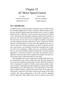
tasks, over many clock cycles. High-level machine programming is allowed, along with more powerful peripheral control. General-purpose computers and common desktop PC belong to this category. RISCs (Reduced Instruction Set Computers: AMD 29000, POWER PC, ARM) have simpler and quick onecycle instructions. Programming is slower and more laborious than with CISCs, but simpler hardware and greater affordability made RISCs widespread in professional applications (Work-Stations, μcontrollers). DSPs (Digital Signal Processors) are structurally optimized for an extremely effective management of instruction loops in real-time digital signal conditioning and elaboration tasks. The hardware is sturdy, with onchip embedded RISC elaboration unit and D/A and/or A/D conversion peripherals, and the costs are kept low. The computation power evolved in different ways for these categories, accordingly to market requirements and user needing. DSPs and RISCs dominate until ’90s, but with the new century CISCs have prevailed (the formers doubled their power about every five years, whereas CISC every single year, pushed on by increasing demands from multimedia). Actually, common PC performances amount to as much as 20÷50 times those of state-of-the art industrial DSPs. Nowadays a progressive convergence has been noticed since CISC instruction sets have been kept bounded, whereas RISC instructions are growing in number and complexity, due to cost reduction of circuit fabrication processes. DSP core power will continue to increase in the future, and multi-core architectures easily will find new applicative spaces in industrial applications, for a number of reasons: - more sophisticate and precise control features are required by the industry; - different modern control strategies (fuzzy, neural, etc.) demand for large computational resources; - high-level control algorithms can be managed easier and faster, with less restriction of CPU-cycles, and greater code portability; - other functionalities can be added, such as automatic decentralized monitoring to a low plant-level; - enhanced connection (TCP/IP) with lower and upper plant layers. - operative system embedding, and multi-tasking features for more “intelligent” drives. III. CONTROL SYSTEM HARDWARE AND STRUCTURE The power VSI drive realized for experimentation about enhanced-feature drives is made up by a rectifier part (three-phase diode bridge and capacitor set on DClink) between the power utility and the inverter (two-level three phase IGBT bridge and brake transistor), Fig.1. The acquisition and conditioning board converts motor currents in voltage signals, and forward them to the main board. The CPU (AMD64) cyclically performs output voltage computation on external IRQ, with pre-selected loop rate (up to 20kHz), and pushes the three calculated duty ratios to the control board. Digital input signals are used to produce PWM control signals for higher and lower transistors; the final link with the IPM (Intelligent
1070
LINE
ELECTROLITIC CAPACITOR
RECTIFIER
BRAKE CONTROL
TABLE I. EPP DB25 CONNECTOR PINS AND SIGNALS.
IGBT INTELLIGENT POWER MODULE
Pin 1 2÷9 10 11 12÷13 14 15 16 17 18÷25
OPTOCOUPLERS
12-24 V I/O MONITOR
KEYBOARD
IPM DRIVER
PARALLEL PORT (EPP) X86 MAIN BOARD OS LINUX AUDIO CARD
HALL PROBES
SIGNAL ADAPTER
ELECTRIC MOTOR
ETHERNET
EPP name /Write Address/Data 0÷7 IRQ /Wait Custom /Data Strobe Custom /Init /Address Strobe GND
EPP function Write command Data/Address Bus Interrupt request Synchronization Programmable Data ready Programmable Peripheral reset Address ready Ground
Direction Out In/Out In In In Out In Out Out -
socket 939 for AMD64 processors, and based on chipset VIAK8T800Pro and VIAVT8237), equipped with a 2Ghz system bus and two parallel dual-channel 512MB RAM memory banks. The main board controls the power devices through two interfaces – the driver and the data acquisition interface, Fig.1. The main-board μP performs a real-time update of 8254 Counter-Timers (CTs), writing the duty ratios to CT registers via parallel port (PP), so obtaining an instantaneous output voltage PWM control. Software-generated timing signal frequency is the same as PWM switching frequency. The latter is selected depending on the modulation algorithm, and on the power module (IPM), and its thermal limits. The onboard Ethernet interface has been dedicated to data exchange with a remote client, see Section VI. b) Parallel Port: Parallel port operating modes have been defined by the IEEE 1284 standard, as: SPP (Standard Parallel Port), EPP (Enhanced Parallel Port), and ECP (Extended Capabilities Port). The μP communicates with the driver interface thorough the EPP, which embeds the following features: - SPP – compatibility; transfer speed up to 2MB/s; - bidirectional communication by eight dedicate registers; - automatic data transmission and signal handshake. EPP data/address handshake signals are listed in Table I.
Fig.1. Scheme of the realized drive.
IC3
IC2
IC1
U2
U1
Power Module) is realized via an optocoupler interface. This hardware solution permit to separate the elaboration task from the PWM signal generation, whereas common dedicated DSP-boards must face both tasks. The control algorithm can be more quickly and easily implemented by using high-level languages and without heavy restrictions on timing and memory space, so facilitating the research work about innovative drive features. The multi-tasking feature is mainly of concern, and it will be exploited in future works by implementing additional software tools for various research purposes. The large computation resources available will be exploited for investigation about on-line diagnostic algorithms and procedures. MCSA, for example, needs signal conditioning and elaboration (FFT, wavelet analysis, etc.) that can be performed inside the same drive. Drive networking by exploiting TCP/IP protocols is the other major concern. The facilities embedded in the drive are being currently used for educational and teaching purposes, too. A short description of the main drive components and operation follows: a) Main Board: The control system is based on a standard-format ATX x86 main-board (ASUS A8V with
Fig.2. IPM driver board circuit.
1071
c) Driver Interface: The IPM driver interface performs the following tasks: 1) PWM signal generation, 2) fault management, 3) brake resistor control, and 4) eight general-purpose on/off load driving. Fig.2 shows the electrical layout realized. The five logical circuits (U1,2, IC1,2,3) which accomplish functions 1) - 4) are completely addressable and controllable from the mainboard CPU. IC1 (74HCT374N) addresses the circuits by storing an 8-bit address from EPP A/D lines when the ASTROBE signal goes high. Basically, two CMOS programmable interval timers/counters 8254 (U1,2) are connected to the system buses for PWM signal production as in Fig.3. The TTL-logic IC 8254 contains three 16-bit counters connected by an 8-bit internal bus (Fig.4), with six different programmable operating modalities, and clock frequency up to 12MHz, [10]. The three-state, bi-directional, 8-bit buffer is used to interface the 8254 to the system bus. The Read/Write Logic accepts inputs from the system bus and generates control signals for the other functional blocks. A1, A0 select one of the counters or the Control Word Register (CWR) to be read from/written into. /RD and /WR inputs tell the 8254 that the CPU is reading a counter or writing either a Control Word or an initial count. These inputs are ignored unless the 8254 has been selected by holding /CS low. The CWR manages the real-time counter update. Counter#0 of U1 in Fig.3 is used as programmable frequency divider, so producing trigger signals with frequency fclock/Ns (fclock=6MHz, Ns=300 in experimental tests). U1 sends the trigger pulses to U2 and to CPU (IRQ synchronization signals). Moreover, U1 controls the brake circuit by using Counter#2 and performs fault typology recognition and fault duration measure by Counter#1. The trigger pulses reset the counters of U2 and new values coming from CPU are stored for countdown at every switching period. Counter outputs (A, B, C in Fig.3) go down when the counting expire, and so edgealigned PWM signals (Fig.5) come to the Schmidt triggers for blanking time generation and then to optocouplers for IPM driving. Counter#2 of U1 operates in a similar manner, for PWM control of brake IGBT. To obtain a PWM pulse with duty ratio D, the starting value to write in the counter is (1), where Ns is fclock/fswitch. Ni =
Ton ,i ⋅ Ns = D ⋅ Ns Ts
Fig.4. IC 8254 internal logic architecture.
The CPU computes the new Ni values between two IRQs, according to the high-level language control algorithm stored in the RAM, and then writes them into U2’s counter registers, which execute the new countdown when the second IRQ is triggered. The braking transistor is both software and hardware controlled, to avoid DC-link over-voltages and damage to the electrolytic capacitors. Hardware control is automatically provided, by a feed-back action from DClink voltage measure, and warning threshold voltage (600V) crossing detection. Software control is provided by the CPU driving Counter#2 of U1, to maintain a steady regulated voltage level on the capacitor bank. Inverter fault occurrences are managed at both hardware (by the interface) and software (by CPU) level. The IPM provides automatic IGBT protection against malfunctioning such as short-circuit, driver undervoltage, and overwarming (see point e). When a fault happens, the IPM set a current fault signal (10mA) from the fault pin of the single high-side IGBT, or from the fault pin shared among the low-side IGBTs. The signal duration is used to discriminate the fault type. The signal drives the U1’s counter#1 gate, which measures the fault time duration. After the fault signal has been received, the CPU waits for few milliseconds, and then reads counter#1’s register. Based on the duration, a short-circuit can be distinguished from over-warming and under-voltage faults. Moreover, the driver board memorizes into IC2’s latches (74HCT541N) the four fault pin status, which is reported to the A/D bus of the EPP, so allowing the CPU to recognize the fault source. Other predefined fault sources are: manual stopping, drive case opening, and EPP socket disconnection. Every kind of fault produces counter-
(1)
CPU AMD64
clock DATA BUS
gate
ADDRESS BUS CONTROL BUS
out 0
IRQ
A Ton
FAULT
U1 8254
TRIGGER
U2 8254
Toff
A
out 1
B
B
C
out 2 clock
C Ts
BRAKE
Fig.5. Edge-aligned PWM signal timing.
Fig.3. PWM signal generation unit on the driver board.
1072
e) IPM, rectifier and capacitors: An integrated 75A, 1200V IPM (Intelligent Power Module) Mitsubishi Lseries PM75RLB120 has been used, with seven power IGBTs, free-wheeling diodes, driver circuits and built-in short-circuit, thermal, and control supply under-voltage lock-out protections, [12]. The internal control circuits operate from four isolated 15V DC supplies. If a supply voltage drops below the trip level (12V), the IGBTs are turned off and a fault signal is generated from the IGBT driver, as long as the fault persists. A temperature sensor on the base plate near the IGBT chips senses the overtemperature trip level (145oC) overcoming, so allowing to turn off the IPM. A low-side fault signal lasts for the over-temperature condition time duration. The currentsense IGBT monitors the actual current. If a load shortcircuit occurs or the system controller malfunctions causing a shoot-through (short circuit trip level is 150A on the inverter part and 80A on the brake part), a controlled shutdown is initiated and a fault output is generated for a time duration of 2ms. The three-phase diode bridge rectifier IXYS VUO 160-08N07 (175A, 800V) is coupled to four seriesparallel connected 450V, 2200μF electrolytic capacitors. Fig.11 shows the Simulink power drive model, used for component rating planning and system performance evaluation. As example of the work carried out in this stage, the dimensioning of the capacitor bank will be here described. Since the capacitors are by far the most vulnerable drive components, special attention has been paid to their specifications. So, harmonic analysis of the capacitor charging current and estimation of the consequent thermal dissipation on the internal ESR (equivalent series resistance) have been included in the model. ESR depends on both frequency and temperature [13]; so, the heating power developed inside the capacitor can be estimated by adding the contribute of each current harmonic through the correspondent ESR, in the worst case of maximum allowed hot-spot temperature, (3).
Fig.6. Driver interface board.
-trigger and IRQ inhibition, PWM turn-off and load disconnection. Finally, the driver interface IC3 (74HCT154N) allows the CPU to command eight independent general-purposes on/off loads, four 12V loads (relays, fans, etc.) and four 24V loads (e.g., contactors), with current limit of 2A. The realized board appears as in Fig.6. d) Current Acquisition Board: The analog current signals furnished by four Hall-effect probes (three phase currents and the brake-shunt current) must be conditioned before they enter the acquisition cards [11]. Two audiocards (chipset CT1297 standard AC97) with two ADC channels each have been used, with sampling frequency up to 48kHz and 16-bit resolution. Depending on the sampling frequency, the chipset AC97 selects the proper on-board anti-aliasing filters. The optimal pass-band is 5Hz÷20kHz, without attenuation. The range has been extended to DC, bypassing the on-board input series capacitor, and applying to the input signal the needed offset voltage (1.37V). The signal adapter interface (Fig.8) performs this task, along with current-voltage signal conversion in the useful audio-card input range (±1.5V), according to (2), by using Op-Amps as in Fig.7. U3 = U 2 ⋅
R4 R3 + R4
⎛ R ⎞ R ⋅ ⎜⎜1 + 2 ⎟⎟ − U1 ⋅ 2 R1 ⎝ R1 ⎠
(2)
n
P = ∑ ESR ( f i , Tmax ) ⋅ I ( f i ) 2rms
(3)
i =1
The steady-state hot-spot temperature is then furnished by (4), where Rth,ha is the hot spot-ambient thermal resistance obtained from manufacturer’s data sheets. (4)
Ths = Ta + ( P ⋅ Rth ,ha ) Fig.7. Inverting Op-Amp (IC TL074) for signal adaptation.
Computations have been carried out by considering Tmax=85oC, and Ta=50oC (rack internal temperature). Since the capacitor current had important frequency components multiple of 300Hz (from the rectifier) and around the multiples of IPM’s switching frequency (20kHz), the pass-band filters in Fig.11 were adequately tuned [14]. The used ESR values are listed in Table II. TABLE II. ESR VALUES AS FUNCTION OF THE FREQUENCY (85OC). f [Hz] 300 600 900 1200
Fig.8. Signal conditioning board with Hall-effect probes.
1073
ESR [mΩ] 17.11 14.21 13.34 12.70
f [Hz] 1500 1800 20000 40000
ESR [mΩ] 12.35 12.18 11.8 11.6
500 A 400
1200 o C 1000
300 200
800
100 600
0
85 °C
-100
400
-200 200
-300 -400
0
0.05
0.1
0.15
0.2
0.25
0.3
s
0
0.35
0
0.05
0.1
0.15
0.2
0.25
0.3
s
0.35
Fig.9. Simulated motor currents (sinusoidal PWM).
Fig.10. Capacitor hot-spot temperature.
In Fig.9, a starting transient with full-load steady-state is shown (without insertion of the current-limiting starting resistor on DC-link, to shorten the simulation).
Fig.10 shows the capacitor hot-spot temperature computed by (4) (only the steady-state is meaningful).
Fig.11. Simulink drive model used for power component rating and planning.
IV. EXPERIMENTAL TESTS The drive control board operation has been tested experimentally; the first tests concerned the correct
communication through the parallel port, carried out by checking that handshake signals were conform to the EPP standard. Figs.12-15 show the obtained results.
Fig.12. Handshake for address writing: ideal (left) and measured (right).
Fig.14. Handshake for data writing: ideal (left) and measured (right).
Fig.13. Handshake for address reading: ideal (left) and measured (right).
Fig.15. Handshake for data reading: ideal (left) and measured (right).
1074
Fig.16 shows the PWM inverter output voltage signals and their synchronization with the internal board trigger/IRQ signal; in Fig.17 the signals controlling the upper and lower transistors in the same inverter leg appear, for two different duty ratio values (8254’s counter has been loaded with N=20 and then with N=30. Dead time=3μs).
set of primitives (system calls) to implement OS’s services such as process and multitasking management and system hardware resource (e.g. the memory) sharing among the various processes, in modules running under supervisor modality [1]. Inside the kernel’s modular structure, the scheduler controls the task execution by assigning CPU time slots to the parallel processes and threads, on the ground of rules stated by a SP (scheduling policy). Besides the basic functions, other OS’s modules provide services for protocol-based communications and the user interfaces. The tight kernel’s module internal integration makes the kernel itself very efficient. Linux kernel can upload and set up new modules while running. Scheduling modalities: Linux-based OSs are easily adaptable for industrial uses, since they can realize various types of SP, including hard and soft real time schedulers, by exploiting the preemptive feature. To every process corresponds a given priority and a SP assignation. Standard Linux kernel uses three different SPs, two (FIFO and RR) with static and one (OTHER) with dynamic priorities [1]. The FIFO (First-In First-Out) SP imposes a higher priority process to be entirely executed before other with lower priority. The Round Robin (RR) SP is similar to FIFO, but the process is allowed to run for a given time period, after which the CPU is released. OTHER is the standard SP commonly used with all processes. A maximum running time is assigned to a process, into a broader time division (epoch). The process priority is the sum of a fixed term and a term lessening as the process consumes its CPU time. Kernel’s modules are not subjected to scheduling (as the processes in the user space), so no latency due to change of context slow down their execution. IRQ management: The IRQ management is only possible in the kernel space, so an external device needs to interface with a kernel’s module to exploit IRQs. This can be done in two ways: a) a kernel’s module can be created which senses the IRQ, performs calculations and updates the interface’s registers through the parallel port; b) a kernel’s module is programmed which only receives the IRQ and sends data output through a virtual peripheral (device). A process in the user space executes a locking reading on the virtual peripheral, which is released when data are available, so starting the computation cycle and interface register update. The first solution is the best for hard real time applications, since the kernel module is not subjected to scheduling, so guaranteeing time limit respect in any CPU working condition. In the second solution the userspace process must be assigned with a high static priority; however, the process itself can be programmed by using standard functions [15, 16]. The PWM signal generation process controlling the IPM driver board has been implemented as in the user space, with FIFO SP and highest priority. So, the context change toward the process, following an IRQ, is immediate, and the process completion is granted. The secondary processes (such as current acquisition and analysis, and system remote management services) can be set with lower priorities, or
Fig.16. PWM edge-aligned signals and trigger/IRQ pulses.
Fig.17. PWM branch control signals for upper and lower IGBTs.
V. LINUX OS AND PROCESS SCHEDULING The Linux OS is well-suited for control system applications, thanks to features such as: 1) easy hardware access, 2) flexibility in hard-real time control applications, and 3) great operating stability. These features justify the widespread diffusion of Unix OSs into the network servers and in OS-embedded controllers. The main features of the OS used in the control system are: Linux OS: The software written to control the drive circuits is based on Linux OS v.2.6.15. The distribution Fedora Core 5 has been installed on the selected hardware platform, with all the drivers, libraries, peripheral control functions, and development tools. In this way the same platform has been used as both Host and Target board. The realized system is made up by: a) the kernel, containing the basic OS functionalities, started from BIOS by a bootloader program (LILO, GRUB) at computer turn-on; b) some essential modules, which make available the kernel’s services (e.g. the TCP/IP stack, SSH, etc.); c) the applicative programs, not belonging to the OS (e.g. the PWM control program). Kernel: The Linux’s monolithic kernel constitutes an high-level interface to the hardware, since it furnishes a
1075
with the predefined SP, and they are tidily executed in the time remaining between two main program’s iterations.
with a remote computer (host). A FTP client is installed on the host. The FTP server permits to the host to manage the server’s filesystem (file upload and download). All the registered information in normal/faulty operation can be collected and used for better system knowledge and process optimization, as well as for diagnostic purposes.
VI. COMMUNICATION PROTOCOLS AND SERVICES The Ethernet interface used in the drive allows the system to communicate with hosts to transmit/receive commands, files, and system status information. Linux OS integrates the protocols TCP/IP, UDP and various services (servers) which permit different remote interaction modalities, such as SSH, FTP, HTTP. Besides these, other services can be realized by exploiting the OS’s protocols, as the measure streaming thorough UDP. The various protocols and services are here described. TCP/IP stack: Linux OS’s kernel embeds a TCP/IP stack, made up by the following layers: - Application: network interface program, based on the client-server model, with application-specific protocol. - Transport: this layer regulates connection and data exchange between two terminal stations with dialoguing applications. TCP and UDP are connection-based protocols with the services for checking the transmission errors and controlling the data flow [17]. According to the used protocol, the transport can be affordable and slower (TCP), or non-affordable and faster (UDP). In industrial environments, TCP is best suited for communication between the higher plant levels (cells, areas, [2]), whereas UDP can accomplish fast and short datagram exchange among drives on the plant shop floor. - Network: on this level data packets are switched and sorted on a complex interconnected network. The protocol used here (IP) provides segmentation, routing and reassembling of the message into data packets, as well as packet clearing, control message exchange, and network monitoring. - Interface: IP is interfaced to the physical medium via a network adapter, which implements the Ethernet protocol. It manages the packet I/O from/to the medium. Server SSH: A server is an applicative program which makes available a service through a network. By exploiting a communication protocol, like TCP/IP, a program (client) running on a remote machine, contacts the server for service request and data exchange. Linux OS allows the installation of all most common server types. The server SSH (Secure SHell) permits to establish a coded remote connection into a command line interface. The remote user, after a password and an ID has been entered, can control the computer (host) on which the server is running, by using the available shell commands. Server HTTP: The HTTP (Hyper Text Transfer Protocol) permits to load pages on a remote computer HTML (Hyper-Text Mark-up Language) by using an Internet browser. By installing a HTTP server on the drive control system, the drive itself can be remotely controlled by using HTML pages on a host. A system status synoptic window can be inspected, operating parameters can be set, and commands passed to the running processes. Executable ‘script’ programs can be added to the HTML page, for drive control. Server FTP: The FTP (File Transfer Protocol) server is an FTP-based applicative which allows file exchange
VII. CONCLUSION An experimental PWM drive based on nonconventional hardware and software (x86 board, Linux OS and the appositely constructed interface board and control program) has been described, for research about intelligent drives using TCP-UDP/IP protocols and nonproprietary software. The multitasking feature for control, monitoring, and networking is the main research focus. REFERENCES [1] Rubini A.; Corbet J.; Kroah-Hartman G.: Linux Device Drivers, O’Reilly, 2005. [2] E. Bassi, F. Benzi, F. Calegari, M. Bertoluzzo, G. Buja, “Integration Architectures and Communication Protocols for Electric Drives,” in Proc. of SPEEDAM 2004 conf., 1618 June 2004, Capri, Italy, pp.143-152. [3] M. Felser, “Comparison of Different Interfaces and Profiles for Power Drive Systems,” in Proc. of SPEEDAM 2004, 16-18 June 2004, Capri, Italy, pp.153-158. [4] G. C. Buttazzo, Hard Real-Time Computing Systems, Kluwer Academic Publisher, Boston, 1997. [5] TTTech: Time Triggered Protocol TTP/C, High level Specification Document, 2002. [6] C. Temple, Protocol Overview, FlexRay International Seminar, Tokyo, June 2003, available: www.flexray.com/publications.php. [7] CiA TTCAN-Time Triggered CAN, available: www.cancia.de/can/ttcan. [8] M. Bertoluzzo, G. Buja, and S. Vitturi, Ethernet Networks for Factory Automation, IEEE Industrial Electronics Society Newsletter, pp.5-10, Dec.2003. [9] Falaschi A.: Elementi di Trasmissione dei Segnali e Sistemi di Telecomunicazione, Aracne Ed., 2005. [10] 82C54, Harris semiconductor, 1997. [11] Sound card based multimeters, www.qsl.net/om3cph/sb/dcwithsb.htm. [12] Using intelligent power modules, Mitsubishi Electric, 1998. [13] Electrolytic Capacitors Application Guide, Revox Rifa, www.evox-rifa.com. [14] Mohan N.; Undeland T.; Robbins W.: Power electronics, Wiley & Sons, 1995. [15] Saikkonen R.: Linux I/O Programming mini how-to,
[email protected]. [16] Piccardi S. (2006), GaPiL Guida alla Programmazione in Linux, gapil.firenze.linux.it/. [17] Information Sciences Institute, University of Southern California: RFC 793 Transmission Control Protocol specification, Sept.1981 available: www.ietf.org/rfc/rfc0793.txt.
1076