TECHNICAL NOTE: ALGORITHMS FOR PARAMETERIZATION OF DYNAMICS OF INERTIA‐BASED APPLE ORIENTATION A. M. Lefcourt, P. Narayanan, U. Tasch, R. Rostamian, M. S. Kim, Y. R. Chen ABSTRACT. Development of machine vision systems to inspect apples for defect and contamination problems has been stalled due to lack of a commercially‐viable method for appropriately orienting fruit for imaging. We recently discovered that apples could be oriented based‐on their inertial properties by rolling the apples down a track consisting of two parallel rails. As angular velocity increased, apples moved to an orientation where the stem/calyx axis was perpendicular to the direction of travel and parallel to the plane of the track. Empirical tests suggested that track flexibility plays an important role in this orientation process. However, the orientation process occurs very fast and visual observation is inadequate for detailed analysis of this process. The objective of this study was to assemble hardware and software that could be used to acquire movies of the orientation process and to automatically analyze the movies. Specific goals were to quantify the location and degree of orientation of the apple, and the position of the track, in each movie frame. Movies were successfully acquired in AVI‐format. Results of tests using 14000 frames demonstrated that the specified goals could be met with essentially no error. However, use of the system in experimental trials revealed some problems and highlighted the importance of correct lighting. In particular, the software was modified to address errors associated with an apple still being on the track in the last frame of the movie and to allow the video acquisition system to be tuned and calibrated prior to experimental trials. Keywords. Apples, Imaging, Machine vision, Algorithms, Stem, Calyx, Food safety.
M
achine vision is increasingly used for automated inspection of agricultural commodities (Brosnan and Sun, 2004; Chen et al., 2002). Researchers have developed computer‐imaging methods for detecting bruised and diseased fruit (Brown et al., 1988; Li et al., 2002; Kleynen et al., 2005; Mehl et al., 2004; Throop et al., 2005) and feces‐contaminated fruit (Kim et al., 2002; Lefcourt et al., 2003, 2005). However, application of these methods in a commercial environment has been hindered by the difficulty of discriminating the stem and calyx regions from problem sites. This dilemma could be resolved if apples were appropriately oriented prior to image acquisition. We recently discovered that apples could be oriented based‐on their inertial properties (Narayanan et al., 2006, 2007). Unfortunately, this orientation process happens so fast that visual observation is inadequate to determine how, or
Submitted for review in January 2007 as manuscript number IET 6818; approved for publication by the Information & Electrical Technologies Division of ASABE in November 2007. The authors are Alan Marc Lefcourt, ASABE Member Engineer, Research Biomedical Engineer, USDA‐ARS, Henry A. Wallace Beltsville Agricultural Research Center, Beltsville, Maryland; Priya Narayanan, ASABE Member Engineer, Graduate Student, Uri Tasch, Professor, Department of Mechanical Engineering, Rouben Rostamian, Professor, Department of Mathematics and Statistics UMBC, Baltimore, Maryland; Moon S. Kim, Research Biophysicist, and Yud‐Ren Chen, ASABE Member Engineer, Supervisory Agricultural Engineer, USDA‐ARS, Henry A. Wallace Beltsville Agricultural Research Center, Beltsville, Maryland. Corresponding author: Alan M. Lefcourt, USDA‐BARC‐ANRI‐FSL, Bldg. 303, Powder Mill Rd. ‐ BARC East, Beltsville, MD 20705; phone: 301‐504‐8450; fax: 301‐504‐9466; e‐mail:
[email protected].
sometimes even if, apples become oriented. The objective of this study was to develop an automated system that could be used to acquire movies of the orientation process and software to analyze the movies on a frame‐by‐frame basis. Currently, sorting of apples for surface defects is mainly done by manual inspection (Bennedsen and Peterson, 2005) and no commercial system is available for detecting fecal contamination. The principle impediment for adoption of machine vision systems for these purposes is error generated by the visual complexity of the stem and calyx regions. Complex image processing algorithms that detect the stem and calyx regions have been written to address this problem; however, these methods are usually expensive and time‐consuming (Bennedsen and Peterson, 2004; Kleynen et al., 2005; Penman, 2001; Throop et al., 2005). Alternatively, a secondary imaging system can be used to identify the stem and calyx regions, again a costly option (Wen and Tao, 2000). For defect detection, the ability to orient apples prior to imaging would allow the development of imaging systems that exclude these regions from acquired images or that include detection algorithms optimized to use knowledge of the locations of these regions in images. For contamination detection, it is important to fully image the stem and calyx regions. As these regions are concave in structure, it would be necessary to use multiple imaging perspectives to guarantee the ability to image 100% of the surface of randomly oriented apples. If apples could be oriented prior to image acquisition, only two imaging perspectives would be required. One possibility would be to use two cameras with one camera facing the stem region and the other facing the calyx region. Another possibility would be to use two concave parabolic mirrors on either side of an oriented apple with one mirror facing the stem region and the
Applied Engineering in Agriculture Vol. 24(1): 123‐129
2008 American Society of Agricultural and Biological Engineers ISSN 0883-8542
123
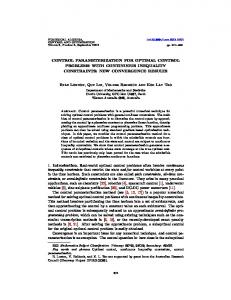
other facing the calyx region, and to acquire images using a single camera above the mirrors (Reese et al., 2007). There is a long history of attempts to orient apples (Stout et al., 1971; Carlson, 1987; Throop et al., 2005; Whitelock et al., 2006). Unfortunately, the commercial impact of orientation systems continues to be limited due to mechanical complexity, cost, error, or some combination thereof. We have discovered that the inertial properties of apples can be used to orient apples (Tasch et al., 2006). Results show that when apples are rolled down a track consisting of two parallel rails, the apples tend to move to an orientation where the stem/calyx axis is perpendicular to the direction of travel and parallel to the plane of the track (fig. 1; Narayanan et al., 2007). Theoretical analyses of axially‐symmetric objects subject to rotation support the hypothesis that the orientation phenomenon is a function of inertial properties and indicate that the distance an apple travels down the track before orientation occurs will be effected by factors including apple size, shape, and initial orientation (Narayanan et al., 2006). In addition, empirical tests suggest that track flexibility plays an important role in the orientation process. Another consideration is the increasing magnitude of precession effects as angular velocities increase. Precession can cause the stem or calyx to appear to rotate around the actual axis of rotation in a manner analogous to the rotation of a spinning top. Thus, while results of preliminary tests of the use of inertial properties to orient apples are promising, questions remain concerning implementation and viability of this orientation technology in a commercial setting. The first objective of developing an automated video acquisition system was to enable visualization of the orientation process. The second objective of developing analyses software was to allow quantification of measures reflective of the hypothesized dynamic principles underlying the orientation process. Specific goals were to locate the apple, to determine the location of the stem or calyx relative to the center of the apple, and to determine the amplitude of deflections of the track relative to a given x, y coordinate location as a function of time. To validate the commercial viability of using inertial properties to orient apples will require trials with hundreds, or even thousands, of apples. The development of an automated process that meets the stated objectives would greatly facilitate such endeavors.
Figure 1. Collage of sequential images taken at 0.1‐s intervals as an apple rolls down a test track. As angular velocity increases, the apple can be seen to move from an initial position with no specific orientation to an oriented position where the stem/calyx axis is perpendicular to the direction of travel and parallel to the plane of the track.
124
MATERIALS AND METHODS CAMERA AND IMAGE ACQUISITION A frame‐grabber (Model PCI‐1409, National Instruments, Austin, Tex.) was used to acquire individual image frames from a monochrome camera (Model XC‐HR50, Sony USA, New York, N.Y.) with an 8.5‐mm lens (Cosmicar, Asahi Optical Co., Tokyo, Japan). Image acquisition used an ActiveX Control (CWIMAQ, National Instruments) to set the gain and bias of the analog to digital converter (10‐bit resolution), to set the image window, and to transfer individual images to digital arrays. Software written in Visual Basic 6 (Microsoft, Seattle, Wash.) converted sequential image arrays into movies in AVI format. Non‐interlaced, full‐frame (640 × 480 pixels) images were acquired at 60 frames per second (fps) using an exposure time of 1/500 s. A photoelectric sensor (Model PZ‐M51P, Keyence, Woodcliff Lake, N.J.) attached to a digital I/O board (Model PCI‐DIO24, Measurement Computing, Norton, Mass.) was used to trigger image acquisition cycles. The sensor was attached to the I/O board using a connection box (Model SSR‐RACK08, Measurement Computing) containing a DC sense module (SSR‐IDC‐05, Measurement Computing). LIGHTING AND BACKDROP Two 300‐W and two 500‐W halogen lights (Model Tota, Lowell, Brooklyn, N.Y.) were mounted on two light stands (Promaster LS‐3, Photographic Research Organization, Inc., Fairfield, Conn.). A Chroma‐Key Green backdrop (10 × 12 ft; Botero, Bogotá, Columbia) was mounted on a background support system (Model SP93, Lowell), and the narrower (3 m) dimension of the backdrop was used as the width with the height set to 2.4 m. The excess backdrop material formed a 3 m wide × 1.2 m deep base on the floor. The two light stands were placed at the outer corners of this base with the 500‐W lamps about 1.5 m above the track. The 300‐W unit at the start of the track was placed about 0.5 m below the track and the unit at the end of the track was placed as close to floor level as possible. The camera was centered about 6.6 m from the track. APPLES AND TEST TRACKS Red Delicious, Golden Delicious, and Smokehouse apples were purchased from a local orchard. These three varieties were selected to represent a comprehensive cross‐section of apple shapes. Test tracks 3 m (10 ft) in length were constructed using a variety of standard wooden moldings for rails. Generally, wooden crossbars about 150 mm wide and 4 mm high were used to join the rails at 610‐mm (2‐ft) intervals. The distance between rails varied from 40 to 50 mm. To allow effects of track stiffness to be investigated two modifications were tried. First, the crossbars were replaced by a solid wooden board. Second, the wooden rails were replaced by metal “L” shaped rails. It should be noted that a number of tracks had to be discarded or rebuilt due to bends or bumps introduced during the building process or as a result of changes in the molding due to drying effects. Another factor that was varied was track inclination. A foam‐lined box was used to capture rolled apples. As some test conditions resulted in apples leaving the track, a gutter was subsequently added to hold the track and to return errant apples to the track (fig. 2). The track was raised from the bottom of the gutter using spacers at both end of the gutter and
APPLIED ENGINEERING IN AGRICULTURE
was loosely attached only at the top using a pin attached to the spacer and a hole in the top crossbar of the track. SOFTWARE DEVELOPMENT Software for analyses was written using Visual Basic 6 and an existing software library developed in‐house. The library includes routines to merge images into an AVI format movie and to extract a selected movie frame as an image. The library also supports a range of image manipulations (e.g., brightness, contrast, normalization, exponential scaling, linear combination of images, and ratios of two images) and filters (e.g., spatial, geometric, morphological, edge, and threshold; Weeks, 1996). The software allowed raw or transformed image data to be viewed as images, false color images, or histograms.
RESULTS AND DISCUSSION CREATING MOVIES The elapsed time as an apple rolled from the start to the end of a 3‐m track was about 1.2 s and it was hard to discern details of the orientation process in real‐time. To address this dilemma, image acquisition software was modified to allow sequentially‐acquired images to be saved as a movie using the AVI file format. This format was chosen for movies because it allows playback timing to be set explicitly in the file header. Thus, by adjusting the file header, playback can be slowed as desired. The ability to change the time‐base for AVI movie playback is incorporated in many video programs including Windows Media Player (Microsoft). The major problem encountered during the development of movie software was that the AVI frame array format is the inverse of the format used by the ActiveX routine used to acquire frame images. This problem was resolved by turning the camera upside‐down; however, the left‐right direction was reversed in resulting movies. An option was added to the analysis software to flip the horizontal axis. The default setting for movie creation was to set the playback rate to six frames per s, or 1/10 normal speed.
LOCATING APPLES IN MOVIE FRAMES The first attempt to locate apples in individual movie frames compared frames with an apple in it to a frame acquired after the apple had rolled off the track. Unfortunately, the movement of apples as they progressed down a track generally caused the track to oscillate. This oscillation created artifacts that made it difficult to determine the centroid of an apple in an individual frame. In any case, it is theoretically impossible to determine the true centroid of the apple as the track masks the bottom portion of apples. As identification of the true centroid is impossible, it was decided that it would be easier to identify apples if only a region above the track was used for comparisons. A mask of this region was created by locating the coordinates of the top of the track in a frame where the apple was absent; at 10 points equally spaced along the x‐axis, corresponding y‐coordinates were identified by starting at the top of the frame and progressing downward until the difference in intensity of two sequential points exceeded a user selected threshold. These 10 coordinates were then fit to a linear equation using the method of least squares. The resulting equation, shifted up 3 pixels to allow for track oscillation, was used to define the mask that was then used to detect the location of the apple in an image (fig. 2). The apple was located by taking the masked image, which included a portion of the apple, and subtracting a similarly masked image where the apple was not present. After applying a threshold, the x‐ and y‐coordinates of remaining pixels were averaged to determine the centroid of the visible portion of the apple. To estimate the location of the true centroid of the apple, user selectable x‐ and y‐offsets were added to this centroid of the visible portion of the apple. To allow users to select appropriate offsets and to confirm the validity of selected offsets, a 4x magnified window was overlaid on the original video where the estimated apple centroid for each frame was the center of the window. Thus, if the offsets were selected appropriately, the magnified apple in each frame appears in the center of the window. All magnified windows were smoothed by linear interpolation. In addition, each movie frame was modified so that the intensity of the pixel corresponding to the estimated apple centroid was changed to white (fig. 3). Once offsets were
Figure 2. Only the top portion of the raw frame image (a) was used to locate the apple (b). The track in this frame was a metal track inside an unpainted wooden gutter that gently returns errant apples to the track.
Vol. 24(1): 123‐129
125
Figure 3. Example of a single frame produced by the automated movie analysis software, which shows: (a) a magnified window centered on the estimated centroid of the apple, (b) a magnified window centered on the x, y‐coordinate location used as a reference to monitor track movement, (c) the apple on the track with a white dots showing the estimated apple centroid and the points at the edge of the track used to estimate the track location, and (d) the amplitude of the track as a function of time. In this example, the apple is almost at the center of the location used as a reference to monitor track amplitude.
determined using a single movie, the values could be used for all subsequent movies until the track was repositioned. However, a new equation for masking had to be calculated for each movie due to subtle shifts in track location. To allow for more detailed analyses, values of offsets and centroid coordinates were written to a comma delimited file along with values for track location and coordinates for the stem or calyx. CALCULATING THE AMPLITUDE OF TEST TRACK MOVEMENT (OSCILLATION) When it was realized that track flexibility impacted the ability to detect the centroid of apples in movie frames, it was decided to test the effects of using stiff tracks. Unfortunately, results were less than satisfactory. Apples commonly have irregularities in shape and problems related to these irregularities seemed to be accentuated when track stiffness was increased. For example, with stiff tracks, there was a tendency for apples to fly‐off the track. An apple has two points of contact with a track. Thus, as the apple rolls down the track, the two points of contact result in two effective “circumferences” of the apple interacting with the track. For many apples, the effective circumference nearer the stem is larger then the circumference nearer the calyx. This difference in effective circumferences means that there must
126
be some differential slippage to enable the apple to rotate around the stem/calyx axis as it rolls down the track. We hypothesize that a flexible track can better mitigate the negative effects of unbalanced forces related to slippage as compared to a stiff track. Furthermore, for some apples, at least one of the effective circumferences may not be round. This is particularly true of many Red Delicious apples where the effective circumference near the calyx end can have flat regions and sharp edges. In the extreme case, the cross‐section near the calyx end can be rectangular. Again, we hypothesize that the flexible track is better able to deal with the forces generated by these irregularities. The problem of apples leaving the track was addressed by adding a gutter around the track (fig. 2). A more troubling possibility is that use of stiff rails would increase the magnitude of instantaneous forces to which apples are subject and thus increase the chances of bruising the apples. To allow more detailed examination of the role of track flexibility in the dynamics of the orientation process, it was decided to incorporate a measure of track movement in the analyses software. Thus, a software procedure was written to allow track amplitude at a selected x coordinate to be quantified on a frame‐by‐frame basis. Vertical pixel resolution limits the precision for direct measurement of the vertical location of the track edge at a given x‐coordinate. However, it is possible to increase the accuracy and precision
APPLIED ENGINEERING IN AGRICULTURE
of estimates of this vertical location by using an averaging function that incorporates direct measurements of the vertical track‐edge locations at a number of surrounding x‐coordinates. For the selected x‐coordinate and 20‐pixel coordinates before and after this coordinate, the corresponding vertical coordinates at the top edge of the track were identified by looking at changes in intensity along the appropriate vertical column. The resulting x, y‐coordinate pairs were then fit to a linear equation using the method of least squares. This equation in essence corresponds to the localized top edge of the track. To refine this equation, the two x, y‐coordinates that deviated the most from estimated values as well as any coordinates that deviated from estimated values by more than 1.5 were identified, and the equation was recalculated with these points excluded. The equation was then refined a second time with no default exclusions and an error limit of 0.75. To allow visualization of results, the intensity at x, y‐coordinates used to calculate the final equation were set to white, and a 4x magnified window centered on the reference x, y‐coordinate location was overlaid on the original frame image (fig. 3). In general, points were excluded from calculations due to error only when the apple was near the selected x‐coordinate, as discussed below. To establish a reference coordinate system by which to measure the amplitude of track movement, the estimated linear equation for a frame where the apple was not on the track and the perpendicular line that passed through the selected x coordinate and the corresponding estimated y coordinate was determined. Amplitude in single frames was measured with respect to this perpendicular line; i.e., track amplitude in a given frame was calculated by determining the distance between the selected x, y‐coordinate location and the coordinates of the intersection of the estimated linear equation and the equation for the perpendicular line. Amplitude as a function of time was overlaid on the original frame towards the bottom of the frame (fig. 3). The major challenge for measuring track location occurs when the apple transverses, and thereby obscures, the track edge as it passes by the selected x‐coordinate reference location. Shading of the track by the apple reduces the contrast between the apple and the track, making it very difficult to detect the track edge. To address this dilemma, x‐coordinates normally represented in calculations of the estimate linear equation that were within 10 horizontal pixels of the x‐coordinate of the estimated apple centroid were excluded from calculations. To compensate for these excluded pixels, the range of x‐coordinates used to calculate the linear equation was expanded by the number of pixels excluded. The additional pixels were added so that the
number of pixels on each side of the selected x‐coordinate remained as balanced as possible. LOCATING THE STEM OR CALYX To locate the stem or calyx in a frame image, an exhaustive search was made within a radius of five pixels of the coordinates of the estimated apple centroid. No attempt was made to differentiate between the stem and the calyx. For each point within the search area, two tests were used to qualify the pixel at the test point as the potential center of the stem or calyx. First, the nine pixels surrounding the test point were examined to see if they are darker than corresponding outside‐adjacent pixels (fig. 4). To satisfy this test, seven of the nine possible comparisons must have been true. Second, the average intensity in the 3 × 3 area (9 pixels total) encompassing the center was compared to the average intensity of the 16 outside pixels. To satisfy this test, the average intensity of the area surrounding the center must have exceeded the average intensity of the center area by 10 (user selectable dependant on contrast in images). If more than one point (pixel) satisfied both tests, the one with the lowest corresponding center intensity was selected as the center of the stem or calyx. If no point satisfied both tests, it was assumed that there is no stem or calyx region in the frame image. An example of the result of using this detection process is shown in figure 5. TESTING PERFORMANCE OF SOFTWARE AND SUBSEQUENT PROBLEMS In tests using over 14000 frames, apples and the stem or calyx were successfully located with no false positives. There were a few false negatives concerning detecting the stem or calyx in frames the included the first or last occurrence of
Figure 4. To test if the point being qualified (black pixel) as the potential center of the stem or calyx is the center of a dark area, each corner point (c) is compared to see if it is darker than both corresponding outside‐adjacent points (1 and 2) and each middle point (m) is compared to see if it is darker than the corresponding outside‐adjacent point (3).
Figure 5. Sequential smoothed images of an oriented apple where the white pixel in each 25‐ × 25‐pixel image indicates the estimated centroid of the apple and the black pixel indicates, in this case, the center of the calyx. The rotation of the black spot around the white spot is presumably due to precession.
Vol. 24(1): 123‐129
127
the stem or calyx in a sequence of frames where the apple was oriented. The movie acquisition system and software were then used in a series of experimental trials and some deficiencies became apparent. The first problem that surfaced was the inability to detect the location of the apple in a small number of movies. Examination of these movies revealed that the apples had slid at least part way down the track. Almost all cases of this phenomena involved very small apples that got caught between the rails. The problem was that the apple was still on the track in the last frame of the movie, which created an error when that frame image was used as the background to detect apple locations. The software was modified to check to see if an apple was still on the track in the last frame by subtracting the masked first frame image from the masked last frame image and then looking at the portion of the image that contained the lower half of the track to see if an apple was present. The apple detection routine was modified to exclude consideration of the region extending from any detected apple to the end of the track. Similarly, the least‐squares estimation procedure used to create masks was modified to address the possibility that the edge of an apple was detected at one of the test coordinates rather than the edge of the track. The estimated linear equation was refined by recalculating the equation after excluding the coordinate pair with the greatest associated error. The second problem became apparent when a software routine was written to examine the degree of apple orientation by looking at factors such as the distance between the estimated centroid of the apple and the location of the stem or calyx, and the number of sequential frames where this distance was below a selected threshold. More specifically, a number of incidences where the stem or calyx was not detected were identified. It was determined that the detection problem was related to a number of factors with the main factor being poor lighting conditions. The use of the gutter introduced complications as it blocked illumination of the apple from below and the lower lights were raised to accommodate the gutter. The revised lighting scheme accentuated the existing intensity gradient from the top to the bottom of the apple. The gradient increased as a function of the distance the apple traveled down the track; i.e., the bottom of an apple received some illumination at the start of the track and little illumination at the end. The problem due to lighting were compounded by two additional factors. First, parallax reduces the effective horizontal resolution of the imaged area of the stem or calyx when the apple is at the beginning or end of the track. This problem was most evident when the stem or calyx faced away from the camera. Second, the magnitude of the difference in the distance between the axis of rotation of the apple and the stem or calyx tended to increase towards the end of the track, presumably due to precession effects resulting from increased angular velocity. Thus, when an apple was near the end of the track, the stem or calyx was often near the edge of the apple in images. d Under these condition, it was difficult to detect the stem or calyx when it faced down or away from the camera. Numerous strategies were tried to improve detection. The two most successful strategies were to lower detection thresholds and add a second test to see if the detected stem or calyx was really only a shadow, and to attempt to compensate for differences in
128
intensity gradients from the top to the bottom of the apple by adjusting detection thresholds. Neither strategy was 100% successful and combining strategies did not help. The best solution is to improve lighting. An alternative solution is to use outlier analyses to identify and remedy misclassifications, as discussed below. There were a number of other minor problems that were identified by looking at anomalies in data. The conclusion reached by this experience was not that the original software was deficient, but that the software and the experimental setup should be tuned and calibrated prior to experimental trials. As it was discovered that there was a complex interaction between lighting and detection thresholds, the software was modified to allow thresholds and acceptable error limits to be changed interactively using sliders or text boxes. Thus, movies can now be acquired with different lighting schemes and the robustness of detection tested by varying thresholds. In addition, the software originally designed to categorize degree of orientation was expanded to include the ability to look for outliers. A specific function was added that allowed a suspect frame to be viewed along with the prior and subsequent frames. This function was particularly useful for determining whether an apple should have been classified as oriented when the software detected the stem or calyx in surrounding frames but not in the current frame. In the experimental trails , results suggested that useful orientation occurred at the beginning of the track. Thus, the analysis software was modified to include a selectable frame cutoff value where errors in frames past the cutoff were ignored. Using this cutoff, errors in identifying the stem or calyx were found in less than 1% of movies and all errors resulted from unusual circumstances such as apples sliding rather than rolling. These results demonstrate that the performance of the video acquisition and analysis system can met the goals stated in the objectives of this study.
CONCLUSION Test results of the system developed to acquire movies of the apple orientation process, to determine the location and degree of orientation of the apple, and the location of the track in each movie frame clearly demonstrated the benefit of using the system for conducting future experimental trials. Use in actually experimental trials revealed potential sources of error, and the software was modified to address these potential errors. In addition, the system was modified to allow tuning and calibration of the system prior to use so as to eliminate most of the sources of these errors. Altogether, the software algorithms developed as part of this study should speed the design and assessment of practical systems for appropriately orienting apples for imaging.
REFERENCES Bennedsen, B. S., and D. L. Peterson. 2004. Identification of apple stem and calyx using unsupervised feature extraction. Transactions of the ASAE 47(3): 889‐894. Bennedsen, B. S., and D. L. Peterson. 2005. Performance of a system for apple surface defect identification in near infrared images. Biosystems Engin. 90(4): 419‐431.
APPLIED ENGINEERING IN AGRICULTURE
Brosnan, T., and D. W. Sun. 2004. Improving quality inspection of food products by computer vision - A review. J. Food Engin. 61(1): 3‐16. Brown, I. A., E. P. Ristow, and R. D. Walters. 1988. Roller for orientation of fruit. U.S. Patent No. 4,730,719. Washington, D.C.: Commissioner of Patents and Trademarks. Carlson, R. L. 1987. Apple orientation apparatus and method. U.S. Patent No. 4,706,797. Washington, D.C.: Commissioner of Patents and Trademarks. Chen, Y. R., K. Chao, and M. S. Kim. 2002. Machine vision technology for agricultural applications. Computers and Electronics in Agriculture 33(2/3): 173‐191. Kim, M. S., A. M. Lefcourt, Y. R. Chen, I. Kim, D. E. Chan, and K. Chao. 2002. Multispectral detection of fecal contamination on apples based on hyperspectral imagery: Part II. Application of hyperspectral fluorescence imaging. Transactions of the ASAE 45(6): 2039‐2047. Kleynen, O., V. Leemans, and M. F. Destain. 2005. Development of a multi‐spectral vision system for the detection of defects on apples. J. Food Engin. 69(1): 41‐49. Lefcourt, A. M., M. S. Kim, and Y. R. Chen. 2003. Automated detection of fecal contamination of apples by multispectral laser‐induced fluorescence imaging. Applied Optics 42(19): 3935‐3943. Lefcourt, A. M., M. S. Kim, and Y. R. Chen. 2005. Detection of fecal contamination on apples with nanosecond‐scale time‐resolved imaging of laser‐induced fluorescence. Applied Optics 44(7): 1160‐1170. Li, Q., M. Wang, and W. Gu. 2002. Computer vision based system for apple surface defect detection. Comp. Elec. in Agricult. 36: 215‐223. Mehl, P. M., Y. R. Chen, M. S. Kim, and D. E. Chan. 2004. Development of hyperspectral imaging technique for the detection of apple surface defects and contaminations. J. Food Engin. 61(1): 67‐81. Narayanan, P., A. M. Lefcourt, U. Tasch, R. Rostamian, A. Grinblat, and M. S. Kim. 2006. Theoretical aspects of orienting fruit using stability properties during rotation. ASABE Paper No.: 061144. St. Joseph, Mich.: ASABE.
Vol. 24(1): 123‐129
Narayanan, P., A. M. Lefcourt, U. Tasch, R. Rostamian, and M. S. Kim. 2007. Tests of the ability to orient apples using their inertial properties. ASABE Paper No. 076246. St. Joseph, Mich.: ASABE. Penman, D. W. 2001. Determination of stem and calyx location on apples using visual inspection. Computers and Electronics in Agriculture 33(1): 7‐18. Reese, D. Y., A. M. Lefcourt, M. S. Kim, and Y. M. Lo. 2007. Whole surface image reconstruction for machine vision inspection of fruit. SPIE Meeting Presentation. Boston, Mass. Paper No.: 6761‐25. Stout, B. A., D. H. Dewey, and R. F. Mrozek. 1971. Mechanical orientation of apples and related fruit characteristics. Michigan Agric. Exp. Station Research Bull. No. 32. Tasch, U., P. Narayanan, A. M. Lefcourt, M. S. Kim, A. Grinblat. 2006. Apparatus and method for orienting rotatable objects. U.S. Patent application No. 20060225582. Throop, J. A., D. J. Aneshansley, W. C. Anger, and D. L. Peterson. 2005. Quality evaluation of apples based on surface defects: development of an automated inspection system. Postharvest Biology and Technology 36(3): 281‐290. Weeks Jr., A. R. 1996. Fundamentals of Electronic Image Processing. Bellington, Wash.: SPIE Optical Engineering Press. Wen, Z., and Y. Tao. 2000. Dual‐camera NIR/MIR imaging for stem‐end/calyx identification in apple defect sorting. Transactions of the ASAE 43(2): 446‐452. Whitelock, D. P., G. H. Brusewitz, and M. L. Stone. 2006. Apple shape and rolling orientation. Applied Engineering in Agriculture 22(1): 87‐94.
129