Optical Engineering 49共3兲, 033607 共March 2010兲
Alignment procedure for radiation pattern measurements of antenna-coupled infrared detectors Peter M. Krenz, MEMBER SPIE Brian A. Slovick Jeffrey A. Bean Glenn D. Boreman, MEMBER SPIE University of Central Florida CREOL, The College of Optics and Photonics 4000 Central Florida Boulevard Orlando, Florida 32816 E-mail:
[email protected]
Abstract. An antenna-coupled detector’s directional properties can be verified by measuring its angular radiation pattern. At infrared frequencies, this pattern can be measured by rotating the device while illuminating it with a laser beam. An accurate radiation pattern can be measured only if the device is coaligned with the axis of rotation and the focus of the laser beam. In the alignment procedure presented, the device is rotated to various angles and the distance along the orthogonal axis from the current device position to the laser beam is measured by maximizing its response. Calculations based on these distances provide the new location of the device, which will coalign it with the axis of rotation and the focus of the laser beam. The successful alignment enables accurate radiation pattern measurements. © 2010 Society of Photo-Optical Instrumentation
Engineers. 关DOI: 10.1117/1.3365959兴
Subject terms: radiation pattern; alignment procedure; antenna-coupled detector; infrared antenna. Paper 090959 received Dec. 3, 2009; accepted for publication Feb. 1, 2010; published online Mar. 23, 2010.
1
Introduction
The concept of an antenna-coupled detector has been adapted from radio frequencies 共rf兲 to much higher frequencies. It was first demonstrated at infrared 共IR兲 frequencies,1,2 but it is also possible to use an antennacoupled detector at the near-IR3 and even the visible part of the spectrum.4 The antenna can modify the detector’s wavelength,5 directional,6 and polarization7 dependence. An angular map of its response, which is referred to as the radiation pattern, is used to validate the directional properties of the antenna design.8,9 The large dimensions of the antenna and measurement setup at rf frequencies make the alignment straightforward and positioning errors are generally small.10 At IR frequencies, the alignment must be more precise, since the dimensions involved are smaller. This paper outlines a procedure that can be used to align an antenna-coupled detector to measure its receiving radiation pattern. The device is mounted on a goniometer and is rotated while being illuminated by a stationary laser beam. The goniometer is computer controlled and enables the device to rotate and move relative to the incident beam. To measure an accurate radiation pattern, the device must be coaligned with the axis of rotation of the goniometer and the focus of the laser beam. This ensures that the rotating device is illuminated with the maximum irradiance at all angles of incidence. Descriptions of alignment procedures for optical systems typically follow two approaches. In both cases, a quantity is monitored from which information about the 0091-3286/2010/$25.00 © 2010 SPIE
Optical Engineering
optical system is gained. For instance, when aligning a laser diode to a fiber, the monitored quantity can be fiber optic coupling efficiency.11 The light diffracted past the sharp edge of the perimeter of a fiber12 can be monitored when aligning fiber segments to join them by splicing. For lenses or mirrors, the monitored quantity can be the ray aberration13 or wavefront errors.14 The first alignment approach adjusts the optical system iteratively, while minimizing the difference between the monitored quantity and its desired value. The second approach develops a theoretical description of the optical system based on the measured quantity. This theoretical description indicates how the optical system is misaligned. The system is then adjusted to remove the errors in alignment. The alignment procedure described here follows the second approach, in which the response and position of the device are monitored. The goniometer is used to rotate the device and then move it along orthogonal axes until it intercepts the beam, which will maximize its response. Based on these adjustments, we can determine how to move the device to coalign it with the axis of rotation. The goniometer is then moved so that the device and the axis of rotation are coaligned with the focus of the laser beam. Since the presented alignment procedure relies only on maximizing the device response, it can be applied to measure arbitrarily shaped radiation patterns.
2
Experimental Setup
The alignment procedure was developed to measure radiation patterns of IR antenna-coupled bolometers that were fabricated directly on the flat surface of a hemispherical
033607-1
Downloaded From: http://opticalengineering.spiedigitallibrary.org/ on 12/07/2014 Terms of Use: http://spiedl.org/terms
March 2010/Vol. 49共3兲
Krenz et al.: Alignment procedure for radiation pattern measurements…
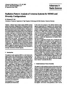
Fig. 1 Measurement setup showing goniometer and the focusing lenses.
silicon lens.9 A CO2 laser operating at 10.6 m is focused onto the device at F / 8. The device is mounted on a fiveaxis goniometer, which is shown in Fig. 1. Its position can be manipulated in x, y, and z as well as rotated and tilted about the center of the goniometer. The goniometer can be moved externally, both perpendicular or parallel to the laser beam, thus enabling the device to be positioned with eight degrees of freedom. Its movements are computer controlled, enabling precise positioning and monitoring of the device location. 3 Alignment Procedure A graphical representation of the top view of the goniometer is shown in Fig. 2. The rotational axis of the goniometer is represented as a cross at 共0,0兲. It forms the origin of the internal coordinate system along which the device can be moved and rotated about. The laser beam, propagating in the z direction, and its waist are shown. For the purpose of illustration, a large-diameter beam with exaggerated divergence is shown. Its focus is located at 共z f , x f 兲. The external goniometer movement will simultaneously reposition the axis of rotation and the device with respect to the focus of the laser beam. The device, indicated by the black square in Fig. 2, is mounted on the goniometer. The gray line shows the surface of the substrate on which the device is fabricated. It is
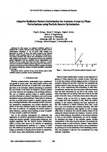
Fig. 3 Geometrical representation of device location with respect to the rotational axis for = ± a and = 0 deg for alignment of the internal z position. The device is offset in both the z and x directions.
parallel to the internal x axis and indicates the rotation of the device. In Fig. 2 the rotation is set to = 0 deg, and the position of the device is adjusted along the internal axes until its response is maximized. This occurs when the location of the device coincides with the focus of the laser beam, i.e., 共zd , xd兲 = 共z f , x f 兲.
3.1 Alignment Process for Internal z Axis At this point, the device is aligned only at = 0 deg. A radiation pattern measurement would not yield an accurate pattern, since rotating the device moves it away from the laser beam. A maximum amount of irradiance is illuminating the device only at broadside. The alignment process begins by removing the offset in the z direction between the device and the axis of rotation. Figure 3 shows the device, indicated as a square, located at 共zd , xd兲 for three different rotation locations: = ⫾ a, and = 0 deg. Since h+a = h−a, it can be shown that xm =
Fig. 2 Top view of the goniometer showing the axis of rotation, the device, the substrate surface, and the laser beam.
Optical Engineering
x +a + x −a 2
.
共1兲
If the device is positioned at 共zd, xd + xm兲 and rotated to either = −a or = +a, its response will be maximized when it is displaced along the internal z axis by −zd to its new location at 共0, xd + xm兲. In practice, the rotation is set to = 0 deg and the device is located at the focus of the laser beam. The goniometer is rotated to = +a and the device is adjusted along the internal x direction until its response is maximized. This occurs when the device intercepts the center of the laser beam and a maximum irradiance is falling on it. The direction and distance the device was moved is x+a. After restoring the device to its original position, the goniometer is rotated to = −a and x−a is determined. These two steps are illustrated in Fig. 4 for the case where a = 40 deg. The device location where its response is maximized is indicated by an asterisk. Both x+a and x−a are shown.
033607-2
Downloaded From: http://opticalengineering.spiedigitallibrary.org/ on 12/07/2014 Terms of Use: http://spiedl.org/terms
March 2010/Vol. 49共3兲
Krenz et al.: Alignment procedure for radiation pattern measurements…
Fig. 4 Determined position along the internal x axis to maximize response of device at 共a兲 = 40 deg and 共b兲 = −40 deg.
While still rotated to = −a, the device is moved by the distance xm, which is calculated using Eq. 共1兲. The device is located at 共zd, xd + xm兲, as shown in Fig. 5共a兲. The original device location is shown as a gray circle and the new location is marked by the black square. The device is now moved along the internal z axis until its response is maximized. As shown in Fig. 3, this corresponds to the distance −zd. The new device location, marked by a square, is 共0, xd + xm兲. Its previous position is indicated by a gray circle in Fig. 5共b兲. 3.2 Alignment Process for Internal x Axis The device is intercepting the laser beam at two angular locations, = ⫾ a. Now, the rotation of the device would move it in and out of the beam twice. At this point, the irradiance illuminating the device is still dependent on the angle of incidence and the measured radiation pattern is not accurate. Figure 6 shows the laser beam intercepting the device at = ⫾ a. The displacement of the device from the rotational axis is given by xd = xm
冉
冊
cos a . 1 − cos a
共2兲
The device is rotated back to = 0 deg, where it is moved along the internal x axis until its response is maximized. This distance is equal but opposite in direction to xm, which was calculated during the internal z axis alignment process. This is illustrated in Fig. 7共a兲. After completing this measurement, the device is moved back to its previous location 共0, xd + xm兲.
Fig. 5 Adjusting the 共a兲 x and 共b兲 z positions of the device. Optical Engineering
Fig. 6 Geometrical representation of device location with respect to the rotational axis for = ± a and = 0 deg for alignment of the internal x position. The device is offset only in the x direction.
Using Eq. 共2兲, xd can be calculated and the device is moved by −xd − xm along the internal x axis to its new position 共0,0兲. The device and the axis of rotation are coaligned as shown in Fig. 7共b兲. 3.3 Alignment Process for External Goniometer Position When the device is rotated, its position in space will no longer shift, since the device and the axis of rotation are coaligned. The final part of the alignment process is to move the axis of rotation along with the device to the focus of the laser. The goniometer is moved along its external x axis, repositioning the axis of rotation and the device relative to the laser beam, until the device response is maximized. This corresponds to a distance of x f , as shown in Fig. 8共a兲. The device has not moved relative to the axis of rotation and is therefore still located at 共0,0兲. The location of the focus is shifted to 共z f , 0兲. At this point, a radiation pattern can be measured. A small amount of defocus will not alter the shape of the radiation pattern. For example, displacing the device by ⫾1.3 mm along the z axis from the focus, which is 230 m in diameter, will still illuminate the device with 90% of the irradiance. This measured pattern is useful if only the shape of the radiation pattern is of interest. The magnitude of the response cannot be measured, since the actual irradiance on the device is not known. The goniometer is moved along the external z axis until the device response is further maximized. This occurs when
Fig. 7 共a兲 Determined position along the internal x axis to maximize response of device at = 0 deg and 共b兲 adjusting the device location to coincide with the axis of rotation.
033607-3
Downloaded From: http://opticalengineering.spiedigitallibrary.org/ on 12/07/2014 Terms of Use: http://spiedl.org/terms
March 2010/Vol. 49共3兲
Krenz et al.: Alignment procedure for radiation pattern measurements…
from the device to the laser beam was determined by maximizing the response. Using this information, we can calculated how to move the device to coalign it with the axis of rotation and the focus of the laser beam. This procedure was used to measure radiation patterns in Ref. 9, where good agreement with theoretical predictions is shown.
References Fig. 8 External goniometer adjustment along the external 共a兲 x axis and 共b兲 y axis.
the device and focus are coaligned. Figure 8共b兲 shows that the device, axis of rotation, and focus are located at 共0,0兲. If the device is rotated, it will remain in the focus of the laser, and a radiometrically accurate radiation pattern can be measured. The alignment procedure assumes that the goniometer and device can be moved perfectly parallel and perpendicular with respect to each other and the laser beam. In a lab setup, such precision is difficult to achieve, and the goniometer will be slightly tilted with respect to the laser. Consequently, if the position of the goniometer or the device is adjusted along the x or z direction, a small shift in the z or x direction will be introduced. After completing this alignment procedure, the axis of rotation, the device, and the laser beam will be nearly, but not quite coaligned. Repeating the procedure will minimize this error. When the device is mounted in the goniometer, a small amount of tilt could be introduced, causing the substrate surface on which the device is fabricated to not be parallel to the internal goniometer x axis. This misalignment has no impact on the alignment procedure and the device will be coaligned with the axis of rotation and the focus of the laser beam. However, the measured pattern will be tilted. This problem is solved by coaligning a visible HeNe laser with the CO2 laser. By observing back reflections, it is possible to ensure that the substrate surface is perpendicular to the laser beam and therefore parallel to the internal goniometer x axis. The CO2 laser power exhibits small fluctuations with time. During this alignment procedure, the device response is observed. The laser power fluctuations may cause the device to indicate a maximum response when it is not positioned at the center of the laser beam. In this case, a reference power meter should be used to monitor the power fluctuations. If the responsivity of the device is linear, the measured response can be divided by the reference power. This normalized response can be used throughout the alignment procedure.
1. L. O. Hocker, D. R. Sokoloff, V. Daneu, A. Szoke, and A. Javan, “Frequency mixing in infrared and far-infrared using a metal-to-metal point contact diode,” Appl. Phys. Lett. 12共12兲, 401–402 共1968兲. 2. S. E. Schwarz and B. T. Ulrich, “Antenna-coupled infrared detectors,” J. Appl. Phys. 48共5兲, 1870–1873 共1977兲. 3. L. Tang, S. E. Kocabas, S. Latif, A. K. Okyay, D.-S. Ly-Gagnon, K. C. Saraswat, and D. A. B. Miller, “Nanometre-scale germanium photodetector enhanced by a near-infrared dipole antenna,” Nature Photon. 2共4兲, 226–229 共2008兲. 4. C. Fumeaux, J. Alda, and G. D. Boreman, “Lithographic antennas at visible frequencies,” Opt. Lett. 24共22兲, 1629–1631 共1999兲. 5. M. A. Gritz, M. Metzler, M. Abdel-Rahman, B. Monacelli, G. Zummo, D. Malocha, and G. D. Boreman, “Characterization of a wavelength-tunable antenna-coupled infrared microbolometer,” Opt. Eng. (Bellingham) 44共3兲, 036402–036405 共2005兲. 6. B.-L. Twu and S. E. Schwarz, “Properties of infrared cat-whisker antennas near 10.6 m.” Appl. Phys. Lett. 26共12兲, 672–675 共1975兲. 7. C. Fumeaux, W. Herrmann, F. K. Kneubühl, and H. Rothuizen, “Nanometer thin-film Ni–NiO–Ni diodes for detection and mixing of 30 THz radiation,” Infrared Phys. Technol. 39共3兲, 123–183 共1998兲. 8. E. N. Grossman, J. E. Sauvageau, and D. G. McDonald, “Lithographic spiral antennas at short wavelengths,” Appl. Phys. Lett. 59共25兲, 3225–3227 共1991兲. 9. B. A. Lail, C. T. Middlebrook, P. M. Krenz, and G. D. Boreman, “Infrared dipole-coupled bolometer response on a hemispherical silicon immersion lens,” Infrared Phys. Technol. 52共2–3兲, 89–96 共2009兲. 10. “IEEE standard test procedures for antennas,” ANSI/IEEE Std. 1491979 共1979兲. 11. R. Zhang and F. G. Shi, “Novel fiber optic alignment strategy using Hamiltonian algorithm and MATLAB/Simulink,” Opt. Eng. 42共8兲, 2240–2245 共2003兲. 12. L. C. Brun, P. Bergeron, M. A. Duguay, F. Ouellette, and M. Tetu, “Optical fiber alignment using cleaved-edge diffracted light,” Opt. Eng. 32共8兲, 1819–1822 共1993兲. 13. M. A. Lundgren and W. L. Wolfe, “Alignment of a three-mirror offaxis telescope by reverse optimization,” Opt. Eng. 30共3兲, 307–311 共1991兲. 14. Z. Gao, L. Chen, S. Zhou, and R. Zhu, “Computer-aided alignment for a reference transmission sphere of an interferometer,” Opt. Eng. 43共1兲, 69–74 共2004兲.
4 Conclusion Measuring the receiving radiation pattern of an antennacoupled detector is one method to characterize the directional properties of the device. The detector must be aligned precisely, since at IR frequencies, the involved dimensions are small. A procedure was outlined, describing how to align an antenna-coupled detector to the rotational axis of a goniometer and the focus of a laser beam. The device was rotated to various angles, where the distance Optical Engineering
Peter M. Krenz received his BS degree in electrical engineering from the Oklahoma State University in 2003 and his MS degree in optics from the University of Central Florida in 2008. His is currently a graduate research assistant while working toward his PhD in optics at the College of Optics and Photonics 共CREOL兲 at the University of Central Florida. His research interests include the simulation, fabrication, and characterization of uncooled antenna-coupled IR detectors. Brian A. Slovick received his BS and MS degrees in physics from San Diego State University in 2005 and 2007, respectively. He is currently a PhD student in optics at the Center for Research and Education in Optics and Lasers 共CREOL兲 at the University of Central Florida. His research involves the design, fabrication, and measurement of IR antenna-coupled tunnel diodes.
033607-4
Downloaded From: http://opticalengineering.spiedigitallibrary.org/ on 12/07/2014 Terms of Use: http://spiedl.org/terms
March 2010/Vol. 49共3兲
Krenz et al.: Alignment procedure for radiation pattern measurements… Jeffrey A. Bean received his BS degree in electrical engineering from the University of Wyoming in 2003 and his MS and PhD degrees from the University of Notre Dame in 2005 and 2009, respectively. He is currently a postdoctoral research associate at the University of Central Florida, where he is conducting research on antenna-coupled metal-oxide-metal diodes for IR detection. His research interests include the fabrication and characterization of high-speed antenna-based IR detectors.
in Albuquerque, and FOI 共the Swedish Defence Reserch Agency兲 in Linköping, Sweden. He served 6 years as the editor-in-chief of Applied Optics and is currently an associate editor of Optics Express and the editor of the Wiley Series in Pure & Applied Optics. He is a coauthor of Infrared Detectors and Systems and the author of Modulation Transfer Function in Optical and Electro-Optical Systems and Basic Electro-Optics for Electrical Engineers. He is a fellow of the Military Sensing Symposium, OSA, and SPIE.
Glenn D. Boreman is Trustee Chair Professor of Optics at University of Central Florida, Center for Research and Education in Optics and Laser 共CREOL兲. He received his BS degree in optics from the University of Rochester and his PhD degree in optics from the University of Arizona. He has been a visiting scholar at Imperial College in London, the Swiss Federal Institute of Technology 共ETH兲 in Zürich, Complutense University in Madrid, the University of New Mexico
Optical Engineering
033607-5
Downloaded From: http://opticalengineering.spiedigitallibrary.org/ on 12/07/2014 Terms of Use: http://spiedl.org/terms
March 2010/Vol. 49共3兲