7.8
An 8x8 Run-Time Reconfigurable FPGA Embedded in a SoC Sumanta Chaudhuri, Sylvain Guilley, Florent Flament Philippe Hoogvorst and Jean-Luc Danger GET-ENST, CNRS(UMR 5141) 46 Rue Barrault,Paris, FRANCE
{
[email protected]} ABSTRACT This paper presents a RTR FPGA embedded in a System on Chip fabricated in 130nm CMOS process. Various aspects of the design flow, from automation to floor-planning are discussed. We explain the measures taken in the FPGA design to guarantee RTR functionality free of electrical conflicts, and we present a flow based on Altera synthesis tools to implement IPs(Hardware Blocks) in this FPGA. We demonstrate the full functionality with experiments on the FPGA, and as conclusion we highlight the limitations and future research directions.
Categories and Subject Descriptors B.7.1 [ HARDWARE]: INTEGRATED CIRCUITS—Types and Design Styles, Gate arrays
General Terms Design
Keywords FPGA, RTR
1.
a temporary short circuit which puts the system in an unknown state). Aspects at higher level are high reconfiguration speed, efficient utilization etc. Other aspects of FPGA design are automatic layout generation. Due to its repetitive structure, such automated flows are feasible, and greatly reduces the development time while providing the researcher with ample opportunity to experiment. By embedding an FPGA into a SoC, considerable cost saving and faster operation can be achieved since there are no IO pads required, and no external connections. This paper presents a fully operational fine-grain RTR FPGA ”FASE”(FPGA Architecture for Secure Embedded System) and its associated automatic design flow. In the rest of the article we are going to present our circuit in the following manner. Section 2 describes the automated design flow based on VPR [4, 5], and compares the results with previous efforts of the same kind, Section 3 outlines the system and the FPGA architecture, Section 4 presents the physical details, Section 5 explains the flow to implement an IP in the FPGA from the user point of view, Section 6 demonstrates the full functionality of the FPGA with an experiment.
2.
INTRODUCTION
DESIGN FLOW AUTOMATION
2.1
FPGAs have become increasingly popular over the past decade, on the other hand Run-time Reconfigurability enables FPGAs to be used as general purpose parallel computing devices, and/or Evolvable Hardware(EH). RTR FPGAs exist since quite a long time: from the earlier columnwise dynamically reconfigurable Xilinx devices to the latest Virtex-5 [10] which supports arbitrary run-time reconfigurability. However their present day and ever increasing logic capacity permits to map even complex algorithms in hardware, giving way to a new computing paradigm. Arbitrary Run-time Reconfigurability has several interesting and challenging aspects. At the physical level, it is to guarantee a functionality free of electrical conflicts (e.g
Permission to make digital or hard copies of all or part of this work for personal or classroom use is granted without fee provided that copies are not made or distributed for profit or commercial advantage and that copies bear this notice and the full citation on the first page. To copy otherwise, to republish, to post on servers or to redistribute to lists, requires prior specific permission and/or a fee. DAC 2008 June 8–13, 2008, Anaheim, California, USA Copyright 2008 ACM 978-1-60558-115-6/08/0006 ...$5.00.
120
Design Flow
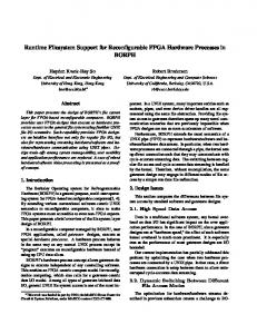
As illustrated in figure 1, our FPGA design flow has a single entry point, namely the architecture file (format VPR). To fully exploit the capabilities of VPR as a FPGA modeling tool, and not as a mere Placer/Router, VPR has been modified to generate a VHDL structural model as a one to one mapping from its internal routing graph. The input to the automatic layout generator is the structural VHDL generated by VPR, so it can handle FPGAs that can be modeled with VPR.
2.2
Automatic Floorplan
Our layout scheme is divided in two parts. Firstly the routing matrix which consists of square switch-boxes and routing channels repeated over space, and secondly the rectilinear Configurable Tiles (CLB + Connection Boxes) (see fig. 4) superimposed on this routing matrix. These steps are automated using Tcl/Perl scripts running on CADENCE SoC-Encounter P/R tool. The automatic layout generator in figure 1 works in the following manner : • First the switches inside the switchboxes are placed and routed and a switchbox library is built. Nine different switchbox types (4 side + 4 corner + centre)
ARCHITECTURE FILE
VPR ROUTING GRAPH STRUCTURAL VHDL RTL MODELS ( lbs , swit hes) Bitstream
VHDL SIMULATOR Fun tional Simulation SDF Annotate
Bitstream
VHDL SIMULATOR
COMPONENT LIBRARY
synthesis
AUTOMATIC FLOORPLAN PLACE/ROUTE (SILICON) CLOCK TREE LAYOUT TIMING VERIFICATION DRC + LVS MASK
DELAY
In Cir uit Simulation
(a) W=16, 20x20, SIZE 2577.6700 µm BY 2125.4400 µm
TIMING ABSTRACT
Bi ts
tr
ea m
CT NORTH
CT WEST
LEGEND EQUIVALENT FLOW
CT EAST CT CENTRE
Figure 1: FPGA design flow. are placed and routed. We use the same size for all of them because the FPGA area is mainly dependent on the centre switch box size. The routing channel ports are aligned for each switch box. These switchboxes are then placed inside the FPGA. • Next the CTs as described in figure 4 are placed and routed. Their rectilinear dimensions are dependent on switchbox dimensions previously calculated. There are 5 different types of CTs (4 side + centre), as shown in figure 2(b). • clock tree synthesis: To insert the clock tree buffers we left small slices in between the configurable tiles and switchboxes. This slice size is estimated in two passes. For the first pass all tiles are placed, and clock tree is synthesized. In the next pass all tiles are replaced with appropriate gaps between them, to insert clock tree buffers. A ’H’ clock tree is generated automatically using SoC-Encounter. • The configuration signals are routed automatically by ASIC layout tool(SOC-Encounter) in the top metal layers. A note for architectures with long lines. Long lines are used in a staggered fashion to enhance the routability. Due to this staggering, switchbox patterns repeat themselves with a period equal to the length of the long lines. In cases where different lengths are used the period is the LCM of these lengths. In our flow, since the VHDL code generated is an exact replica of the routing graph, each switchbox is described individually, and can be laid out exactly as it is seen by the modelling tool(VPR). However for bigger FPGAs this could become excessively time consuming for tools that handle this detailed VHDL code. To avoid that, once the VHDL code is generated, we only keep the useful part and repeat
121
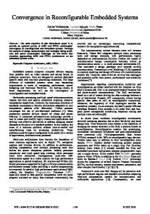
SBOX CT SOUTH (b) W=5, 5x11, SIZE 620.7400 µm BY 885.6000 µm Figure 2: Examples of automatically generated layouts in 130 nm. it with a frequency equal to the LCM of the lengths. The Logic element and connection box patterns are the same, and hence it can be repeated with a frequency of 1. More details about simulation, rectilinear floorplan etc. can be found in [8]
2.3
Comparison with Previous Works
Reference [7] describes an automated FPGA layout generator(GILES) based on VPR. To compare it with our approach, we generate the layout using the same architecture described in [7]. This GILES reference architecture has been laid out with 180nm, so we scale it down to 130nm and do the comparison(see table 1). While comparing it should be kept in mind that the basic cells used are considerably different. While Giles used SRAM cells, we have used D Flip-Flops as our basic configuration point. We also point out the difference in the size of buffer switches used in both cases in table 1. Figure 2 shows two example floorplans generated with our flow in 130nm process. W is the channel width used, and units are in microns.
Table 1: Comparison with the GILES Reference Architecture. Flow
Tile Area
Tech nology
Giles Flow Giles Flow
48,282 µm2 24,141 µm2
180nm
Switch Memory Memory Area cell cell type Area 18.30 4x4 13.07 µm2 SRAM µm2 9.15 4x4 6.53 µm2 SRAM µm2
130nm (Tech-
(Tech-
nology
nology
Scaled
Table 2: Architectural Parameters LUT Size 4 Cluster Size 1 Channel Width 5 Channel Length 1 Track switches Transmission Gate SwitchBox Type Wilton Fcinput 0.5 Fcoutput 0.5 Fcpad 1 Array Size 8×8 IO Pads/Row or Column 1
)
scaled)
Our Flow
28,009 µm2
130nm
SECMAT FASE CONF
14.12 µm2
CONF SIGNALS FASE ARRAY
D FF
40.3 µm2
DES
VCI WRAPPER
VCI WRAPPER
VCI WRAPPER
VCI INTERFACE
VCI INTERFACE
VCI INTERFACE
VCI INTERFACE
VCI INTERFACE
VCI INTERFACE
VCI WRAPPER
VCI WRAPPER
VCI WRAPPER
CRYPTO IP 1
FREE6502
CRYPTO IP 2
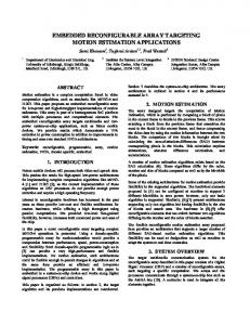
Figure 3: VCI interface for FASE_ARRAY and FASE_CONF.
3. 3.1
ARCHITECTURE FASE Overall Architecture and Principles
FASE is embedded in our SoC ”SECMAT” dedicated to secure cryptographic hardware. It comprises of various IPs on the VCI bus with the processor FREE6502 serving as the master. As an embedded FPGA, FASE is designed to be connectable to a system bus. It thus features a VCI [1] interface. Each module on the VCI bus is Equipped with an interfacing block and it’s own RAM. This RAM can be used by the module or it can be read/written by the master, the open source processor FREE6502 in our case. The general architecture of FASE comprises of a functional array (FASE_ARRAY) and of a configuration controller (FASE_CONF), as shown in figure 3. FASE_ARRAY and FASE_CONF are connected through signals dedicated for configuration. In the next section we discuss the FASE_ARRAY or the FPGA architecture and later we will present the configuration controller.
3.2
FASE_ARRAY
Our design flow is based on VPR, hence we use the VPR nomenclature for describing the architecture. The major architectural parameters are described in table 2. These parameters and their effect on the FPGA performance are discussed in detail in [4, 5]. LUT Size and Cluster Size are chosen to be that of a basic FPGA(no clustering). And channel width is chosen to be 5 since this is a small FPGA. Channel length of 1 results in an uniform architecture(i.e no staggered segments). Since this is a prototype to validate run-time reconfigurability we have chosen a simple architecture. The choices available for routing switches are Pass Tran-
122
sistor, Tri-State Buffer and Transmission Gate. While pass transistors are bi-directional, they degrade the output level. Buffers are fast, since it is an active switch. They are bigger and directional. For RTR buffers are problematic, since their output is undefined when the input is high impedance. Which can occur frequently during reconfiguration. We have chosen Transmission gate for it’s small size and no level degradation. Switchbox architectures are well discussed in literature [4, 9]. The Wilton architecture has the advantage that it doesn’t create any domains within the routing fabric, and leaves the router with more options. The other parameters Fc are chosen based on study already available [5]. The logic element (LE) is composed of a look-up table (LUT) and a D-flip-flop (DFF), and features reset mask RST_MASK which indicates whether the DFF reset line is active or not. More detailed description of this architecture can be found in [6].
3.3
RTR Features
• The organization of FASE can be divided into two hierarchies, namely the The set of configurable tiles (CT), and the Routing Matrix. – The configurable tile (CT), depicted in figure 4, is composed of one CLB plus, at its periphery, the following switching components: The connection box CBOX_IN (resp. CBOX_OUT) permits the CLB input (resp. output) connections. – the Routing Matrix comprises of the routing tracks and the the switch boxes (SBOX) A RTR IP in FASE is a set of CTs that hooks on to the Routing Matrix to form a circuit, by means of its’ connections boxes. • RST_MASK: this configuration bit allows selective initialization of CTS. This is convenient for RTR since we might not want to disturb the set of CTs belonging to other IPs which are in functional mode. • Inside a CT, there are four configuration chains selected by the signals ADDR_INTRA_CT[1:0]. Each chain corresponds to specific CT components: .
CBOX2 IN
CBOX2 OUT
W CBOX3 OUT
CLB
CBOX1 IN
CLB(i, j) A tive
CBOX3 IN
CBOX4 IN
CBOX4 OUT
RST MASK
CBOX1 OUT
swit h matrix
Conne tions(i, j) A tive.
(SBOX)
Figure 4: The configurable tile (CT) and its components. 1
M0 | M15
set
... a(3..0)
4
LUT
DFF
CLK RST
lear
RST MASK
...
...
...
CLB(i+1, j) Can be re on gured w/o interrupting CLB(i, j) ... Conne tions(i+1, j). Can be re on gured w/o interrupting
onne tions(i, j)
Figure 7: Input connection box: granularity of configuration (W=4, fc in=fc out= 12 ).
y
Table 3: Physical Details. Die Size(SoC) 4.1mm2 Area(FASE ARRAY) 0.6mm2 Transistor Count 200,000 (Approx.) Vdd 1.2V Vdd IO 1.2V Fmax 32MHz
SEQ/COMB
set
lear
SET/CLEAR
Figure 5: CLB comprised of (only) one 4 → 1 LE with maskable reset.
3.4
Configuration
The configurable memory points are programmed via a set of shift registers inside each CT. From a configuration viewpoint, an IOB is considered as being a CT subset. This is because the IOB has no CLB and the number of CBOX and SBOX depends on the IOB location. At power up, the power on reset signal (denoted PO_RST) permits to start with all the configuration points inactive.
3.4.1
Configuration Architecture CONF DATA
CONF CLK ADDR ROW ADDR COL
or operation interrupt. The chain input is CONF_DATA and the chain clock is CONF_CLK. Figure 6 depicts the architecture of the four configuration chains. The output connection boxes use tri-state buffers rather than pass-transistors to allow high fan-out drive. Figure 7 shows the connection box configuration points. If we consider one LE per CLB, the number of configuration points as in figure 5, the number of configuration points is as follows: • CLB: 18 (M0 – M15, SEQ/COMB, SET/CLEAR),
Chain 0: CBOX1 OUT+CBOX2 OUT+CBOX3 OUT+CBOX4 OUT Chain 1: CBOX1 IN+CBOX2 IN+CBOX3 IN+CBOX4 IN+CLB Chain 2: SBOX RST MASK
ADDR INTRA CT[1:0℄
Figure 6: Separately addressable configuration chains of FASE. In FASE, each CT and IOB is addressable by the ADDR_ROW and ADDR_COL lines. Inside a CT, there are four configuration chains selected by the signals ADDR_INTRA_CT[1:0]. Each chain corresponds to specific CT components: To avoid electrical conflicts due to shifting of configuration bits along the chain, the CBOX_OUT is disabled during the CT configuration period, except if the RST_MASK is being configured. This will allow the designer to split dynamically active blocks and inactive blocks without any conflict
123
• RST_MASK: 1, • CBOX_IN: (W × Fc in) × number of inputs, • CBOX_OUT: (W × Fc out) × number of outputs, • SBOX: 6 × W, where: W is the number of tracks per row or column, Fc in and Fc out are respectively the flexibilities of the CBOX_IN and CBOX_OUT. The configuration controller gives access to all the operations described in this section through a set of simple instructions. More details about these instructions and the configuration sequence can be found in [6].
4.
IMPLEMENTATION DETAILS
Figure 8(a) shows the micrograph of the SoC SECMAT. All the components on the VCI bus are highlighted. The configuration controller is in the glue logic around FPGA. The small highlighted block are the RAMs for each VCI module, VCI interface is in the glue logic. Our circuit have been fabricated with ST Microelectronics 130nm 6-layer process(CMP run SI2C7 1). Various physical details about the FPGA are listed in table 3. Although the configuration circuitry in the FPGA has been designed to operate at 66MHz, we have tested the correct functionality upto 32MHz.
(a) SoC micrograph, eFPGA in the upper left corner
(b) Test Setup
Figure 8: SoC and Test Setup. is a lex/yacc based parser. We added one more field to the VPR netlist format which contains the bitstream for each CLB. After place/route the modified VPR generates the bitstreams as a set of instructions for FASE_CONF.
entity MMU is generic(NA:integer:=8...; port( ADDR:out std_ DI:in std_ulog DO:out std_u. WE:out std_ulogic; START:in std_; EOC:out std_ ... ...
6.
stratix_lcell \n[3]~I ( .clk(CLK), .dataa(\n[0]~54 ), .datab(\n[3] ), .datac(\state.write ), .datad(\Equal0~36 ), .aclr(__ALT_INV__RST), .regout(\n[3] )); defparam \n[3]~I .operation_mode = "normal"; defparam \n[3]~I .synch_mode = "off"; defparam \n[3]~I .register_cascade_mode = "off"; defparam \n[3]~I .sum_lutc_input = "datac"; defparam \n[3]~I .lut_mask = "2888"; defparam \n[3]~I .output_mode = "reg_only";
• IP1: Does a cyclic Vernam cipher (Xoring the message with a pre-defined key) with the 256 bytes in the RAM. The key is stored in the IP itself. • IP2: A 24 bit counter, which stores the count value in the RAM.
.clb \n[3]~I config: 0000000000011110010 pinlist: \n[0]~54 \n[3] \state.write \Equal0~36 \n[3] CLK subblock:\n[3]~I 0 1 2 3 4 5
The goal of this experiment is to validate the correct functionality in presence of run-time reconfiguration and to find out the bottlenecks of such systems. The experiment itself consists in
.clb \Equal0~37_I config: 0000000000000001000 pinlist: \n[0] \n[1] \n[2] \n[3] \Equal0~37 open subblock:\Equal0~37_I 0 1 2 3 4 open
SET_ROW 1 SET_COL 1 CONFIG_CLB_CBOX_IN SET_ROW 2 SET_COL 1 CONFIG_CLB_CBOX_IN SET_ROW 3 SET_COL 1 CONFIG_CLB_CBOX_IN SET_ROW 4 SET_COL 1 CONFIG_CLB_CBOX_IN SET_ROW 5 SET_COL 1 CONFIG_CLB_CBOX_IN
000000001111111
• First configuring IP2 into the FPGA.
000000001111111
000000000000111
• During the execution of IP2, partially configuring IP1 into the CTs that are not used by IP2.
000000001111111
10000000011010
• Once IP2 finishes, erase IP2, full configuration and execution of IP1 .
Figure 9: IP design flow. Figure 8(b) shows the test setup for our SoC SECMAT. All the input/outputs of SECMAT are controlled by an interfacing card with on board Linux [3]. Programs are downloaded into SECMAT via this card which is connected to Ethernet. Each VCI module in SECMAT has its own power supply pins for accurate power measurements.
5.
EXPERIMENT
The dynamic IPs concerned are
IP DESIGN FLOW
The design flow to develop user IPs are outlined in figure 9. Our flow is based on industry standard Altera [2] synthesis tools. The VQM netlists generated by Quartus synthesis are transformed to the VPR net format with vqmtonet which
124
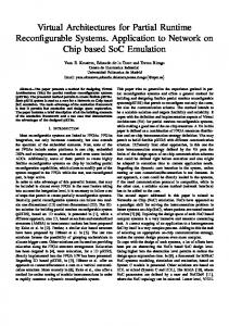
• Verify that the results are correct. Table 4 provides the various details of this experiment. Figure 6 illustrates the various steps of the experiment. In Fig 10(a) the places marked with cyan means both the CLB, inputs and the switchbox are being configured, red means only the CLB and inputs are being configured. The difference in reconfiguration time and Erase Time is due to the fact that, while erasing only the output connection of CLBs are erased to avoid any short circuit during reconfiguration. After that, the configuration for input connection boxes, CLBs and Switch Boxes are overwritten with the new configuration.
EOC
WE
CLK
1’b0
1’b1
EOC
WE
CLK
1’b0
1’b1
EOC
DI[0]
DI[0]
DI[0]
DI[1]
DI[1]
DI[1]
DI[2]
DI[2]
DI[2]
DI[3]
DI[3]
DI[3]
DI[4]
DI[4]
DI[4]
DI[5]
DI[5]
DI[5]
DI[6]
DI[6]
DI[6]
DI[7]
DI[7]
DI[7]
Routing succeeded with a channel width factor of 5.
Routing succeeded with a channel width factor of 5.
(a) IP2 in execution and IP1 CLBs & switchboxes are configured (red n & cyan n).
(b) IP2 erased.
WE
CLK
1’b0
1’b1
Routing succeeded with a channel width factor of 5.
(c) IP1 functional.
Figure 10: Run-Time Reconfiguration of IP2 while IP1 is in execution.
Hardware Blocks
Table 4: Demonstration of RTR on 8x8 FPGA. No of CLBs Execution Time Reconfiguration Time LUT4+FF
IP1 IP2
7.
58 44
(Computation Cycles) 1024 67108864
(Computation Cycles) 3712 2816
CONCLUSION
This paper presents a fully operational RTR FPGA(8x8) embedded in a SoC. The key features of this FPGA are that it is generated through an automated design flow, and it’s capability to perform run-time reconfiguration free of electrical conflicts, which is demonstrated through an experiment. The advantages and disadvantages of the design flow automation are discussed and the results are compared with previous efforts of the same kind. We also present the user design flow which is very convenient, since it uses industry standard Altera synthesis tools along with VPR for place/route and bitstream generation. Although commercial FPGAs like Virtex-5 offer RTR capability, the open nature of this project and access to the design flow allows the user to fine tune the FPGA according to his/her requirements(e.g in our case we added a functionality to selectively initialize each CLB). Our FPGA design flow is based on standard cell libraries, which permits the user to migrate easily to a newer technology, and experiment with various architectures. For the moment, this design flow is limited only to VPR-style architectures, Our future goal will be to enhance this flow to include various other type of architectures such as hierarchical FPGAs, and island style FPGAs with different tiling patterns (Octagonal, Hexagonal).
8.
REFERENCES
[1] Virtual Socket Interface Alliance – VCI Standard. http://www.vsia.org/. [2] Altera. Quartus Synthesis Tool.
125
Erase Time (Computation Cycles) 174 132
Reconfig Ratio Column III Column IV
0.276 23831.27
http://www.altera.com/, 2007. [3] Axis. Fox board, 2005. http://www.acmesystems.it/?id=4. [4] V. Betz and J. Rose. VPR: A New Packing, Placement and Routing Tool for FPGA Research. Int’l Workshop on FPL, pages 213–222, 1997. [5] V. Betz, J. Rose, and A. Marquardt. Architecture and CAD for Deep-Submicron FPGAs. Kluwer Academic Publishers, 1999. [6] S. Chaudhuri, J.-L. Danger, S. Guilley, and P. Hoogvorst. FASE: An Open Run-Time Reconfigurable FPGA Architecture for Tamper-Resistant and Secure Embedded Systems. In ReConFig 2006, September 2006. San Lu´ıs Potos´ı, M´exico, (http://www.tsi.enst.fr/publications/ enst/inproceedings-2006-6437.pdfOnline PDF). [7] I. Kuon, A. Egier, and J. Rose. Design, layout and verification of an fpga using automated tools. In FPGA ’05: Proceedings of the 2005 ACM/SIGDA, pages 215–226, New York, NY, USA, 2005. ACM. [8] Sumanta Chaudhuri and Jean-Luc Danger and Sylvain Guilley. Efficient Modeling and Floorplanning of Embedded-FPGA Fabric. pages 665–669, Aug 2007. FPL, Amsterdam, Netherlands. [9] S. Wilton. Architectures and Algorithms for Field-Programmble gate Arrays with Embedded Memories. PhD thesis, University of Toronto, 1997. [10] Xilinx. Virtex-5. http://www.xilinx.com/, 2007.