An Adaptive Hierarchical Next-Best-View Algorithm for 3D Reconstruction of Indoor Scenes Kok-Lim Low National University of Singapore
Anselmo Lastra University of North Carolina at Chapel Hill
[email protected]
[email protected]
Abstract We present a new and efficient next-best-view algorithm for 3D reconstruction of indoor scenes using active range sensing. To evaluate each view, we have formulated a general view metric that can include many real-world acquisition constraints and quality requirements on the resulting 3D model. We overcome the computation difficulty of evaluating this function by using an adaptive hierarchical approach to exploit the various spatial coherences inherent in the acquisition constraints and quality requirements. Experimental results show large speedups over the straightforward method used by many previous algorithms. The approach allows us to compute with a highly-detailed partial scene model and to exhaustively sample the entire 3D view space at high resolution. Our hierarchical view evaluation algorithm can also take into account each view’s sensitivity to the potential scanner positioning errors. We have also developed a metric to estimate whether the scan to be acquired from each candidate view can be accurately registered to the previous scans.
1. Introduction Active range sensing is very commonly used to make range scans of real-world objects and environments to create digital 3D models. Due to occlusions and the imaging constraints of the range scanner, multiple range scans from different scanning locations are often necessary to reconstruct a fairly complete model of an object or environment. The set of scanning locations must be chosen carefully so that each location satisfies a set of acquisition constraints and the reconstructed 3D digital model can meet a set of quality requirements. This task is known as view planning. Generally, a view also includes the scanner’s orientation and its associated imaging parameters. Humans are relatively good at high-level view planning for coverage of simple objects, but even
(a)
(b)
2 1
(c)
(d)
3
10 (e)
(f)
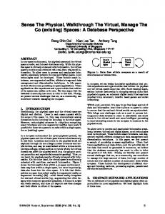
Figure 1. (a)–(d) The first three and the last 3D views in a computed view plan. The views may be at different height. (e)–(f) The final partial model created from the ten scans.
experienced operators will encounter considerable difficulty with topologically and geometrically complex shapes. Online visualization feedback may be helpful, but manual view planning is generally a slow and error-prone process. When multiple constraints and requirements have to be considered, it can become overwhelming or impossible for the human operators to produce a reasonably good view plan. The goal of this work is to automate view planning for the range acquisition of real-world indoor environments to reconstruct models without a priori knowledge of the scene geometry. Most common indoor environments, such as offices and residential dwellings, are challenging for automated view planning. They occupy a large volume of space, and
can be cluttered with many objects, which results in high visibility and geometric complexities.
1.1. The Next-Best-View Problem For 3D reconstruction, a priori knowledge of the scene geometry is not available to the automatic view planner. The first scan is made from a view selected by a human operator, and for each subsequent scan, the planner must determine its best view based on the information collected from the previous scans. This is often called the next-best-view (NBV) problem. The NBV problem is inherently a local optimization problem since global geometric information is unknown. It is NP-hard, and since it can be reduced to the set-covering problem, it is often solved approximately using a greedy approximation algorithm. A greedy NBV algorithm selects the view that maximizes a view metric as the best view for the next scan. The major challenge to a practical NBV solution is an efficient method to evaluate the view metric for a large set of views, using information provided by a partial model of the scene. Each evaluation can be computationally very expensive, since a large amount of information of the partial model may be involved, and visibility computations and other constraint evaluations are expensive. This apparent computation difficulty has limited many previous NBV algorithms to simple and small objects, incomplete search space, incomplete set of acquisition constraints and reconstruction quality requirements, and low-quality acquisition. Some early algorithms even ignore selfocclusion of the objects. However, an efficient algorithm to evaluate the view metric is actually possible. This is achieved by using a hierarchical approach to adaptively exploit the various spatial coherences inherent in the acquisition constraints and quality requirements.
1.2. Reconstruction Quality Requirements The goal of 3D reconstruction is to produce a 3D model of the real-world object or environment that satisfies some reconstruction quality requirements. Generally, we would like the range acquisition to achieve the following two quality requirements on the 3D model. (1) Completeness. The more surface area of the object that is acquired, the more complete the reconstructed model can be. When planning views for a limited number of scans, it is natural to want to maximize the amount of surface area that can be measured.
(2) Surface sampling quality. The surfaces of the object must be measured to meet a sampling quality requirement, which ensures that small surface features can be successfully reproduced in the reconstructed model up to the required resolution. View planning must maximize the surface area that reaches the required sampling quality. We have chosen to use surface sampling density as a measure of the surface quality. These two requirements are in contention with each other. For example, trying to maximize the amount of surface area that reaches the required sampling quality may reduce the amount of new surface area that can be acquired. Trade-offs must be made between them.
1.3. Acquisition Constraints There are several acquisition constraints that must be observed when planning a view of the scanner. Each constraint can be classified as one of the following types. (1) Positioning constraints. The scanner’s physical position is constrained by the physical construction of the scanner and the positioning device. A rotating scanner usually needs some space around it to operate and thus the viewpoint must be kept at least a minimum clearance distance away from any object in the environment. Other examples are that the scanner may be placed only between a minimum and a maximum height above the floor, but must never be placed above any object. A view that satisfies the positioning constraints is a feasible view. (2) Sensing constraints. These constraints determine whether a surface point in the scene can be measured from a view. For example, a surface point cannot be measured by the scanner if it is not visible from the range sensor, it is outside the field of view (FOV) or the depth of field of the scanner, or it is at a grazing angle with the light beam from the range sensor. (3) Registration constraint. When the scanner is moved to a planned pose, it is assumed that there will be positioning error. Therefore, the new scan has to be aligned or registered to the previous scans so that its information can be merged properly with the old one, and the scanner can be re-localized. However, this registration is not guaranteed to be successful. Factors that affect the registration accuracy between two surfaces are (1) the amount of overlap between them, (2) the shape constraint on the 3D rigid-body transformation between the two surfaces, and (3) the range measurement errors. The view planning algorithm must ensure that the new scan to be acquired
from the planned view can be successfully registered with the previous ones.
1.4. Contributions We have formulated a general view metric that is able to include many real-world acquisition constraints and reconstruction quality requirements. Our implementation has included both quality requirements listed in Section 1.2 and all the example acquisition constraints listed in Section 1.3. The major contribution of this work is the recognition of the various spatial coherences in the acquisition constraints and reconstruction quality requirements in the view metric, and the novel application of a hierarchical approach to exploit them. This greatly accelerates the evaluation of the view metric for a large set of views. We also propose a novel extension to the hierarchical view evaluation algorithm to take into account each view’s sensitivity to the potential scanner positioning errors. We have also derived a metric to predetermine whether a new view can satisfy the registration constraint. This metric considers all the three factors listed in Section 1.3. Our results show that the hierarchical approach can speed up view evaluation by one to two orders of magnitude over the straightforward method used in the previous NBV algorithms. These significant speedups have allowed our NBV algorithm to become, to the best of our knowledge, the first to be able to exhaustively evaluate a large set of 3D views with respect to a large set of surfaces, and to include many practical acquisition constraints and quality requirements, especially the sampling quality requirement, and the registration constraint that considers surface shape complexity and range measurement errors.
1.5. Paper Organization The paper is organized as follows. Section 2 reviews some of the previous work on view planning. Section 3 presents an overview of our solution, and explains some of the components of the solution. One of the components, the hierarchical view evaluation method, is explained in Section 4, and another component, the metric to predetermine registration accuracy, is briefly presented in Section 5. Section 6 presents some of our experiment results. Section 7 concludes the paper and discusses some potential extensions of this work.
2. Previous Work Most of previous work on view planning have been for small objects. The sensor position is often assumed to lie on a sphere surrounding the object, and always pointed at the center of the sphere, which may correspond to the center of the object or the feature of interest. The sphere is discretized to produce a fixed set of 2D viewpoints, and each viewpoint is independently evaluated with the partial model of the object [2, 7, 15]. Pito [9] proposed a 4D positional space to record discrete light rays that can reach points on the partial model. When a viewpoint is evaluated, each ray from the viewpoint is used to address the 4D positional space. Reed et al. [10] uses a different approach in which an occlusion surface on the partial model is selected by the user, and a single view volume is “projected” from the surface. The next sensor view is in the intersection of the projected view volume and the configuration space of the sensor. A similar approach is used by Sequeira et al. [13] to reconstruct indoor environments, in which multiple 3D view volumes are created for multiple occlusion surfaces. The next sensor view is selected from the intersections of these 3D view volumes. This method quickly becomes very complex and inefficient when the occlusion surfaces and the occluders are not simple. For reconstruction of indoor environments, it is usually impractical to exhaustively evaluate all views. González-Baños et al. [3] and Nüchter et al. [8] have chosen to use randomized methods to generate 2D views on a plane. Sanchiz and Fisher [11] use a combination of hill-climbing and exhaustive search optimization methods to search for a local optimal viewpoint. The viewpoint space considered is 5D—3D position, pan and tilt. Each test viewpoint is evaluated by a specially designed objective function, and lowresolution ray-casting is used to estimate visibility from the test viewpoint. Only a few existing view planning algorithms consider the registration constraint when computing the next view [11, 12]. However, the only criterion they consider is the amount of overlap between surfaces. All the methods reviewed above work only for monostatic range sensors, which are sensors whose light emitter and detector are co-located. On the other hand, the emitter and detector of a bistatic sensor are at different locations (e.g. triangulation-based range sensor). Our proposed hierarchical view evaluation algorithm was inspired by the hierarchical radiosity
new view position scanner
make scan
register scan
merge scan
compute new view
terminate Figure 2. The model acquisition cycle with automated NBV planning.
algorithm [4], which can be generalized to evaluate pair-wise interactions between extended objects. The hierarchical approach was later applied by Stuerzlinger to a model-based view planning problem to compute a set of 3D camera positions to maximize the amount of surface area of a synthetic scene model that can be imaged by the cameras [14]. The problem is highly simplified in that only the visibility constraint is considered and each camera is assumed to have a full spherical field of view. The main difference of this work from Stuerzlinger’s is the generalization of the hierarchical approach to include many considerations, constraints and requirements to enable practical view planning for real-world range acquisition. It has also been extended to take into consideration the effects of the scanner’s pose errors on the views’ scores.
3. Solution In the following descriptions of our solution, it is assumed that the range sensor is monostatic, and all the samples in a range image are measured from a single center of projection or viewpoint. These two assumptions are true for many commercial mid-range and long-range laser scanners that use time-of-flight range sensing. In the last section, we briefly describe how our method can be extended to bistatic range sensors. Figure 2 shows the model acquisition cycle with automated NBV planning. During a typical acquisition session, the model acquisition cycle is repeated multiple times. Besides evaluating views, a complete NBV planning system must be able to register and merge a new scan to the partial model. Only then can the partial model be used for view evaluation, in which the view that maximizes the view metric is chosen for the next scan.
3.1. Partial Model In this section, we first describe how to create a partial model from a single scan, and then describe how partial models can be merged. After a scan is made, the view planning system can be sure that the volume of space between the scanner’s viewpoint and the acquired surfaces (called true
(a) (b) (c) (d) Figure 3. Different types of surfaces in a partial model. (a) True surfaces. (b) Occlusion surfaces (red). (c) Hole-boundary surfaces (blue). (d) Image-boundary surfaces (green).
surfaces) is empty. However, volumes behind occluders, volumes in front of missing range samples (drop-outs), and volumes outside the FOV of the scanner are of unknown status. In the partial model of the single scan, these unknown volumes are separated from the known empty space by adding three types of false surfaces: (1) occlusion surfaces, (2) holeboundary surfaces, and (3) image-boundary surfaces. They are shown in Figure 3. Occlusion surfaces are added to connect surfaces across depth boundaries caused by occlusions. A way to detect these depth boundaries is by thresholding the distances between adjacent samples in the range image. Missing range samples result in holes in the true surfaces. The boundaries of these holes are connected to the scanner’s viewpoint using hole-boundary surfaces. Image-boundary surfaces are added to connect the range image boundaries to the scanner’s viewpoint. With the true surfaces and the added false surfaces, the known empty space is bounded. The false surfaces provide clues to how the unknown volumes can be resolved by subsequent scans. One strategy is to place the next view in the empty space where it can see as much area of the false surfaces as possible. This allows the next scan to “penetrate” as many of the false surfaces as possible, in the hope of resolving the unknown volumes behind them. This strategy is used in our view metric. One partial model can be merged to another of the same environment by performing the union of their known empty volumes and the union of their true surfaces. In our implementation, the partial model is represented using an octree. All surface types and empty space are represented. Every surface voxel contains a surface normal vector, and each true surface voxel also contains the minimum sampling density over the surface region that intersects it. Figure 4(a) shows an octree partial model constructed from a single scan of a synthetic room model. The scanner has 360° horizontal FOV but limited vertical FOV (60° below and 60° above the horizon).
otherwise f (v ) is 0; • r (v ) is 1 if the registration constraint is satisfied at view v, otherwise r (v ) is 0;
(a)
(c)
(b)
(d)
Figure 4. (a) An octree partial model. The gray voxels are true surfaces, red are occlusion surfaces, blue are hole-boundary surfaces and green are image-boundary surfaces. The white arrow points at the scanner’s viewpoint. (b) The feasible view volumes (in light-blue). (c) A true surface patch. (d) A set of occlusion surface patches.
When a new range image is acquired, it is made into a triangle mesh. A variant of the iterative-closestpoint (ICP) algorithm [1] is then used to align the mesh to the true surface voxels’ centers in the cumulative octree partial model of the scene. Next, the mesh is scan-converted to an octree partial model before it is merged into the cumulative partial model. Attributes in the resulting surface voxels are updated accordingly. To cope with registration errors and range measurement errors, if a true surface voxel in the cumulative partial model does not coincide with a true surface voxel in the other partial model, a search is performed over a very small neighborhood to find the nearest compatible true surface voxel in the other partial model. Compatibility is determined by the similarity of their surface orientations.
3.2. View Metric Our view metric is shown in Eq. (1), where h(v ) is the score of view v.
h(v ) = f (v ) ⋅ r (v ) ⋅
∫ c(v , p ) ⋅ w( p ) ⋅ t (v , p ) dp
(1)
p ∈S
where • S is the set of all surface points in the current partial scene model; it includes all true and false surfaces; • f (v ) is 1 if view v is a feasible view, i.e. all the positioning constraints are satisfied at view v,
• c(v , p ) is 1 if all the sensing constraints between view v and surface point p are satisfied, otherwise c(v , p ) is 0;
• w( p ) is the weight or importance value assigned to the surface type of p; the four different surface types are the true surfaces, the occlusion surfaces, the hole-boundary surfaces, and the imageboundary surfaces; • t (v , p ) is the improvement to the recorded sampling density at p if a scan is made from view v. We use the following definition for t (v , p ) .
t (v , p ) = max (0 , min (s (v , p ), D ) − q ( p ))
(2)
where • s (v , p ) is the sampling density at p if it is scanned from view v; this is referred to as the new scan sampling density; • D is the sampling density requirement for all surfaces; • q ( p ) is the maximum sampling density at which p has been scanned previously; this is referred to as the recorded sampling density; if p is on a false surface, then q ( p ) is 0; t (v , p ) is 0 if s (v , p ) ≤ q ( p ) or if q ( p ) ≥ D . In Eq. (1), the improvement in sampling density is summed up over all surface points in the partial scene model, including surface area of false surfaces. The view score h(v ) is the total gain in the number of surface samples at view v, given that the acquisition constraints are satisfied. In the metric, the false surfaces are treated just like the true surfaces, except that their recorded sampling density is 0. The weight w( p ) is used to trade-off between the completeness and the surface sampling quality requirements. To favor completeness, one can assign a large weight value to the occlusion surfaces and a small value to the true surfaces, and vice versa. We use w( p ) = 1 for all surface types in all our experiments.
3.3. Algorithm Overview Our strategy to evaluate h(v ) for all the views is to evaluate Eq. (1) in pieces, from least to most expensive to compute. Figure 5 shows the major steps in the evaluation of h(v ) .
new view
partial scene model
(F) check registration constraint
(A) compute feasible views
(B) extract planar patches
(E) rank views
(D) evaluate views
(C) rank patches
terminate Figure 5. The major steps in the NBV algorithm.
We first evaluate f (v ) for all views to eliminate the infeasible views. Next, we use our hierarchical view evaluation method to evaluate the integral part of Eq. (1) for all the feasible views. If all views have scores below a specified threshold, the view planner will suggest termination of the acquisition process. The feasible views are then ranked by their current scores. Starting from the highest-score view, the registration constraint function, r (v ) , is evaluated. A view is evaluated for r (v ) only if it is at least a specified distance away from all the previously-checked views. This is because views with similar scores tend to cluster near each other and they usually have similar registration accuracies. The first view found to satisfy the constraint is output as the next best view. The registration constraint is evaluated last because it is the most expensive to compute. To support the hierarchical view evaluation, surface voxels in the partial scene model are grouped into planar patches. Only false surface voxels and true surface voxels whose recorded sampling densities are less than the sampling density requirement D are grouped into patches. If all the surfaces have already reached the sampling density requirement, or all the patches are less than a specified size, the scene is considered satisfactorily acquired and the acquisition process can be terminated. The planar patches are then ranked in descending order of importance. The reason for ranking the patches is that sometimes only a limited amount of time is allotted for the view planning computation, and only the most important patches will be used to evaluate the views. Computing feasible views. The positioning constraints determine the feasible 3D locations of the views. In the implementation, an octree is used to represent the feasible view volumes. Initially, this feasible view octree is a cube that encloses all the empty space in the cumulative partial model. The cube is then “carved” until it becomes the feasible view
volumes. For example, to keep the scanner’s viewpoint a minimum clearance distance from all objects in the scene, all the non-empty-space cells in the partial scene model are enlarged by the minimum clearance distance on all sides. The feasible view octree cells are then recursively subdivided until each cell has reached a minimum viewcell size or it does not intersect any of the modified non-empty-space cells. Other positioning constraints listed in Section 1.3 are also implemented. Figure 4(b) shows the feasible view volumes computed for the partial model in Figure 4(a). Extracting planar patches. Surface voxels that have not reached the required sampling density are grouped into planar patches. Voxels of different surface types will not be grouped in the same patch. Each patch has the following attributes: (1) a bounding rectangle, (2) an approximate surface area, (3) the average recorded sampling density, and (4) the sampling deficit. The sampling deficit is defined as the number of samples needed to make the average recorded sampling density equal to the sampling density requirement D, i.e. sampling deficit = (D − average recorded sampling density) × approximate surface area. Figure 4(c) and (d) show some example patches. Ranking patches. The most important patch should have the greatest potential impact on the value of the view metric in Eq. (1). This leads to the following: the patch importance value of P = w(P ) × sampling deficit of P, where P is the patch, and w(P ) is the weight assigned to the surface type of P, which is the same as the weight w( p ) in Eq. (1). The patches are then sorted in descending order on their patch importance values.
4. Hierarchical View Evaluation Let g (v ) be the integral part in Eq. (1), i.e.
g (v ) =
∫ c(v , p ) ⋅ w( p ) ⋅ t (v , p ) dp
(3)
p ∈S
The next step of the NBV algorithm is to evaluate g (v ) for all the feasible views. Due to the potentially large area of surfaces in the partial scene model, a brute-force approach would be impractical. However, the amount of computation can actually be reduced by exploiting the spatial coherences in the sensing constraints and the sampling quality function in Eq. (3). The basic idea is that if a constraint is satisfied between a view v and a surface point p on the partial model, very likely the same constraint is also satisfied between another view v′ and p, provided v′ is near to v.
The same constraint is also very likely to be satisfied between v and another surface point p′ that is near p. We exploit these spatial coherences using a hierarchical approach. Neighboring views are first grouped into view volumes, and neighboring surface points are grouped into surface patches. The constraint is evaluated between each view volume V and a patch P. If it is entirely satisfied or entirely not satisfied between V and P, then the constraint evaluation is considered completed between every view in V and every surface point in P. If the constraint is partially satisfied between V and P, then we subdivide either V or P, and continue the evaluation on the children.
where s min (V , P ) and s max (V , P ) are the minimum and maximum s (v , p ) between V and P, respectively. We have chosen to let s (V , P ) = s min (V , P ) , and compute g (V , P ) using Eq. (6). If any sensing constraint is found entirely not satisfied between V and P, then s (V , P ) need not be computed and g (V , P ) = 0 . If c(v , p ) is not constant or s (v , p ) is not approximately constant between V and P, then we cannot compute g (V , P ) using Eq. (6). We can subdivide either V or P, and apply Eq. (6) on the subvolumes or the sub-patches. If patch P is subdivided, then
(
Suppose all the false surfaces and under-sampled true surfaces in the partial model have been partitioned into N patches {Pi | i = 1,K , N }, then Eq. (3) can be rewritten as N
g (v ) = ∑ g (v , Pi )
(4)
i =1
where
g (v , P ) =
)
(
g (V , P ) = g V , P + L + g V , P
4.1. Formulation
∫ c(v , p ) ⋅ w( p ) ⋅ t (v , p ) dp
(5)
p ∈P
(6)
where
t (V , P ) = max (0 , min (s (V , P ), D ) − q (P ))
(7)
and c (V , P ) , w(P ) and s (V , P ) are similarly defined as c(v , p ) , w( p ) and s (v , p ) ; a(P ) is the patch area of P, and q(P ) is the average recorded sampling density of P. In actual fact, the value of s (v , p ) does not stay constant between V and P. However, if every s (v , p ) between V and P is bounded within a small interval, then we consider it approximately constant. The value of s (v , p ) between V and P is considered approximately constant if
s max (V , P ) − s min (V , P ) ≤ εs s max (V , P )
k
)
(9)
where P1 ,K , P k are the sub-patches of patch P. If view volume V is subdivided, then g (V , P ) is replaced
(
)
(
)
with g V 1 , P ,K , g V m , P , where V 1 ,K ,V m are the
(
)
sub-volumes of V. In this case, g (v , P ) = g V i , P if
v ∈ V . The subdivision stops when c(v , p ) is constant and s (v , p ) is approximately constant between the view volume and the patch. i
4.2. Implementation
Now, we will focus on evaluating views with respect to a patch P, instead of with all the surface area in the partial model. Suppose the values of c(v , p ) and t (v , p ) remain constant between a view volume V and a patch P, where v ∈ V and p ∈ P , then g (v , P ) can be computed as
g (v , P ) = g (V , P ) = c(V , P ) ⋅ w(P ) ⋅ t (V , P ) ⋅ a(P )
1
(8)
In our experiment, the scanner has 360° horizontal FOV but limited vertical FOV. Since we assume that the scanner is always in the upright orientation, each view of the scanner is effectively only a 3D position. We use the feasible view octree to represent the view volumes. From the highest-ranked patch to the lowest, each patch is first evaluated with the top viewcell in the feasible view octree. A viewcell is subdivided into eight equal sub-viewcells, whereas a patch is subdivided into four sub-patches by splitting its bounding rectangle into four equal parts. A viewcell is not subdivided if it has reached the minimum viewcell size. Similarly, a patch is not subdivided if it has reached the minimum patch size. When either a viewcell or a patch is to be subdivided, we subdivide the patch if its longer side is larger than the viewcell’s width, otherwise the viewcell is chosen. We have implemented all the four sensing constraints listed as examples in Section 1.3. Each constraint is tested between a viewcell and a patch, and the result can be “entirely satisfied”, “entirely not satisfied”, or “partially satisfied”. We have also implemented an efficient way to compute the minimum and maximum new scan sampling density between a viewcell and a patch. Our efficient algorithms to
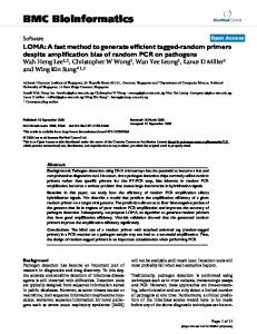
evaluate the sensing constraints and the sampling density are detailed in [6]. After all patches have been evaluated (or the allotted view evaluation time is up), a viewcell’s score is not yet propagated down to its children. Since each child viewcell contains part of the view volume of its parent viewcell, the scores in the children should include the parent’s score. Therefore, the score of each viewcell should be updated by adding to it the scores of its ancestors. The center point of each leaf node of the feasible view octree is a candidate view, to be ranked and tested for the registration constraint. The first candidate view that satisfies the registration constraint is chosen as the best view for the next scan. Many optimizations can be added to the basic hierarchical algorithm. If a sensing constraint ci is already entirely satisfied between V and P, but V or P is to be subdivided because some other sensing constraint is only partially satisfied, then ci need not be re-evaluated for the children of V or P. Another optimization is to order the evaluations of the constraints and the sampling density so that the most efficient one is first and the least efficient last. This is to exploit the many early exits in the algorithm, so that the more inefficient evaluations are less likely to be executed. Generally, the visibility constraint should be placed at the end. Figure 6(a) shows the feasible view volumes computed for a partial model of a large living room. These feasible view volumes are then evaluated with a patch shown in magenta color in Figure 6(b). The resulting best 500 viewcells are shown. The minimum viewcell size used is 4×4×4 inch3, and the minimum patch size is 2×2 inch2. A brute-force method took 259.6 seconds to evaluate the feasible views with the patch, while our hierarchical algorithm took just 11.9 seconds—a difference of more than 20 times. Typical speedups are between 10 to 100 times. Generally, larger and simpler scenes, and smaller minimum viewcell and minimum patch sizes result in larger relative speedups.
4.3. View Sensitivity to Pose Errors When the scanner is being positioned at a planned view, there may be pose error. Some views are very sensitive to pose errors, in that the view scores in the neighborhood of such a view varies greatly. The problem with using a sensitive view as the planned view is that many surfaces expected to be acquired at the planned pose may not be acquired at the actual pose. Pose error sensitivity can be easily incorporated into the hierarchical view evaluation algorithm. When evaluating a constraint or the new scan sampling density between a viewcell and a patch, the viewcell is first enlarged by the expected or maximum pose error in each of its dimensions. The effect of this is a lower viewcell score that accounts for only the surface areas that can be acquired by every view within the pose error bound of the views in the original viewcell. A surface area that can be acquired by some but not all views in the enlarged viewcell will not be included in the score. To our knowledge, this is the first NBV algorithm that directly incorporates pose error sensitivity in the computation of new views.
5. Registration Constraint The NBV algorithm must ensure that the new scan to be acquired from the planned view can be accurately registered with the previous ones. We have derived a metric, which considers all the three factors listed in Section 1.3, to estimate whether a view satisfies the registration constraint. These factors are (1) the amount of overlap between the new scan and the previous scans, (2) the shape constraint on the 3D rigid-body transformation between the them, and (3) the range measurement errors. The metric and the details of the derivation can be found in [5]. Figure 7 shows an example to demonstrate the room 2 room 1
(a)
(b)
Figure 6. (a) The feasible view volumes to be evaluated. (b) The results of evaluating the patch (magenta) with the feasible view volumes. The best 500 viewcells are shown.
(a)
(b)
(c)
highestscore view
final planned view
Figure 7. (a) A synthetic scene. (b) The scan made from the first room. (c) The highest-score view and the final planned view.
effectiveness of our registration constraint metric. The indoor scene has two rooms linked by a doorway. A scan is first made from the first room. To compute the view for the next scan, the candidate views produced by the hierarchical view evaluation are tested for the registration constraint. The highest-score view fails the constraint, and 21 other views are tested until one near the doorway is found to satisfy the constraint. A view is evaluated for the registration constraint only if it is at least a specified distance away from all the previously-checked views. We use a distance of two feet in the example. In fact, the scan acquired from the highest-score view does not have enough shape constraint in the overlapping region with the first scan, and registering them using our ICP algorithm actually fails. The final planned view does not have this problem.
7. Conclusion and Future Work
6. Results We have tested our NBV planning system in simulations and on real scenes. The scanners used in both cases have only 3D translational poses, and have full horizontal FOVs but limited vertical FOVs. We typically use a width of 2 inches for the surface voxels in the partial models. The minimum viewcell size used is 4×4×4 inch3, and the minimum patch size is 2×2 inch2. We also limit the amount of time that the system can spend on view evaluation in each cycle to 2 minutes. All the timings and results were obtained on a laptop computer with an Intel Pentium 4-M 1.6GHz CPU, and 768 MB of DDR RAM. Figure 1 shows the simulation results of acquiring scans of a synthetic kitchen model. The main kitchen area has three smaller pantry-sized rooms connected to it. The acquisition was manually terminated after the tenth scans. Figure 1(a)–(d) show the evolution of the partial model after each new scan is merged. The final view plan is shown in Figure 1(d). Every cycle, the hierarchical view evaluation was able to evaluate all the patches with all the feasible views within the allotted two minutes. Other steps of the system, for
(a)
(b)
2
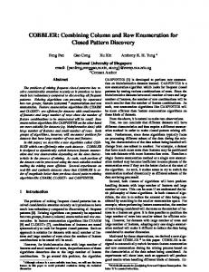
example, range image processing, registration of scan, octree partial model creation and merging, extraction of patches, evaluation of the positioning and registration constraints, took an average of 35 seconds altogether. Figure 8 shows the acquisition of a real building interior using a DeltaSphere-3000 laser scanner. The acquisition process was manually terminated after the fifth scan. Figure 8(a) shows the view plan. The elongated occlusion surfaces in the final partial model are the results of the scanner “seeing” into other rooms through the small glass windows on the doors. Every cycle, more than 75% of the patch areas can be evaluated with all the feasible views. This experiment demonstrates that our NBV planning system is robust for real-world applications.
1
4
5
We have demonstrated that, using our hierarchical view evaluation method, exhaustive 3D view evaluation for greedy NBV planning is actually practical. Moreover, our view metric includes many real-world acquisition constraints and quality requirements (all listed in Section 1.3). We believe the view metric and the hierarchical evaluation method are general enough to allow many other useful constraints and requirements to be added. Another advantage of the hierarchical method is that view sensitivity to pose errors can be easily incorporated. Our registration constraint metric is able to take into account the amount of overlap region, the shape complexity and the range measurement errors. The hierarchical view evaluation method can be extended to scanners with higher-dimensional pose. The most general pose in practice is 5D—3D position, pan and tilt. The major challenge is the potentially large amount of memory required to represent the 5D views. The key to a feasible solution may be a clever method to better exploit the coherences in the views so that they may be more compactly represented. The hierarchical method may also be applied to scanners with bistatic sensors. The basic idea is that for each view volume of the scanner, each of the two sensor viewpoints forms a 3D swept volume. A subdivision of the scanner’s view volume will also subdivide the 3D swept volumes. However, since the swept volumes may be of more complex shapes, it is not known whether the spatial coherences can still be efficiently exploited.
3 Figure 8. (a) The view plan computed for a real scene. (b) The final partial model and the feasible view volume.
References [1] P. J. Besl and N. D. McKay. A Method for Registration of 3-D Shapes. IEEE Transactions on Pattern Analysis
[2] [3]
[4]
[5]
[6]
[7]
[8]
and Machine Intelligence (PAMI), 14(2), pp. 239–256, 1992. C. I. Connolly. The Determination of Next Best Views. Proceedings of IEEE International Conference on Robotics and Automation, pp. 432–435, 1985. H. González-Baños, E. Mao, J.-C. Latombe, T. M. Murali and A. Efrat. Planning Robot Motion Strategies for Efficient Model Construction. Proceedings of International Symposium on Robotics Research, pp. 345–352, 1999. Pat Hanrahan, David Salzman, Larry Aupperle. A Rapid Hierarchical Radiosity Algorithm. ACM SIGGRAPH Computer Graphics (Proceedings of SIGGRAPH '91), 25(4):197–206, July 1991. Kok-Lim Low. Some Conditions for Accurate Surface Registration. Technical Report TR05-008, Department of Computer Science, University of North Carolina at Chapel Hill, 2005. Kok-Lim Low and Anselmo Lastra. Efficient Constraint Evaluation Algorithms for Hierarchical Next-Best-View Planning. Proceedings of the Third International Symposium on 3D Data Processing, Visualization and Transmission (3DPVT), June 2006. N. A. Massios and R. B. Fisher. A Best Next View Selection Algorithm Incorporating a Quality Criterion. Proceedings of British Machine Vision Conference, 1998. A. Nüchter, H. Surmann, and J. Hertzberg. Planning Robot Motion for 3D Digitalization of Indoor Environments. Proceedings of IEEE International Conference on Advanced Robotics, 2003.
[9] R. Pito. A Sensor Based Solution to the Next Best View Problem. Proceedings of IEEE International Conference on Pattern Recognition, pp. 941–945, 1996. [10] M. K. Reed, P. K. Allen, and I. Stamos. 3-D Modeling from Range Imagery: An Incremental Method with a Planning Component. Proceedings of IEEE International Conference on Recent Advances in 3-D Digital Imaging and Modeling (3DIM), pp. 76–84, 1997. [11] J. M. Sanchiz and R. B. Fisher. A Next-Best-View Algorithm for 3D Scene Recovery with 5 Degrees of Freedom. Proceedings of British Machine Vision Conference, 1999. [12] W. R. Scott, G. Roth, and J.-F. Rivest. View Planning with a Registration Component. Proceedings of IEEE International Conference on 3D Digital Imaging and Modeling (3DIM), 2001. [13] V. Sequeira, J. G. M. Gonçalves, and M. I. Ribeiro. Active View Selection for Efficient 3D Scene Reconstruction. Proceedings of International Conference on Pattern Recognition, Track1: Computer Vision, pp. 815–819, 1996. [14] Wolfgang Stuerzlinger. Imaging All Visible Surfaces. Proceedings of the 1999 Conference on Graphics Interface, pp. 115–122, June 1999. [15] G. H. Tarbox and S. N. Gottschlich. Planning for Complete Sensor Coverage in Inspection. Computer Vision and Image Understanding, 61(1):84–111, January 1995.