phone system consists of three parts: a Mobile Station Center (MSC) server, ... client initiates a call, it sends a request to the MSC server firstly, and then the client ..... Scenario 01: Add 911 calls, and it has higher priority to other phone calls.
Adaptive Scenario-Based Object-Oriented Test frameworks for Testing Embedded Systems W. T. Tsai*, Yinghui Na*, Ray Paul+, Fan Lu* *Department of Computer Science and Engineering Arizona State University Tempe, AZ 85287 +
Investment and Acquisition Department of Defense Washington, DC
Abstract This paper presents a process to develop adaptive object-oriented scenario-based test frameworks for testing embedded systems. Embedded systems often require rigorous testing due to the mission-critical nature of their applications, and they are often developed as a family of products. The process uses techniques such as design-forchange, design patterns, scenarios, ripple effect analysis, and regression testing. This paper then uses an example to illustrate this process by applying to it to test a mobile phone system, and the framework constructed can facilitate generation of numerous test cases quickly with minimum effort, and it can also accommodates many changes suggested by another party without changing the overall structure of the framework. Keywords: Object-oriented test frameworks, scenarios, test scenarios, design patterns, test reusability, regression testing, and embedded systems, 1.
Introduction
Embedded systems often under a rigorous multistage of testing and validation including requirement validation, design review, code inspection, unit testing, integration testing, system testing, and field evaluation. Furthermore products are constantly evolving as technology and market needs change. In many cases, a family of products will be developed rather than single products, and products evolve by adding, modifying or deleting features from earlier versions. Thus, all the products within a family are similar to each other in terms of functionality as well as design [18][19][16]. This has been observed in both telecommunication [34] and safety-critical implantable medical devices [24]. This paper addresses testing a family of embedded systems. As the system and its software keep on changing, testing must keep on changing to test the modified system. New test cases must be developed to test new or modified features [11][32], and regression testing must be constantly applied [17] to ensure that the system remains consistent after modification.
1
To cope with changes, change scenarios or those parts that are subject to change are often encapsulated by data abstractions or classes [18], but in object-oriented (OO) programs, changes can be encapsulated in design patterns [8] and architecture, and frameworks [6]. An OO framework is essentially a partially implemented system, and it embodies a generic design ready for customization for a particular application. Numerous OO frameworks have been developed recently for a variety of applications, and these frameworks often use OO design patterns extensively. Scenarios and use cases have been widely used in system and software development to specify system requirements. However, scenarios can also be for testing [26][1]. For example, a scenario can specify subsystems involved as well as input and output data including their types and parameters. In our scenario model, a scenario describes a function from the end user’ point of view, and scenarios are grouped in scenario groups, and each scenario group represents a collection of functionally related scenarios or other scenario groups. A sub-scenario is a decomposition of a scenario, and it represents a subfunction provided by the software. This paper applies OO framework techniques to organize test scenarios and cases, and illustrates this idea to test an embedded system, a mobile phone system. In this approach, requirements of a System Under Test (SUT) is first specified using the scenario model, then complex test scenarios are generated. An OO framework is then developed to represent these scenarios. Those that are likely changed are encapsulated by design patterns in the framework. To illustrate this approach, this paper uses a mobile phone system1 as the SUT. A mobile phone system consists of three parts: a Mobile Station Center (MSC) server, several Base Station (BS) servers, and clients. An MSC server allocates a BS server to a client upon requesting from that client. The MSC Server keeps running in the session. When an MSC server receives a request from a client, it allocates one of the BSs to serve that client by sending the IP address and socket port number of that BS to the client. The BS server sends frames to the client every 50 millisecond when a client is connected to a BS server. Multiple BS servers can exist in a system. Each BS server has different port number. In addition, every BS server has limited channels. When the BS receives a request from a client, it allocates one of available channels to that client. If no channel is available, the call is dropped. Multiple clients can be active at any given time. When a client initiates a call, it sends a request to the MSC server firstly, and then the client receives the IP address and socket port number of a BS server. When it receives the frames sent from the BS server, it will write a message into a log file. After the framework is constructed, we asked a professional engineer to suggest change scenarios based on the original system requirements. She proposed ten changes, and all of them except one can be easily updated in the framework without changing the overall
1
The requirements of the mobile phone system is given by a person who has a PhD in CSE and has been working as a supervisor in a major telecommunication equipment company for more than 5 years.
2
design structure. The reason that one change that could not accommodated was that we had no access to the specific hardware specifications suggested. This paper is organized as follows: section 2 discusses the related work on test frameworks. Section 3 introduces the scenario-based test framework, and an example framework is constructed using JUnit [13]. Section 4 describes the process of handling change scenarios and regression testing in the test framework. Section 5 discusses the production rate with the mobile phone example. Section 6 concludes this paper. 2.
Related Work
Test frameworks have been presented in [7][15][24][13][9]. Specifically, Firesmith [7] and McGregor [15] proposed several testing strategies based on the class diagram of the application. For example, McGregor proposed to develop a parallel architecture (parallel to the design structure of SUT) to test the SUT, and place test methods as a part of the class. This approach is essentially a white-box approach of constructing test frameworks. In [24], a test framework is developed to test safety-critical embedded systems. The framework has been used at an industrial site and achieved about 70% reduction in effort and cost in producing test cases. It is interesting to observe that the SUT is not an OO application, but the test cases are organized in an OO manner. JUnit is a test framework that aims at white-box unit testing for Java programs, thus the name JUnit (J stands for Java, unit stands for unit testing). The JUnit uses five design patterns in its architecture. When developing their own test applications with JUnit, one needs to follow a predefined structure that consists of a Test interface, testCase abstract class, testSuite class, and a testResult class. Cactus project [4] develop a test framework built on top of JUnit to test server-side Java code, specifically servlets, and EJBs. Thus, it can also be viewed as an extension of JUnit, however, because server-side Java code must interact with client-side code, Cactus addresses integration testing. HttpUnit [9] is a test framework that automates website testing. It is written in Java, and it emulates the browser behavior such as cookies and authentication. HttpUnit is a blackbox test framework that aims at testing websites. The test framework approach proposed in this paper is different from these frameworks. It is platform independent and it starts from analyzing system requirements expressed as scenarios. Like the approach in [24], the SUT does not need to be an OO application to take advantages of cost and effort saving in generating test cases from the framework. Furthermore, this framework considers complex test scenarios. 3.
Scenario-Based Test Framework
3
This paper proposes a process to develop a test framework based on analyzing system scenarios and possible future changes, and encapsulate these potential changes by design patterns in an OO test framework. Essentially, the process follows the design-for-change initially proposed by Parnas [18]. While developing the SUT with the framework approach, one can develop the test framework by using the same scenarios. Specifically, this process is as follows: • • • •
Specify system requirements by analyzing operational scenarios; Identify those areas of the systems that are likely to be changed; Develop the SUT with scenarios; Develop the OO test framework with scenarios.
By using the test framework, one can generate numerous test cases quickly with minimum effort. Section 5 describes the test production rate. When the system is changed, a tester can then reuse many test scenarios embedded in the test framework to generate new test scenarios and cases, and to select test cases for regression testing. Section 4 describes how a test framework can handle changes in the systems and/or test, and how regression test cases can be selected. 3.1. Specifying Scenarios Scenarios are derived from system requirements, and they often represent the functional aspects from the end user’s point of view. These scenarios can be atomic scenarios or complex scenarios. An atomic scenario verifies system correctness with individual functions, while a complex scenario executes multiple functions in a session to detect those defects that are difficult to be detected by atomic scenarios, and it can be used for stress testing if numerous atomic scenarios are involved. Before generating scenarios, one needs to perform a risk analysis on the requirements to identify those risky scenarios or those scenarios that must be operational to be accepted by the customer. A scenario with the highest risk will be ranked one, and the one with lowest risk will be ranked ten. For example, the mobile phone system has the following high-risk scenarios: • •
MSC server is started successfully: risk rank 1 BS server is started successfully: risk rank 1
After analyzing the mobile phone system, 23 atomic scenarios are obtained. Figure 1 shows two such atomic scenarios. One may find others in appendix A.
4
Scenario1: 1 Description: start an MSCServer successfully with a valid port number Constraints: working environment is set correctly; Scenario 2: 3 Description: start an instance of the Client with valid IP and port number Constraints: the MSCServer must work well
Figure 1: Examples of Atomic Scenarios Scenarios can be grouped. Specifically, a scenario group is a collection of functional related scenarios or scenario groups. A sub-scenario is a decomposition of a scenario, representing a sub-function provided by the software. Figure 2 shows the scenario tree for the mobile phone system, in which the system is decomposed progressively into multiple levels of scenario groups, scenarios, and sub-scenarios. A complex scenario is a composition of atomic scenarios to model complex usages of the system. In a complex scenario, scenarios are connected using control constructs such as sequencing; which is to define sequenced executions; conditioned; which is to add decisions to complex scenarios, concurrent; which is to define the simultaneous executions, and iterative, which is to define the repeated executions. A pseudo code based expression is used to describe the complex scenario. Figure 3 shows the pseudocode representation of the complex scenario “100 clients are connected to an MSC server simultaneously”: • •
Scenario 1: “Start MSCServer successfully”; Scenario 2 “Start a client successfully”.
{Scenario 1; If ((the working environment is set up correctly)AND (MSC server is started)) then Scenario 2100;} Figure 3: A Complex Scenario Example
5
SG0. Mobile Phone System SG1. Start MSCServer s11. Start MSCServer successfully
SG. ... s. ...
Scenario group Scenario
ss. ...
Sub scenario
s12. Fail to start MSCServer SG2. Start BSServer s21. Start BSServer successfully s22. Fail to start BSServer
SG3. Client connection SG31. Start client s31. Start a client successfully ss311. Initialize ss312. Authentication ss313. Approve SG311. Fail to start a client s32. Fail to approve ...... SG32. Connect to a BSServer ...... ......
Figure 2: An example of the scenario model Scenarios may relate to each other with the following relationships: • • • •
Independent: two scenarios are independent with each other if one can happen regardless of the other. Trigger/trigger-by: the execution of a scenario triggers the other scenario to activate. Mutually exclusive: two scenarios are mutually exclusive if they cannot exist at the same time. Related: two scenarios are related to each other if they are used in the same scenario group or they are mutually exclusive.
Scenario relationships can be used to eliminate those infeasible and useless combinations of complex scenarios. Recall that a complex scenario is a combination of other scenarios including atomic scenarios. Thus, potentially, one can generate an infinite number of complex scenarios. Even one restricts generating a certain kind of complex scenarios, the number of possible scenarios can still be enormous. For example, if one wishes to generate a set of complex scenarios formed by two atomic scenarios, one can have 23x23 = 529 possible scenarios. Similarly, one can generate 23x23x23 = 22,167 complex scenarios formed by combination of three atomic scenarios. One can continue in the manner to generate complex scenarios formed by more atomic scenarios, and it is
6
apparent that the number of possible scenarios that can be generated is simply too large to be covered. However, after analyzing these complex scenarios, one can find many of them are infeasible and can be safely discarded, e.g., a complex scenario containing two scenarios that have “mutually exclusive” relationship with each other is infeasible. In fact, one needs to generate complex scenarios with sub-scenarios that are related to or independent with each other. In this way, one can eliminate many of these infeasible scenarios. For example, the complex scenario in figure 3 consists of 101 atomic scenarios with one Scenario 1 and 100 Scenario 2. Since Scenario 1 has a related relationship with Scenario 2, and Scenario 2 has an independent relationship with itself, this complex scenario is feasible. 3.2
Identify Change Scenarios
The design-for-change needs to identify potential changes and encapsulate them in the design at the beginning, and Parnas suggested that hardware dependent parts, input and output, data structures, algorithms are likely to be changed. For those parts that are likely to be changed, one may find a suitable design pattern to encapsulate them, so that when the system is changed, the impact to the rest of system is minimized. In the mobile phone system, some features are not likely to be changed. For example, it must have at least one MSC server and one BS server, and both servers must provide receive, send, and close functions. For an MSC server, it must provide a function to allocate a BS server to a client. In addition, a client must be capable of making connection with the MSC server and the BS server. These can be viewed as invariants or not likely to be changed in the mobile phone system. On the other hand, the following features likely to be changed: •
Scenario 3: Upon a request from a client, the MSC server should establish a socket communication with that client, allocate one of the BS servers to this client, and send to the client the IP address and port number of the BS server allocated.
This scenario is likely to be changed because the MSC may send additional information to the BS server in the future, information such as acknowledgement. •
Scenario 4: After the establishment of the connection, the client should be able to receive a frame from the BS server every 50 milliseconds.
This scenario is likely to be changed because in the future, the BS server may need to respond less than 50 milliseconds, say 20 milliseconds as technology improves. Both of these change scenarios can be identified using the checklist provided by Parnas because both are related to input and output. Other sample change scenarios are listed in Appendix B.
7
3.3
Develop The SUT with Scenarios
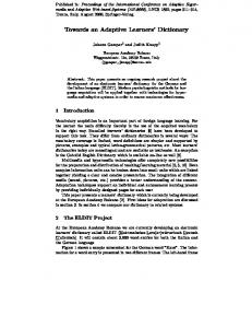
Once system scenarios including change scenarios are identified, one can develop the SUT from those scenarios. Figure 4 shows the OO design of the SUT. Since a scenario group represents one functional aspect of the SUT, one can make a scenario group as an abstract class or an interface, and then one can organize all scenarios of a scenario group into one or several subclasses of the abstract class depending on how complex the scenario group is. A scenario represents more fine-grained functional aspects than a scenario group, and thus one can implement a scenario as a class or a method in a class. A sub-scenario represents one operation of a functional aspect, so it is implemented as a method of a class. An OO framework is essentially an OO application but with change scenarios encapsulated in design patterns. Thus, one should identify classes and their methods with these change scenarios, and use appropriate design patterns to encapsulate them by design patterns. Analyzing scenario tree helps identify classes. Since a scenario group represents a set of function related scenarios, one can generate a class or several related classes from a scenario group. In addition, a scenario or a sub-scenario indicates a function provided by a class, and thus one may add methods to a class by analyzing scenarios or sub-scenarios. For example, the scenario group “ start an MSC server” organizes all scenarios related an MSC server, and thus one can generate an MSCServer class. Similarly, this scenario group has dependent scenarios and sub-scenarios, and one may generate related methods for class MSCServer. For example, the scenario “start up an MSC server with valid port number” is included in the scenario group “start an MSC server”, and then one may add a method startup in class MSCServer. From the change scenarios identified earlier, one may find suitable design patterns to encapsulate them. After analyzing the SUT, the design pattern Abstract Factory with intent “choose and return an instance of a class from a number of similar classes based on data you provide to the factory” [8] is useful here because both MSC server and BS server have similar functions: both can be started up, send, and receive messages. So that one class serverImpl with pattern Factory is used whenever a class cannot anticipate which kind of server it must create or a class uses its subclasses to specify which classes it creates. In addition, the SUT design uses the Bridge pattern. The design pattern Bridge emphasizes on separating the interface of class from its implementation, so that either can be varied separately. In this mobile phone example, one may separate the implementation of a server from its declaration, and thus one interface server that has method startup(), send(), and receive() declaration is added to the SUT. Once constructed, the framework can accommodate changes easily. For example, whenever a server changes the implementation of the method send() by adding new feature which is to send an acknowledge message, one needs only to change the
8
implementation of send method without changing any others, and this will not affect other parts. Figure 4 shows the design of the mobile phone system that consists of the MSCServer, BSServer, and Client. Note that developing the SUT with the framework approach is optional. Some commercial companies have used OO frameworks to implement embedded systems during development, but the framework features are removed in production to reduce code size and increase execution speed. The OO test framework can still be developed regardless whether the SUT is developed using the framework approach or not.
Server
Client send() receive() connect() di sconnect() function()
startU p() send() receive()
ClientIm pl ServerIm pl
M SCServer
allocateBSServer() serverW orkTask() Listen()
BSServer
Cl ientO ne
startTim er() disableTim er() run()
getB SIP() getB SPort() checkN um ber()
ClientTw o
clientTw o()
Figure 4: The Architecture of SUT 3.4
Develop The OO Test Framework with Scenarios
In addition to form the basis of the SUT design, scenarios can also be used to develop the test framework. Although both SUT and test framework are developed with scenarios, they are different: the SUT focuses on implementation of the functionality, while the test framework focuses on testing the same functionality. For example, scenario says, “start an MSCServer successfully with a valid port number” with the constraints that the working environment is established correctly. For the SUT development, one needs only to design methods to implement this scenario. Specifically, class MSCServer should have a method start to initialize an MSCServer.
9
On the other hand, to design a test framework for the same scenario, a tester needs to consider various situations to test this specific scenario. Specifically, it is necessary to examine the possible conditions that are related to this specific scenario, and what the appropriate reactions when this system is activated under these conditions are. For example, to test this scenario, a tester must check whether the environment has been properly set up, and method setUp() can be used. Then another method scearnio1Test() tests whether the MSCserver starts properly by checking whether the start() method of the MSCServer is called or not . If the startUp() method is called and the MSCServer is started successfully, this test is passed otherwise it fails. Finally, the test must clean up the state of SUT after test so that another test can be run without accidentally introduced a test dependency [17]. Furthermore, one needs to consider change scenarios related to this scenario. For example, the MSCserver startup may include more operations such as returning an acknowledgement to the client. In this case, only scenario1Test() needs to be changed, but the setUp() and cleanUp() methods do not need to be changed. After examining all these cases, one can recognize that all these related test scenarios can be encapsulated in Template Method design pattern as shown in Figure 6. This test scenario inherits from class UnitTesting because this test scenario involves only on class only, thus it is unit testing. The class UnitTesting defines methods that subclass Scenario1Test can customize for specific tests. The class Scenario1Test also encapsulates change scenarios by defining a template method MSCserverTest(), and this method uses setup(), senario1Test(), and cleanUp() as its primitive operations. In this way, when the requirement is changed, a tester can simply define a new subclass of Scenario1Test, and implement a new method Scenario1Test(). In this way, many of existing test routines and infrastructure can be reused. U nitT esting
setU p() scenarioT est() runTest() cleanU p()
S cenario1T esting changeS cenario M S C S erv erS tartupT est()
Figure 6: Test Scenario Encapsulation by Template Method Design Pattern
10
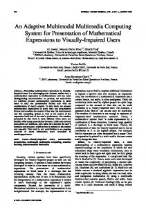
3.4.1. Implement a Test Framework Using JUnit JUnit [13] is a framework for repeatable unit tests for Java-based application and it consists of a testCase, testResult, testSuite, and test. In addition to provide the test operations, the test framework specifies scenarios in its implementation. The test framework proposed in this paper is different from JUnit in many ways. First, the test framework proposed cover both unit testing and integration testing, and it is developed using the concept of design-for-change and scenarios. However, it is possible to implement the proposed test framework by using and extending JUnit. Specifically, the class testCase, testResult, and testSuite can be reused, and new classes such as UnitTesting, and IntegrationTesting can be added as shown in figure 7. Furthermore, another class CompositeScenario is introduced, and it participates in design pattern Composite with IntegrationTesting to construct complex scenario testing. CompositeScenario is a subclass of IntegrationTesting, but it also contains an attribute of type IntegrationTesting. An example of developing a test for composite scenario “100 clients are connected to an MSC server simultaneously” shows the usage of the test framework. After analyzing the scenario, one may find that this scenario consists of 101 atomic scenarios that are 100 “connect a client to an MSC server” and 1 “start an MSC server”, so that one first needs to develop the test for atomic scenario by extending UnitTesting, and TestCase in JUnit, then one overwrites the corresponding methods: setUp(), runTest(), cleanUp(). After completing the unit testing, one may consider developing test for the composite scenario. The first step of developing test for a composite scenario is to add all child scenarios into the composite scenario by overwriting method addToChild(), and then one may run the test by calling method runTest() in each atomic scenario. Note that one needs only to write setUp() and cleanUp() once.
11
FunctionalTesting
T est
scenarioT est()
TestC ase
TestSuite
U nitT esting
IntegrationTesting
setU p() runTest() cleanU p()
setU p() runT est() cl e anU p()
TestR esult Com positeScenario JU nit
ad dT oC hild() rem oveFrom Child() ge tChild() scenarioTest()
Scenairo2T esting testStartAClient()
Scenario1Testing
BS StressTesting
M SCFocusT esting
testStartAnM S CServer()
Figure 7: The Architecture of Test framework 3.4.2. Develop Test Cases from the Test Framework The test framework provides a place where test scenarios can be generated, and once generated, test cases can be generated by examining the inputs and outputs of test scenarios based on various testing techniques such as partition testing, boundary value testing, random testing, and equivalent partition [12]. In most cases, each test scenario is associated with multiple data and each data has multiple attributes. To generate test data, one can apply different technique to different data and even to different attributes, and test cases are obtained from various combinations. For example, the test scenario “start an MSCServer with IP and port number” includes two associated data: IP address and port number. A correct IP address can be 144.169.25.7, and the correct port number is 222. When one generates test cases for this test scenario, one can use different technique like boundary value, random testing to select different test data.
12
4.
Regression Testing and Ripple Effect Analysis
Once the system is modified, it is necessary to update the system so that it will remain consistent, and it is also necessary to re-validate the system. Essentially, it is necessary to perform the following tasks: 1) Update the SUT; 2) Perform ripple effect analysis (REA) to ensure that the components of the modified SUT is consistent with each other; 3) Develop new test cases to test the modified feature; and 4) Perform regression testing to ensure that those parts that are supposed to remain unchanged are indeed unchanged after modification. Updating the SUT There are three types of changes: addition, deletion and modification. The addition/deletion/modification of a requirement item usually results in changing the corresponding operations on scenarios, which are then propagated to the other test artifacts including other scenarios and test cases. Fortunately, because the SUT is implemented as an OO framework, changes may be easily accommodated. For example, whenever a change happens in the implementation of the send() method in an MSC server class, one needs only to change the implementation of that method rather than affecting other parts. Ripple Effect Analysis on the SUT The REA process is an iterative process as shown in Figure 8. Our scenario model enables scenario dependency and traceability analysis, which can be used for scenario slicing and functional Ripple Effect Analysis (REA) [29]. The REA process [32] is an iterative process of scenario-based regression tests selection: (1) A change request is first mapped to a set of potentially affected scenarios; (2) By traceability analysis, one can trace a scenario to its associates and identify and validate the set of other affected other software artifacts; (3) Scenario identification and validation iterate until no more ripples exist. A key component of this process is dependency analysis. Dependency analysis for code has been thoroughly addressed by the programming language and compiler communities, however, dependency analysis for scenarios is still emerging [29], and it uses input, output, and conditions of scenarios to perform dependency analysis. Note that this process can be applied at any artifacts produced during the development, artifacts such as requirement documents, design specifications, code, and test. Fortunately, because this SUT is implemented as an OO framework, changes may have minimum impacts to the rest of system. For example, if a change happens in the implementation of the send() method in an MSC server class, one may find other affected scenarios that include scenarios have “related” relationship with it such as “connect a
13
client to an MSC server with valid port number” or “start an MSC server with valid port number”. Once one found the affected scenarios, one may determine whether it is actually affected or not. After analyzing, one may find the scenario “start an MSC server with valid port” is not affected by this change, while the scenario “connect a client to an MSC server with valid port number” is affected. Develop New Test Cases for the Modified Feature After the system has modified, including those that are affected by ripples are handled, it is necessary to test those modified features. For example, if the test cases for scenario “start an MSC server successfully” is changed by adding new feature into send() method in the MSCServer, one needs to develop new test cases for modified feature. In this example, new test cases are as follows:
Parameters Acknowledge type Server name
Data selected {“Successfully”, “failure”, “ “} {“149.169.25.7”,”149.169.25.6”,“149.169.25.8”,”149.159.22.3”, “000”“lll”,”xxxx”, “49.169.22.6”} Figure 8: New Test Cases for Change Scenarios
Regression Testing Regression testing has the following steps [17]: • • • • •
Test case selection Test case re-validation Test case execution Failure identification Fault identification and mitigation
However, regression testing using OO test framework differs from conventional regression testing only in test case selection. In most industrial test sites, test cases are listed in tables with cross references such as traceability to modules and requirement items. Test case selection in this kind of environment is to search all the test cases with appropriate cross references. However, test case selections in an OO test framework is different because test cases are attached to test scenarios embedded in the test framework rather than listed in a table. Furthermore, in conventional regression testing, one may always use the default test case selection strategy, i.e., select all. In fact, select all is safe and frequently used in computer industries [17]. However, it is no longer safe to select all the test cases in an OO test framework because many of them are specific to certain change scenarios, and if the current implementation does not use a specific change scenario, the related test cases cannot be used.
14
However, from a given implementation of the SUT, it is possible to identify all the scenarios that are applicable to it, and then its associated test scenarios can be traced and identified. Use all the test cases associated with those test scenarios as the default strategy. Furthermore, some common regression testing strategies can be used here in combination. For example, one may use select all high-risk scenarios, highly-used scenarios, randomly selected scenarios, or use a time-wise strategy for regression testing. Specifically, different set of test cases can be selected at different time interval with sufficient overlap to ensure system reliability and quality. For example, module test cases can be re-run daily, while all integration test cases are re-run weekly and at major milestones. 5.
Evaluation
This is to show that the scenario-based test framework developed can generate numerous test cases quickly. In addition, if there is a change, the framework can be updated quickly to generate new test cases to test new or modified features. Production Rate With the test framework, numerous test cases can be generated via examining the inputs and outputs of the scenario, based on various testing techniques such as partition testing, boundary value testing, random testing, and equivalent partition. In most cases, each scenario is associated with multiple data and each data has multiple attributes. To generate test data, one can apply different technique to different data and even to different attributes, and test cases are obtained from various combinations. The following test cases are generated once test scenarios are obtained from the framework as shown in Figure 9. Scenario Scenario 1 Scenario 2 Scenario 3 Scenario 4 Scenario 5 Scenario 6 Scenario 7 Scenario 8
Number of Test Cases 3,470 3,470 5,850 3,470 3,470 5,850 5,850 3,320
Scenario Scenario 9 Scenario 10 Scenario 11 Scenario 12 Scenario 13 Scenario 14 Scenario 15 Scenario 16
Number of Test Cases 7,820 5,478 6,525 7,435 8,920 10,020 3,920 2,030
Scenario Scenario 17 Scenario 18 Scenario 19 Scenario 20 Scenario 21 Scenario 22 Scenario 23
Figure 9: Test Cases for Scenarios Change Scenarios
15
Number of Test Cases 8,422 9,000 22,394 5,020 3,490 9,650 7,046
To demonstrate the framework can adapt to changes, we asked a professional engineer2 to examine the original mobile phone system requirements, and suggest changes. She suggested ten changes, and these changes covered both the software and hardware aspects. The test framework handles all except one. The test framework could not handle the only change because we had no access to specific hardware mentioned. Changes suggested by the engineer that can be handled are as follows: • • • • • • • • •
Scenario 01: Add 911 calls, and it has higher priority to other phone calls Scenario 02: Add an inter-state long distance call Scenario 03: Add an international distance call Scenario 04: Add a 1-800 call Scenario 05: Add user account management Scenario 06: Change user policy Scenario 07: Add display message from the weather forecasting center Scenario 08: Add a same type of BS Scenario 09: Add a different type of BS
The changes identified can be categorized as: input (Scenario 01-04), adding new feature (Scenario 05), business rule (Scenario 06), output (Scenario 07) and configuration (Scenario 08 and Scenario 09). The changes may affect the design, implementation and test cases. For example, Scenario 01 allows dialing three-digital telephone numbers. The corresponding method must be added in the system design and implementation. One also must generate the test scenario with input as three-digital number, and test cases. Change Scenarios Scenario 01: make 911 calls
Scenario 02: add interstate long distance call
Scenario 03: add an
Change Procedure This can be easily incorporated by adding a new method to class MSCServer. The priority can be easily updated by adding a condition statement in startup() method. This is easily adapted to framework by adding a new method to class MSCServer.
This is easily adapted
2
Test Cases New test cases can be generated from reusing method testMSCStartup in the test framework and 456 test cases are generated quickly. By reusing test cases for test scenario” start an MSCServer”, one may generate 2.856 test cases quickly By reusing test
This person has a M.S. in Electrical Engineering and has been working for a major telecommunication equipment company for more than four years. She was responsible to develop software for Internet routers.
16
international distance call to framework by adding a new method to class MSCServer.
cases for test scenario” start an MSCServer”, one may generate 2,856 test cases quickly Scenario 04: add 1-800 This can be adapted by By reusing test call framework by adding a cases for test new method to class scenario” start an MSCServer MSCServer”, one may generate 2,856 test cases quickly Scenario 05: Add user This is done by adding By reusing the test account management a new method to class cases for test MSCServer to ask user scenario “start an information when a MSCServer”, one user connects the may generate 1,604 MSCServer test cases quickly. Scenario 06: Change user This is done by adding By reusing the test policy a new method to class cases for test MSCServer to change scenario “start an user policy when a MSCServer”, one user connects the may generate 504 MSCServer test cases quickly. Scenario 07: add a This can be easily By reusing the test display message from the incorporated by adding cases for the test weather forecasting a new method to BS scenario “start a center server. BSServer”, one may generate 2,856 test cases quickly. Scenario 08: add a same This can be done by All test cases for type BSServer adding a new class that test scenario” start a is the same with BSServer” can be BSServer in the SUT reused in this change scenario, and 2,856 test cases are generaged. Scenario 09: add a This can be done by All test cases for different type BSServer adding a new class that test scenario”start a is the same with BSServer” can be BSServer in the SUT. reused in this change scenario, and 2,856 test cases are generated. Table 1: The Change Scenarios
17
Table 1 shows the impact of the change scenarios, and how the framework can be updated to accommodate them. Once updated, new test cases can be generated, in fact, 14,006 test cases were generated with minimum effort. Coverage Analysis In most existing testing techniques, coverage is evaluated with respected to the code or design of a SUT, such as statement coverage, condition coverage, and method/class coverage. [31][31] proposed an approach to express design by using MtSS, MgSS and MfSS that have been used to specify the message interaction in SUT. The MtSS specifies the sequce of messages that can be sent to a class; the MgSS specifies the message a particular method can send; the MfSS is an extension of MtSS and MgSS, and it specifies the sequence constraints on the interaction between frameworks objects and custom objects. In addition, the test framework enables coverage analysis with respect to requirements represented by scenarios. For example, the following criteria can be used: •
Number of scenarios tested/Total number of scenarios.
In addition, the test framework allows for coverage analysis combined with risk analysis and usage analysis, one can use percentage of often-used scenarios covered and percentage of high-risk scenarios covered to analyze the coverage. In this mobile phone example, we got 100% class coverage, often-used scenarios and high-risk scenarios covered. In addition to the SUT coverage, the test framework provides all atomic scenario coverage, and all complex scenarios with 3 and 4 combinations. 6.
Conclusion
This paper presents a scenario-based test framework that enables test reusability and thus saves resource for a software organization. The proposed framework differs from previous approaches because it is based on scenarios, developed using design-for-change, handles complex test scenarios, and addresses issues such as ripple effect analysis, regression testing and test coverage in a test framework. By using this approach, numerous test cases can be generated quickly and many changes can be easily updated without changing the overall structure of the system. An example system is constructed to illustrate these points.
7.
Reference
[1] X. Bai, W.T. Tsai, R. Paul, T. Shen and B. Li, “Distributed End-to-End Testing Management”, Proc. of IEEE EDOC, 2001, pp. 140-151. [2] X. Bai, W. T. Tsai, R. Paul, K. Feng, and L. Yu, “Scenario-based Modeling and Its Applications to Objeect-Oriented Analysis, Design, and Testing”, Proc. of IEEE WORDS 2002. [3] G. Booch and T. Quatrani, Visual Modeling With Rational Rose and UML, AddisonWesley, Reading, MA, 1998.
18
[4] Catcus project, at http://jakarta.apache.org/cactus/index.html. [5] A. Cockburn and J. Highsmith, Agile Software Development, Addison-Wesley, MA, 1999 [6] M. Fayad, D. C. Schmidt, and R. E. Johnson, Building Application Frameworks, Wiley, New York, NY, 1999. [7] D. G. Firesmith, “Pattern Langauge for Testing Object-Oriented Software”, Object Magazine, Vol. 5, No. 9, Jan. 1996, pp. 42-45. [8] E. Gamma, R. Helm, R. Johnson, and J. Vlissides, Design Paterns: Elements of Reusable Object-Oriented Software, Addison Wesley, Reading, MA, 1994. [9] HttpUnit, http://httpunit.sourceforge.net/. [10] I. Jacobson, M. Christerson, P. Jonson, and G. Overgarrd, Object-Oriented Software Engineering: A Use Case Driven Approach, Addison Wesley, Reading, MA, 1992. [11] J. K. Joiner and W. T. Tsai, “Ripple Effect Analysis, Program Slicing and Dependency Analysis”, TR-93-84, Computer Science Department, University of Minnesota, 1993. [12] P. C. Jorgensen, Software Testing: A Craftsman’s Approach, CRC Press, 1995. [13] JUnit.org, http://www.junit.org/index.htm. [14] D. Kulak and E. Guiney, Use Cases: Requirements in Context, Addison Wesley, Reading, MA, 2000. [15] J. D. McGregor, and A. Kare, “Parallel Architecture for Component Testing of Object-Oriented Software”, Proc. of Annual Software Quality Week, Software Research Institute, May 1996. [16] S. McConnell, Rapid Development: Taming Wild Software Schedules, Microsoft Press, Redmond, WA, 1996. [17] A.K. Onoma, W.T. Tsai, M. Poonawala, and H. Suganuma, “Regression Testing in an Industrial Environment”, Communications of the ACM, Vol. 41, No. 5, May 1998, pp. 81-86. [18] D. L. Parnas, “On the Criteria to be Used in Decomposing a System into Modules”, CACM, Vol. 15, No. 12, 1972, pp. 1053-1058. [19] D. L. Parnas, “On the Design and Development of Program Families”, IEEE Trans. on Software Engineering, Vol. SE-2, No. 2, March 1976, pp. 1-9. [20] D. L. Parnas, “Designing Software for Ease of Extension and Contraction”, IEEE Trans. On Software Engineering, Vol. SE-5, No. 2, March 1979, pp. 128-138. [21] R. Paul, W.T. Tsai, B. Li, and X. Bai, “XML-Based Test Assets Management”, Proc. of IEEE ER2001, Yokohama, Japan, 2001. [22] R. Paul, “End-to-End Integration Testing: Evaluating Software Quality in a Complex System”, Proc. of Assurance System Conference, Tokyo, Japan, 2001, pp. 1-12. [23] R. Paul, “End-to-End Integration Testing”, Proc. of IEEE APAQS, 2001. [24] M. Poonawala, S. Subramanian, R. Vishnuvajjala, W. T. Tsai, R. Mojdehbakhsh, and L. Ellio, "Testing Safety-Critical Systems -- A Reuse-Oriented Approach", Proc. of 9th International Conference on SEKE, 1997, pp. 271-278. [25] R. Pressman, Software Engineering: A Practitioner’s Approach, MCGraw-Hill, New York, 1992.
19
[26] J. Ryser and M. Glinz, “SCENT: A Methodology Employing Scenarios to Systematically Derive Test Cases for System Test”, Technical Report, University of Zurich, Switzerland, 2000. [27] W.T. Tsai, X. Bai, L. Yu, and R. Paul, “Generation of Composite Test Scenarios and Test Cases Based on End-to-End Testing Specification”, Department of Computer Science and Engineering, Arizona State University. [28] W.T. Tsai, X. Bai, R. Paul, W. Shao, and V. Agarwal, “End-to-End Integration Testing Design”, Proc. of IEEE COMPSAC, 2001, pp. 166-171. [29] W.T. Tsai, X. Bai, R. Paul, and L. Yu, “Scenario-Based Functional Regression Testing”, Proc. of IEEE COMPSAC, 2001, pp. 496-501. [30] W.T. Tsai, X. Bai, R. Paul, G. Devaraj, and V. Agarwal, “An Approach to Modify and Test Expired Window Logic”, Proc. of IEEE APAQS, 2000, pp. 99-108. [31] W. T. Tsai, Y. Tu, W. Shao and E. Ebner, “Testing Extensible Design Patterns in Object-Oriented Frameworks through Hierarchical Scenario Templates”, Proc. of IEEE COMPSAC, 1999, pp. 166-171. [32] W.T. Tsai, R. Mojedehbakhsh, and F. Zhu, “Ensuring System and Software Reliability in Safety-Critical Systems”, Proc. of IEEE ASSET, 1998, pp. 48-53. [33] Y. Wang, W.T. Tsai, X.P. Chen and S. Rayadurgam, “The Role of Program Slicing in Ripple Effect Analysis”, Proc. of Software Engineering and Knowledge Engineering, 1996, pp. 369-376. [34] D. Weiss and R. Lai, Software Product-Line Engineering: A Family-Based Software Development Process, Addison Wesley, Reading, MA, 1999. [35] MSCs: ITU-T Recommendation Z.120: Message Sequence Chart (MSC), ITU-Y, Geneva, 1996. [36] DoD OASD C3I I&A, “End-to-End Integration Testing Guidebook”, 2001. [37] DoD OASD C3I I&A, “Repairing Latent Year 2000 Defects Caused by Date Windowing”, 2000.
Appendix A: Scenarios Scenario1: risk 1 Description: Start an instance of MSCServer with a valid port number; Constraints: working environment is set correctly; Scenario 2: risk 4 Description: Start an instance of MSCServer with an invalid port number; Constraints: working environment is set correctly; Scenario 3: risk 4 Description: Start an instance of MSCServer with a valid port number first; Start another instance of MSCServer with the same port number; Constraints: working environment is set correctly; Scenario 4: risk 1 Description: Start an instance of BSServer with a valid port number;
20
Constraints: The MSCServer is setup already and the working environment is set correctly; Scenario 5: risk 4 Description: Start an instance of BSServer with an invalid port number; Constraints: The MSCServer is setup already and the working environment is set correctly; Scenario 6: risk 4 Description: Start an instance of BSServer with a valid port number first; Start another instance of BSServer with the same port number; Constraints: The MSCServer is setup already and the working environment is set correctly; Scenario 7: risk 1 Description: Start an instance of ClientOne with IP address and port number; Constraints: The MSCServer and BSServer must work well and the working environment is set correctly; Scenario 8: risk 3 Description: Start an instance of clientOne with a different IP but same port number; Constraints: The MSCServer and BSServer must work well and the working environment is set correctly; Scenario 9: risk 3 Description: Start an instance of clientOne with the same IP but the different port number; Constraints: The MSCServer and BSServer must work well and the working environment is set correctly; Scenario 10: risk 2 Description: Start a client to see whether it can receive valid telephone number and port number; Constraints: the working environment is set correctly; Scenario 11: risk 2 Description: start a client with an incorrect telephone number to see whether it can receive telephone and port number; Constraints: the working environment is set correctly; Scenario 12: risk 2 Description: start a client with an incorrect telephone number to see whether the client can display error message; Constraints: the working environment is set correctly; Scenario 13: risk 1
21
Description: start a client to see whether it can receive a framework in 50 msec; Constraints: the working environment is set correctly; Scenario 14: risk 2 Description: Start multiple clients to test the maximum capacity of the MSCServer; Constraints: the working environment is set correctly; Scenario 15: risk 2 Description: When an MSCServer is getting to its maximum capacity, it can disconnect some existing client;
Constraints: the working environment is set correctly; Scenario 16: risk 2 Description: To see what is the maximum capacity of a BSServer; Constriants: The MSCServer must work well and the working environment is set correctly; Scenario 17: risk 2 Description: When a BSServer is getting to its maximum capacity, it can disconnect some existing clients; Constraints: The MSCServer must work well and the working environment is set correctly; Scenario 18: risk 2 Description: Start an instance of ClientTwo with server’s IP and port number; Constraints: The BSServer must work well and the working environment is set correctly; Scenario 19: risk 3 Description: Start an instance of clientTwo with the same IP but the different port number; Constraints: The BSServer must work well and the working environment is set correctly; Scenario 20: risk 2 Description: Start an instance of clientTwo to see whether it can receive valid telephone number and port number; Constraints: the working environment is set correctly; Scenario 21: risk 2 Description: start an instance of clientTwo with an incorrect telephone number to see whether it can receive telephone and port number; Constraints: the working environment is set correctly; Scenario 22: risk 2 Description: start an instance of clientTwo with an incorrect telephone number to see whether the client can display error message; Constraints: the working environment is set correctly;
22
Scenario 23: risk 3 Description: Start an instance of clientOne and clientTwo with correct telephone number and port number to see whether they work well; Constraints: The MSCServer and BSServer must work well, and the working environment is set correctly; Appendix B: Sample Change Scenarios The mobile phone system has been analyzed, and some of the change scenarios are listed below: •
Scenario 5: After the establishment of the connection, one may see whether the client can receive valid telephone number and port number.
This scenario is likely to be changed because the client can receive additional information like a confirm information from the corresponding server. This change scenario is categorized as input type. •
Scenario 6: After the establishment of the connection, one may start multiple clients to check the maximum capacity of the MSCServer.
This scenario is also likely to be changed because the performance of an MSCServer can be improved due to the processor of the MSCServer is updated. This change scenario is categorized as hardware dependent part. •
Scenario 7: Start a client with valid IP address and port number.
This scenario is likely to be changed because in the future, one develops a client with an embedded IP address, and only port number is input from the user. In this case, the algorithm of starting a client has to be changed, so that this change scenario is categorized as algorithm type. •
Scenario 8: start an instance of BSServer with a valid port number.
This scenario is also likely to be changed due to the different client configuration while a client connects the BSServer.
23