An Algorithm to Derive Use Case Diagrams from Business ... - CiteSeerX
Recommend Documents
result from applying the algorithm, specify a software system that provides ... having such an algorithm is that business process models are often available in a ..... In a case study, we applied the algorithm in the mortgage department of a bank, ..
third approach to get an initial list of use cases. ... each event discourse an essential use case [13]. .... use case model from an event table for car rental web site ...
requirements and design phases. However ... Keywords:- Software Requirements, Software Design, Event Table, Use Case Diagram. ... Whereas, in the object-oriented analysis, ..... Unified Process, 4th ed. ... Design and Iterative Development, 3rd ed.,
nique, specify a software system that provides automated support for the original ..... a mortgage, while obtaining the client's data from the company database. In ...
Dec 30, 2018 - Environment Canada, Downsview, Ontario, Canada. 1. INTRODUCTION ... Because of this, ... which emits/receives a 50 kHz ultrasonic pulse. The time it ... metres. The more snow there is on the ground ..... lake-effect, occurs.
Ãrea Departamental de Engenharia 7800-050 Beja, Portugal, [email protected]. 2 Universidade Nova de Lisboa, Faculdade de Ciências e Tecnologia, ...
This paper is the first step of an exploration of the possibilities offered by the application of. UML to agent-based software. Starting from UML definitions of use ...
can be automatically produced by the program AGReMo for open kinematic chain robot arms (7). Chung and ..... J(5,:,3) = [ 1 inf 0 0 0 ], j(6,:,3) = [ 2 inf -l 0 0 ], (t-.
Email: [email protected]. Keywords: ... their business knowledge into software design and ... in software development paradigm from the Business Modelling.
2015. [10] Rumbaugh J, Booch G, Jacobson I. The unified modeling language user guide. ... language reference manual. Upper Saddle River (NJ): ..... For example, in Figure A14, we attached a note 'K.A. Opportunity: Insert sequence to ...
Jun 14, 2006 - This makes the expression less amenable to ... text-categorization the vector based queries are little ...... kangaroo (macropodiade | animal).
E-learning quality, Benchmarking, Complex dynamic systems, Learning Management ... best practices from which 24 benchmarks deemed essential to ensuring .... support for students and academics in the form of a telephone help-desk and.
her, Peter, and Paul mary+peter+paul rc. Mary and the boys woman+boy q a tail and some legs tail:1+legs:n. The following CHR rules unroll constraints with ...
Oct 10, 2012 - In introducing the concept, Linus Pauling defined ... electronegativity (chemical potential) was identified by ..... In general, the spectator elec-.
The case study we chose is based on the Washington subway sys- tem: âTo use the subway, a client has to own a card that must have been credited with.
D. S. Taubman and M. W. Marcellin ,âJPEG2000: Image Compression, ... Amir Said and William A. Pearlman ", An Image Multiresolution Representation for.
McGraw-Hill, 1999. 9. Marianov, V., and C. ReVelle. Siting Emergency .... Augustus M. Kelley, New. York, 1971. Liu, Huang, and Pan. 129. 27. Goldberg, D. E. ...
cyclone Nargis in the Gulf of Martaban,â Geophys. Res. Lett. 35(21), L21603 (2008). 8. B. Nechad, K. Ruddick, and G. Neukermans, âCalibration and validation of ...
sion makers may choose one âbestâ solution from the pool according to their preference or ... It is realized that among such multiobjective (MO) optimization problems, multiple ... heuristic that combines with a local search measure to direct its
cyclotomy developed by Colbourn [6]. Given a vector αq,v with entries from v symbols and size q, one type of construction is doing all the rotations of the vector α ...
This simplified notion of productivity is problematic in that it hampers the ...... In J. Rosenhead & J. Mingers (Eds.), Rational analysis for a problematic world revisited: Problem structuring methods for complexity, uncertainty and conflict (2nd ed
An Algorithm to Derive Use Case Diagrams from Business ... - CiteSeerX
the algorithm, specify a software system that provides auto- mated support for the ..... tion, we derived an algorithm to transform a business pro- cess model into a ...
An Algorithm to Derive Use Case Diagrams from Business Process Models Remco M. Dijkman University of Twente, Faculty of Computer Science P.O. Box 217, 7500 AE Enschede The Netherlands [email protected]
Abstract This paper describes an algorithm to transform business process models into a functional requirements specification, specified in the form of use case diagrams. The benefit of such an algorithm is that it helps to draw up a functional requirements specification more quickly, because business process models may be available in an enterprise, while use case diagrams have to be developed by performing interviews. The use case diagrams that result from applying the algorithm, specify a software system that provides automated support for the original business processes. We show this with a case study from practice. Keywords: business process modeling, model transformation, requirements engineering, method engineering
Stef M.M. Joosten Ordina Finance Utopics, and Open University of the Netherlands P.O. Box 2960, 6401 DL Heerlen The Netherlands [email protected]
isting business process models and the algorithm than when they are developed from scratch. The approach we used to design the algorithm was to create metamodels for use case diagrams and for business process models, and to compare these metamodels. The comparison of the two metamodels gives rise to a formal mapping that forms the basis for our algorithm. In this paper we only introduce the metamodels and their formal mapping briefly. A detailed overview can be found in [5]. The remainder of this paper is organized as follows. Section 2 and section 3 briefly introduce use case and business process modeling. These sections also present the metamodels of both modeling techniques. Section 4 describes a formal mapping between the two metamodels. Based on this mapping, section 5 defines the actual algorithm. Section 6 explains industrial experience we have with the technique. The paper finishes with some concluding remarks.
1. Introduction 2. UML Use Case Modeling Requirements engineering is widely considered to be one of the most difficult tasks in software engineering. At the same time, errors made in this phase are among the most difficult to detect and the most expensive to correct [1]. Therefore, much can be gained from requirements engineering techniques that help to produce robust requirements specifications, and speed up the requirements engineering process. In this paper we propose such a technique for use case based requirements engineering [3, 4, 11, 9]. Existing design methodologies that model requirements with use case diagrams, such as the unified process [9], may benefit from our technique. We introduce an algorithm to transform business process models into use case diagrams. The benefit of having such an algorithm is that business process models are often available in a company in the form of working instructions or administrative handbooks. Therefore, use case diagrams can be produced more quickly when they are developed with ex-
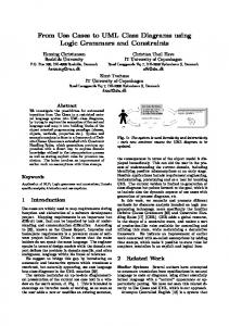
A use case diagram describes how an entity may use the system under development. To this end, a use case diagram contains actors and use cases. An actor is an entity that may interact with the system. A use case is a set of interactions between any number of actors and the system under development. Thus, a use case describes a part of the behavior of the system. An example of a use case diagram is shown in figure 1. The ovals represent use cases, and the puppets represent actors. A line between an actor and a use case represents the actors involvement in one or more of the interactions covered by the use case. When two use cases partly share the same behavior, this behavior may be put into a third use case, and the original two use cases may be defined to ’include’ the behavior of this new use case. The description of the original use cases specifies the point at which to include this behavior. The
Actor
Enter Mortgage
Generalization
Check Credit
+actor
1
Administrative Worker
Draw up Offer
*
Inform about Rejection
+specialization
+parent +base
Use Case
1 +extension
1
+extend
*
*
+extensionpoint
Advisor
*
1
+usecase 1
Association *
Advise
*
+child 1
+generalization
*
ExtensionPoint
1..*
*
1
+include
1
*
1 +addition
*
Include
+base
* Extend
+extensionpoint
Figure 1. Example use case diagram goal of the include relation is to remove redundancy. An include relationship is represented by a dashed arrow, labeled include . When one use case is a generalized form of another use case, we can draw a generalization relationship between them. We could, for example, draw a generalization relationship from the use case ’process complaint’ to the use case ’process incoming mail’. Generalization relationships can also exist between actors. The actor ’employee’, for example, is a generalization of the actor ’administrative worker’. A generalization relationship is represented by a solid line with a hollow arrowhead from the specific to the generic use case or actor. We may describe an extension to a use case’s behavior, that is only carried out under a certain condition. To do this, we define an extension relation between this use case, and the use case that describes the extension. If at a predefined point (an extension point) in the execution of the base use case, a specified condition is met, then the extension use case is carried out. An extension relation is represented by a dashed arrow, labeled extend . Each use case can be described in detail, by describing the interactions between the actors and the system, and the order in which they occur. Many description techniques exist to detail a use case. We could, for example, use state machines [14], activity diagrams [8], or informal text [15]. In this paper we use activity diagrams both for describing use cases in detail and for business process modeling, because this makes the transformation algorithm straightforward. The metamodel of a use case diagram is shown in figure 2. It is a simplified version of the metamodel that can be found in the UML specification [14].
3. Business Process Modeling Many techniques for business process modeling exist. In an earlier study [17], we studied 18 of the most referenced techniques. From this study we were able to draw up a generalized metamodel of business process modeling. Figure 4 presents a simplified version of this metamodel. Although all business process modeling techniques have means to
Figure 2. Use case metamodel Administrative Worker
Advisor
Enter Client Data
Enter Mortgage Data
Check Credit [Not Approved]
[Approved]
Approve Mortgage
Inform Client about Rejection
Advise Client
Process Changes
Check Credit
Draw up Offer
Figure 3. Example business process model
model aspects other than behavior, such as organizational structure, and data objects, we will focus on modeling behavior. The reason for this is that use case diagrams do not have means to model aspects other than behavior. Therefore these aspects can not be mapped, and are thus irrelevant in this paper. A business process model describes the tasks that have to be carried out to reach a certain goal, and the order in which these tasks have to be carried out. A task is the smallest unit of work that makes sense to a user. Each task is assigned to a role. A role is a group of entities that have the same rights and obligations with respect to performing a task or a group of tasks. A role may be assigned to any number of tasks, and an entity may act in any number of roles. In this paper, we use UML activity diagrams to model business processes. Activity diagrams have been shown to be useful for business process modeling in [2, 6]. An example of an activity diagram that models a business process for mortgage processing is shown in figure 3. The rounded rectangles represent tasks, and the arrows represent transitions between tasks. The names in the columns represent roles, and a task in the column of a role represents that this task is assigned to that role. The bullet, and the bulls eye,
Role
Start
End
Model Element
Branch
+responsible 1
*
* +source
1
1
*
*
+destination Task
Guard
Transition
+guard 0..1
1
Figure 4. Business process metamodel represent the beginning and the end of the business process respectively. We can use a guard to model a condition that must be met before starting the next task. A guard could be, for example, ’legal act received’. A guard is graphically represented as a label between square brackets on a transition. We can use a branch to model a choice on the task that has to be started after the current task has finished. A branch has decision criteria attached to it that define under which condition, which task is started. Decision criteria could be, for example, ’if amount ≤ 50, start task A, otherwise start task B’. Decision criteria cannot have overlapping values. A branch is represented by a diamond with one incoming arrow and at least two outgoing arrows. The outgoing arrows have guards attached to them that represent the decision criteria. We can use a fork to model that two or more tasks are started in parallel (i.e. are carried out in random order) after the current task has finished. When two or more tasks are started in parallel, we may want to wait for all tasks to be finished before going on to the next task. This can be achieved by using a join. A fork is represented by an arrow to a thick line, from which arrows leave to the tasks that have to be started. A join is represented by a set of incoming arrows to a thick line, from which an arrow leaves to the task that has to be started next. We chose to disregard the fork and join construct in this paper to simplify the algorithm. Therefore, tasks that are actually carried out in parallel are modeled as if they are carried out in sequence. The fork and join construct can be added in future work.
4. Mapping We created a mapping between the two metamodels by assessing from their definitions, which concepts or relations in the business process metamodel map to which concepts or relations in the use case metamodel. We then defined and evaluated the mapping formally [5]. In this section we give an informal description of the mapping. The mapping is straightforward, except for finding a business process concept that maps to the concept ’Use Case’. We may be tempted to map the ’Task’ concept to the
’Use Case’ concept. However, according to the UML semantics [14], a use case must describe a complete sequence. This means that a use case specifies all the interactions that have to be carried out to bring the system in a state in which the use case can be performed again. A task does not enforce this constraint, and thus does not describe a complete sequence. Therefore, we introduce the ’Step’ concept [12]. A step is a sequence of tasks that can be performed by the same role without interruption. ’Send offer’, for example can be a step. ’Send offer and process reply’ cannot be a step, because time passes between sending an offer and receiving the reply. Since a step is a sequence of tasks that can be performed by the same role without interruption, users experience a step as a unit of work that is completed when it ends, after which it can be performed again. Therefore, a step does describe a complete sequence, and can be mapped to a use case. We map ’Role’ to ’Actor’, and the association between a step and a role to an association between the corresponding actor and use case. Since all tasks in a step are performed by the same role, a role and a step are associated when the role is associated to any of the tasks in the step. Since a step is defined as a sequence of tasks, each step forms a sub-diagram of the original business process model. Because we decided that use cases are described in detail by activity diagrams, we can use the sub-diagrams that are formed by the steps, to detail the use cases that correspond to these steps. Also, we call the tasks that detail a use case: interactions, because a use case model a sequence of interactions between the system and its users. The definition of the mapping leads to an integrated metamodel that contains both the use case and the business process metamodel. Figure 5 shows this integrated metamodel. To keep the figure simple, it does not show include, extend, or generalization relations between use cases. However, these relations are part of the integrated metamodel. We chose to represent a mapping from concept A to concept B by an inheritance relation from B to A. A mapping between two associations can be represented as an OCL constraint. For example, the mapping between the association between step and role, and the association between use case and actor, can be represented by the following OCL constraint: context Step inv : self .association.actor → includes(self .responsible) We also need an OCL constraint that expresses that steps can not contain steps: context Step inv : self .contains → excludesAll(Step.allInstances)
Guard
+guard 0..1
Transition
1
Start
* +contains *
*
1
1
End +source Role
+destination
Model Element +responsible 1
*
*
Branch 1..*
Actor
+actor
+contains
Step
Task
1
* Association
+usecase *
Use Case
1
Figure 5. Integrated Metamodel
5. The Transformation Algorithm From the mapping that we defined in the previous section, we derived an algorithm to transform a business process model into a use case diagram. In this section we will explain this algorithm. The algorithm is based on an algorithm to create steps from tasks [16]. To develop the algorithm, we assume that a set of instances exists for each concept in the integrated metamodel. We also assume that a new operator exists, which adds a new instance to the set of instances of the concept that follows the operator, and returns this instance. For example, new Step adds a new step to steps, and returns this it. The algorithm should start by identifying the tasks that denote interactions with the system under development, because only these tasks are interesting from a use case point of view. In this section we assume that interactions have already been defined, and we refer to [5] for an elaborate discussion on this topic. After the interactions have been identified, we do the following. First, we create an actor for each role in the business process model. actors = roles Second, we create steps around the tasks in the business process model. Initially we create steps around the tasks that are in the same role and can be reached directly from a start state. We add start states to the created steps to denote where they can start. steps = EmptySet foreach r in roles do if exists m in modelElements where r = m.responsible and exists tr in transitions where tr.destination = m and tr.source in start then Step newS = new Step Start newSt = new Start newS.contains += {newSt} newS.responsible = r
foreach m in modelElements do if r = m.responsible then foreach tr in transitions do if tr.destination = m and tr.source in start then Transition newTr = new Transition newTr.source = newSt newTr.destination = m newTr.guard = tr.guard newS.contains += {newTr, m} newTr.processed = True fi od fi od fi od Each step is then extended with the model elements that: (1) have the same responsible role as the step, and (2) can be reached from model elements within the step, and (3) can be performed without waiting. We assume that each transition has a property timepassing that denotes if time passes before the transition can be made. This allows us to check (3). The user of the algorithm must define the value of this property for each transition. If a transition points to a model element with a different responsible role or time passes on a transition, then the transition points to a model element in another step. If this step was not yet created, then it will be. If the step was already created, but there exists no start state in this step that has a transition to the model element, then a start state and a transition from this start state to the model element have to be added. This procedure is repeated until no new steps are added, and the steps themselves also do not change anymore. oldsteps = EmptySet while oldsteps != steps do oldsteps = steps foreach s in steps do foreach tr in transitions do if tr.source in s and !tr.processed and tr.destination !in end then if !tr.timepassing and tr.destination.responsible = s.responsible then s.contains += {tr.destination, tr} tr.processed = true else if tr.destination !in steps.contains then Step newS = new Step newS.responsible = tr.destination.responsible Start newSt = new Start Transition newTr = new Transition
newTr.source = newSt newTr.destination = tr.destination newTr.guard = tr.guard newS.contains += {newSt, newTr, tr.destination} tr.processed = true newTr.processed = true else if !exists tr’ in transitions where tr’.source in start and tr’.destination = tr.destination then Start newSt = new Start Transition newTr = new Transition newTr.source = newSt newTr.destination = tr.destination newTr.guard = tr.guard tr.destination.step.contains += {newSt, newTr} tr.processed = true newTr.processed = true fi fi fi fi od od od
up some use cases into a base use case and an extension or addition use case, or into one generalized and multiple specialized use cases. Third, according to its definition a use case delivers a result of value to its user. However, in the case studies we found situations in which users experienced that a use case only delivered a result of value when it was combined with another use case. This situation can be solved by verifying if each use case delivers a result of value to its users, and, if not, by combining it with other use cases such that it does. Fourth, the choice to describe use cases that belong to the same business process in one use case diagram suggests that each system is built for only one business process. Also, it suggests that only one system is built for each business process. However, this is rarely the case. A client database, for example, is usually used by all primary business processes. Therefore, once a use case diagram is drawn, there must be evaluated which use cases will be implemented by which system. This decision will be based on what systems already exist to support other business processes. When we decide that a use case is partly implemented by one system, and partly by another system, we may decide to split the use case. Eriksson and Penker describe a procedure for doing this in [7]. Fifth, the algorithm does not add end states to the activity diagrams that detail the use cases. To be complete, we should add end states to these diagrams.
Third, we create a use case for each step that we identified. Also, we create an association between an actor and a use case when an association exists between the role that corresponds to the actor, and a step that corresponds to the use case.
In a case study, we applied the algorithm in practice, and evaluated the quality of the resulting use case diagrams, by comparing them to use case diagrams that were constructed from scratch. From the results we derived some recommendations that were incorporated in the restructuring step of the algorithm. In the case study, we investigated a total of 6 business processes, from which we derived 42 use cases. When comparing the use case diagrams, 17 use cases contained improper constructs: of 2 use cases some of the tasks were defined more than once, 3 use cases were completely redundant, and 12 use cases only delivered a result of value in combination with another use case. We corrected these errors by introducing the restructuring actions that are described in the previous section. A simplified example that shows how a business process model was transformed into a use case diagram during the case study is shown in figure 6. The figure shows two of the use cases that result from applying the algorithm to the business process model from figure 3. It shows how each use case is detailed by an activity diagram that is a part of the original diagram. It also shows the transitions that contain information about the relations between the use cases, but that are not part of the use cases themselves. These transitions may be used later on to build a system that controls the order in which the use cases may occur (such as a workflow engine).
usecases = steps foreach s in steps do Association newA = new Association newA.actor = (Actor) s.responsible newA.usecase = (UseCase) s od Fourth, we restructure the use case diagram that results from applying the algorithm. This can be done according to normal restructuring rules, like, the ones described in [9]. However, when using the algorithm, some constructs need special attention. Therefore, we will point out some restructuring actions that are normally necessary when using the algorithm. Due to space limitations, we only discuss the restructuring rules informally, and do not give their algorithmic implementation. First, we found out that tasks are often described multiple times. The reason for this is that business process modeling techniques do not cater for reuse of tasks. However, in use case diagrams reuse is possible by means of the include relation. Therefore, we search the use cases for interactions that are defined more than once. We put these interactions in a separate use case, and we draw an include relation from the original use cases to this separate use case. Second, the algorithm does not cater for inclusion, extension or generalization of use cases. Therefore, it may be useful to split
6. Case Study
7. Conclusion In this paper we introduced an algorithm to transform business process models into UML use case diagrams. The algorithm is
Enter Mortgage Data
Check Credit
Enter Client Data Approve Mortgage
Administrative Worker Enter Mortgage
[Mortgage Not Approved]
[Mortgage Not Approved] Inform Client about Rejection Advisor Inform about Rejection
Figure 6. Resulting Use Case Diagram based on a formal mapping between the metamodels of the two modeling techniques. We have shown in a case study that the application of the algorithm results in use case diagrams that can serve as a basis for further system development. We can, for example, use the unified process [9] that takes use case diagrams as a starting point and develops software from them. The study described in this paper is related to the fields of requirements, and method engineering. Much work is done in both fields to study how models of different types can be generated from each other. Research is done to how business processes can be described using use case diagrams [13, 9, 10, 14]. We, however, do the opposite, and use business processes to derive use cases. Eriksson and Penker describe a procedure to derive use cases from business processes that is similar to ours in [7]. However, this procedure is less detailed. The use case diagrams that result from the application of the procedure have limitations. First, the use case diagrams specify a typical information system, in the sense that they do not specify control information that is above step level. For example, the use case diagram from figure 1 does not specify whether client data must be entered before mortgage data or not. When we want to specify this type of control information, a service, such as a workflow engine, has to be built on top of the information system that is specified by the use case diagrams. Second, the use case diagrams are as detailed as the business processes from which they have been derived. A use case may, for example, contain the interaction ’enter client data’, or the interactions ’search client based on name and date of birth’, if the client was not found ’create a new client’, and ’enter name, address, and date of birth of the client’. The second set of interactions provides a more precise specification than the first set of interactions. Therefore, depending on the amount of detail specified in the business processes, it may be necessary to perform interviews with system users to detail the use case diagrams further. The extend to which this is a problem can not be assessed from one case study.
References [1] B. Boehm. Software Engineering Economics. Prentice Hall, Englewood Cliffs, 1981. [2] G. Booch, J. Rumbaugh, and I. Jacobson. The Unified Modeling Language User Guide. Addison-Wesley, Reading, MA, 1999. [3] A. Cockburn. Structuring use cases with goals. Journal of Object Oriented Programming, 10(7):35–40, 1997.
[4] A. Cockburn. Structuring use cases with goals. Journal of Object Oriented Programming, 10(8):56–62, 1997. [5] R. Dijkman and S. Joosten. Deriving use case diagrams from business process models. Technical Report 02-08, CTIT, Enschede, The Netherlands, 2002. [6] M. Dumas and A. ter Hofstede. UML activity diagrams as a workflow specification language. In M. Gogolla and C. Kobryn, editors, Proceedings of the UML 2001 Conference on Modeling Languages, Concepts and Tools, volume 2185 of Lecture Notes in Computer Science, pages 76–90, Berlin, 2001. Springer. [7] H.-E. Eriksson and M. Penker. Business Modeling with UML: Business Patterns at Work. Wiley, New York, 2000. [8] M. Fowler and K. Scott. UML Distilled: Applying the Standard Object Modeling Language. Addison-Wesley, Reading, MA, 1997. [9] I. Jacobson, G. Booch, and J. Rumbaugh. The Unified Software Development Process. Addison-Wesley, Reading, MA, 1999. [10] I. Jacobson, M. Ericsson, and A. Jakobson. The Object Advantage: Business Process Reengineering with Object Oriented Technology. Addison-Wesley, Reading, MA, 1994. ¨ [11] I. Jakobson, M. Christerson, P. Jonsson, and G. Overgaard. Object Oriented Software Engineering: A Use Case Driven Approach. Addison-Wesley, Workingham, 1992. [12] S. Joosten, G. Aussems, M. Duitshof, R. Huffmeijer, and E. Mulder. An Emperical Study about the Practice of Workflow Management. University of Twente, Enschede, The Netherlands, 1994. [13] S. Nurcan, G. Grosz, and C. Souveyet. Describing business processes with a guided use case approach. In Proceedings of the 1998 Conference on Advanced Information Systems Engineering, volume 1413 of Lecture Notes in Computer Science, pages 339–362, Berlin, 1998. Springer. [14] OMG. OMG unified modeling language specification version 1.4. Technical Report formal/2001-09-67, OMG, 2001. [15] J. Rumbaugh, I. Jacobson, and G. Booch. The Unified Modeling Language Reference Manual. Addison-Wesley, Reading, MA, 1999. [16] J. van Beek. Generation workflow: How staffware workflow models can be generated from protos business models. Master’s thesis, University of Twente, Enschede, The Netherlands, 2000. [17] W. van Dommelen, S. Joosten, and M. de Mol. Comparative study to aids for managing business processes (in dutch: Vergelijkend warenonderzoek hulpmiddelen beheersing bedrijfsprocessen. Technical report, Department of Finance, The Hague, The Netherlands, 1999.