AMULET2e: An Asynchronous Embedded Controller STEPHEN B. FURBER, JAMES D. GARSIDE, PETER RIOCREUX, STEVEN TEMPLE, PAUL DAY, JIANWEI LIU, AND NIGEL C. PAVER Invited Paper
AMULET2e is an embedded system chip incorporating a 32-bit ARM-compatible asynchronous processor core, a 4-Kb pipelined cache, a flexible memory interface with dynamic bus sizing, and assorted programmable control functions. Many on-chip performance-enhancing and power-saving features are switchable, enabling detailed experimental analysis of their effectiveness. AMULET2e silicon demonstrates competitive performance and power efficiency, ease of system design, and it includes innovative features that exploit its asynchronous operation to advantage in applications that require low standby power and/or freedom from the electromagnetic interference generated by system clocks. Keywords— Asynchronous logic circuits, CMOS digital integrated circuits, digital systems, electromagnetic compatibility, integrated circuit design, microprocessors.
I. INTRODUCTION Nearly all digital system design today is based upon the use of a clock to control the rate of operation and the flow of information within the system. There may be different clocks in different subsystems (for instance, the graphics subsystem may use a different clock from the processor), but the basis of the design methodology is that large areas of logic operate within the same clock domain and the interfaces between the domains of different clocks are localized and treated separately. The clock is sometimes even apparent to the user; all but the most naive PC users know that a P200 Pentium is faster than a P166 Pentium and the number indicates some sort of clock rate. The clock has not always enjoyed dominance in digital designs. Many of the earliest computers operated without a central clock, employing “asynchronous” design techManuscript received December 1, 1997; revised August 20, 1998. This work was supported by CEC as part of ESPRIT Project 6909, OMI/DEARM (the Open Microprocessor Systems Initiative—Deeply Embedded ARM Applications Project) and by ARM Ltd. S. B. Furber, J. D. Garside, P. Riocreux, and S. Temple are with the Department of Computer Science, University of Manchester, Manchester M13 9PL U.K. (e-mail:
[email protected]). P. Day is with 2n Design Ltd., Manchester M21 0DN U.K. J. Liu and N. C. Paver are with Cogency Technology, Inc., Cheshire SK8 1HX U.K. Publisher Item Identifier S 0018-9219(99)00880-4.
niques. However, asynchronous design gained a reputation for being difficult and unreliable, and the advent of integrated circuits increased the need for reliability to the extent that any risk that could be removed should be removed, including any asynchronous operation. Thus the dominance of the clock was established. For the last quarter of a century asynchronous design has been of mainly academic interest, playing little part in industrial electronics. Now, however, we are poised on the brink of a revolution. Asynchronous design is reemerging from academia with a new look, with new answers to the old problems of design difficulty and unreliability. At the same time, clocked design is running into trouble. There is now a significant prospect of asynchronous design returning to industrial use in the next few years. A. Motivation for Asynchronous Design Since the clock has been so successful in enabling the digital revolution over the last 50 years, why should we even consider abandoning it? Several arguments can be made, but the two that most influence the AMULET work are electromagnetic compatibility (EMC) and power efficiency. Both of these are very important factors in the rapidly growing market for mobile communication devices such as pagers, cellular telephones, etc. 1) EMC: Clocked control is the worst possible approach for EMC. CMOS circuits only draw current when they switch, and clocked synchronization means that all the circuits on the chip switch at the same time, maximizing the current transients, which in turn maximizes the radio interference. Furthermore, high-precision crystal controlled oscillators focus the energy into very narrow spectral peaks on harmonics of the fundamental clock frequency. Asynchronous circuits, on the other hand, distribute activity over time as each part of the circuit becomes active in response to inputs from another. Therefore the circuit does not have the large current peak at a fixed point in every clock cycle of a synchronous circuit, rather it has a distribution of smaller peaks which result in a lower
0018–9219/99$10.00 1999 IEEE PROCEEDINGS OF THE IEEE, VOL. 87, NO. 2, FEBRUARY 1999
243
radiated power. Furthermore, the activity is not locked to a particular frequency, and although many asynchronous circuits have characteristic cycle times, these are averages and individual cycles vary considerably from the average. Therefore there is much less concentration of the power into spectral peaks, and what radiated power there is spreads across the frequency spectrum more evenly. 2) Power Efficiency: Clocks cause unnecessary power dissipation by generating activity in parts of the circuit that are doing no useful work. Merely distributing a highfrequency, low-skew clock consumes significant power. Clock gating can reduce the unnecessary activity, but only at a coarse granularity, and although software power management techniques are effective, it clearly costs power to run the power-management software itself. Asynchronous circuits are inherently data driven and only consume power when there is useful work to do. As we shall see, an asynchronous circuit can switch instantly between zero idle power and maximum throughput without software assistance, giving better power efficiency than sophisticated working/idle/sleep power management schemes, and with no software overhead. B. Asynchronous Microprocessors This paper focuses on the AMULET asynchronous microprocessors developed at University of Manchester, U.K. Related work on the design of clockless very large scale integration (VLSI) processors has taken place under the leadership of Martin at California Institute of Technology (Caltech), where the first fully asynchronous VLSI microprocessor [1] was developed in the late 1980’s. More recently they have developed an asynchronous implementation of the MIPS R3000 [2]. An asynchronous 8-bit microprocessor, TITAC, has been developed at the Tokyo Institute of Technology [3] under the leadership of Nanya, and more recently he has led the development of TITAC-2 [4], a 32-bit asynchronous microprocessor with an instruction set based on the MIPS R2000. An asynchronous 8051 microcontroller has been produced by Eindhoven University of Technology and Philips Research Labs [5]. Work on the design of asynchronous processor organizations not yet leading to VLSI prototypes has taken place at Sun Research Laboratories [6], University of Utah [7], University of Cambridge [8], University of Hertfordshire [9], Technical University of Denmark [10], France Telecom-CNET [11], and other places. C. The AMULET Processors While asynchronous design is enjoying increasing attention from the academic community and initial stirrings of interest from industry, its progress toward realizing its full commercial potential continues to be impeded by a shortage of large-scale demonstrations of merit. For the last seven years the AMULET group at University of Manchester has spent most of its energies addressing this shortfall and gaining experience of asynchronous engineering “in the large.” The first milestone in this work was reached in 1995 with the delivery of AMULET1 [12], [13], an asynchronous 244
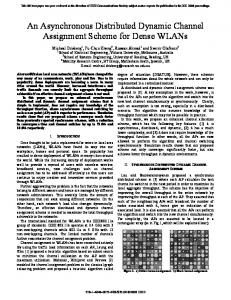
Fig. 1. Two-phase bundled-data communication.
implementation of the ARM [14] 32-bit reduced instruction set computer (RISC) microprocessor which used a twophase bundled-data design style based closely on Sutherland’s micropipelines [15]. The basic concepts of two-phase bundled data are: • transition (two-phase) signaling, where a change in logic level is used to signal an event; rising and falling events are equivalent in their interpretation; • bundled data, where a conventional data bus carries binary data whose validity is indicated by a transition on a request wire and whose reception is indicated by a transition on an acknowledge wire. The resulting communication protocol is illustrated in Fig. 1, which shows two consecutive communications using first rising and then falling transitions on the request and acknowledge events. AMULET1 was broadly comparable with, but not superior to, clocked ARM processors built on the same technology, fulfilling its primary role of demonstrating the feasibility of designing complex asynchronous circuits with the resources and tools available to the group. It also taught us a great deal about practical asynchronous design both from the things that we got right and from the things we got wrong. The second milestone in this work has now been reached. AMULET2e is an asynchronous embedded controller incorporating AMULET2 (a significantly enhanced version of AMULET1), 4 Kb of RAM which can be configured to operate as a cache, a flexible memory interface which makes the system designer’s job look quite conventional, a counter-timer for real-time reference, and various configuration and control registers. First silicon arrived on October 1, 1996, having passed functional tests at the foundry (VLSI Technology, Inc.) without difficulty, and within a few hours a sample was communicating with the standard ARM development tools and running compiled C programs. The parts are highly functional, perform exactly as predicted by our simulation tools, and have the sort of performance and flexibility that will attract applications developers to look again at asynchronous technology. In Section II we review AMULET1, looking particularly at the lessons we learned from it which influenced the design of AMULET2e. Then the AMULET2 processor core is described in Section III. In Section IV we present the organization of AMULET2e, and in Section V we present a simple system designed around the part. In Section VI we describe the tools used in the development of AMULET2e. In Section VII we give a summary and analysis of the test results and we draw our conclusions from the work in Section VIII. PROCEEDINGS OF THE IEEE, VOL. 87, NO. 2, FEBRUARY 1999
Fig. 2.
AMULET1 internal organization.
This paper is an extended and updated version of a paper [16] first presented at the 3rd International Symposium on Advanced Research in Asynchronous Circuits and Systems which was held in Eindhoven, The Netherlands, on April 7–10, 1997. II. AMULET1 The AMULET1 organization has been described elsewhere [12], [13], [17]–[20], so only a summary is presented here. The processor-to-memory interface follows the micropipeline convention in that it uses two-phase bundled data communication as described earlier, with one (output) bundle to send address, control, and write data to the memory and a second (input) bundle to return read data from the memory. The memory system may have an arbitrary pipeline depth and delay, but it must return read values in the requested order. Internally the processor may be viewed as comprising several pipeline units (Fig. 2) which operate independently and concurrently, exchanging information through bundleddata interfaces. The role of each of these units is described briefly below. The memory pipeline is also shown in Fig. 2 because, while the memory array is external, memory control information (such as whether the fetch was instruction or data) is kept on chip. 1) Address Interface: The address interface [13] is responsible for issuing read and write requests to memory. It issues instruction prefetch requests autonomously and accepts data transfer and branch target addresses from the execution unit as required. Branch target addresses are immediately issued to memory and also change the prefetching stream to continue from the target location; data-transfer addresses temporarily interrupt the prefetching stream, which resumes once the data address has been issued. FURBER et al.: AMULET2e: AN ASYNCHRONOUS EMBEDDED CONTROLLER
The ARM architecture makes the program counter readily accessible to the programmer as register 15 in the register bank. PC values are therefore copied from the address interface to the register bank through a PC pipeline that buffers the values until the associated instruction arrives from memory. 2) Register File: All the user-accessible state is held in the register bank, which employs a novel locking mechanism [21] to allow multiple pending writes from the execution pipeline and from external memory. The locking mechanism ensures the correct behavior of instruction streams with data dependencies between successive instructions. It also enables register read and write processes to proceed asynchronously without arbitration and without risk of metastability in the control and data circuits. 3) Execution Pipeline: Arithmetic processing is carried out in the execution pipeline. This incorporates a “3-bits at a time” carry-save multiplier, a barrel shifter and rotator, and an arithmetic and logic unit (ALU). The ALU has a datadependent propagation delay that detects the longest carry chain in an addition [22]. This allows a relatively simple ALU to give better average performance on a typical mix of operand values than the more complex ALU in the clocked ARM6, since there is no need to coerce the worst-case addition into a fixed clock period. 4) Instruction Decoder: The instruction decoder accepts instructions from the instruction pipeline and generates the necessary control signals to pass to the register file and to the execution pipeline (via the control pipeline, where some further decoding takes place). The major decode function of the instruction decoder is implemented by a large programmable logic array (PLA), but there are other complex control functions (such as splitting a single ARM instruction into several execution pipeline operations) that lead to considerable complexity in this area. A. AMULET1 Lessons AMULET1 was a major design project that had to be completed with limited resource and within a limited time. It clearly solves all the problems that must be solved to implement a functional asynchronous microprocessor, but the solutions are not all equally good. In some areas we consider that we have found solutions which are elegant and efficient. • The (patented) register locking mechanism [21] works efficiently and well. Although it is desirable to avoid stalls by bypassing when possible (which AMULET1 made no attempt at, though AMULET2 does), the totally dependable consistency offered by this mechanism has stood up well through the developments that followed. • The instruction prefetching with its “color” management of nondeterminism [12], [13] has also scaled well. The nondeterminism is a potential source of difficulty for test vector generation, but otherwise it solves a tricky problem in a straightforward and efficient manner. 245
Fig. 3.
Four-phase bundled-data communication.
• The overall organization based on interacting micropipelines has proven reasonably straightforward to design and optimize. Against these positive lessons, there were a number of experiences with AMULET1 that we wished to avoid repeating. • Although micropipelines worked well on chip, they proved very troublesome at board level. AMULET1 is a basic processor core with a two-phase micropipeline interface at the pins, and debugging the logic which handled these two-phase signals took a long time—it took almost a month from receiving the first silicon before we knew that the chips were basically functional. • Two-phase design is conceptually straightforward, but our CMOS implementations of two-phase control elements were somewhat inefficient. All pipeline registers had two- to four-phase conversions inside them, and all dynamic logic structures needed four-phase conversions also. Even where four-phase control is not required, steering two-phase signals (which are edges) requires circuits with state and exclusive OR gates gates, since CMOS is fundamentally a level-sensitive technology. • Building deep pipelines in a micropipeline circuit is too easy. The AMULET1 execution pipeline is deeper than is useful, and performance is lost as a result. (It is actually quite hard to balance asynchronous pipelines; against this, they are very flexible and often self-adapt to varying load conditions.) III. AMULET2 These lessons formed the starting point for AMULET2. A four-phase bundled-data design style was adopted [23], a little more care was taken over the pipeline depths, and a lot more attention was paid to the system interface at the chip pins. In addition, several architectural features were added to improve the performance and power efficiency of the device. These are described below. The four-phase bundled-data style differs from the twophase style in that whereas the latter uses both rising and falling transitions to carry the same information, the fourphase style uses one of the edges as the active edge and requires a return-to-zero phase before the next communication can begin. The four-phase communication protocol is illustrated in Fig. 3. A. Pipeline Reorganization As was mentioned above, a retrospective analysis of the AMULET1 design revealed that the depth of pipelin246
(a)
(b)
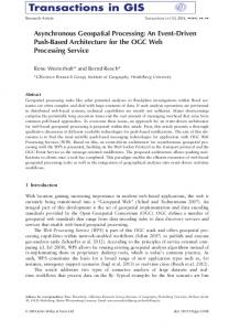
Fig. 4. (a) AMULET1 and (b) AMULET2 execution pipelines.
ing is too great. This is partly due to first-in first-out (FIFO) buffers being conceptually easy to use within the micropipeline design style, and as a result too many were added. There are many stages that contribute little (or nothing) toward performance but still cost silicon area, transistors and power dissipation, and some stages actually decrease performance! This analysis identified the main execution pipeline as a candidate for pipeline simplification. The ARM architecture specifies that the shifter can be used to shift one of the operands in many of the instruction classes. However, in practice most shift operations are performed on immediate values, and this can be done before the immediate value is passed to the execution pipeline, in parallel with reading the register bank. This, coupled with the fact that a high percentage of instructions do not take advantage of the shift operation at all, means that there are performance and power gains to be achieved by bypassing the shifter when it is not in use (which is most of the time). Fig. 4 shows a comparison of the AMULET1 and AMULET2 execution pipeline structures with the AMULET2 pipeline showing the shifter bypass route through the multiplier. (The multiplier contains an internal bypass mechanism, so if neither the shifter nor multiplier is to be activated the internal multiplier bypass path is used.) The shifting of immediate values is performed elsewhere in order to exploit this pipeline organization fully. Now that the shifter and multiplier are bypassed for most operations, there is little justification for providing a separate pipeline stage for them. This also facilitates the ALU register forwarding scheme (described in Section IIIB) where the last result value only has to propagate backward across a single pipeline stage. The last difference between the two execution pipeline organizations is that the final result latch has been replaced PROCEEDINGS OF THE IEEE, VOL. 87, NO. 2, FEBRUARY 1999
Fig. 5.
LRR control algorithm.
with latches inside the register bank and address interface. This reduces the time that the write bus (a shared resource) is busy for a given write-back operation and reduces arbitration clashes between the ALU and data interface, thus improving performance. B. Register Forwarding The register management scheme in AMULET1 provides an effective mechanism for ensuring register coherency. However, the locking mechanism employed causes the pipeline to stall when any register dependency is detected; processing only continues when the required value has returned to the register bank. This stall encompasses the entire register write–unlock–read sequence. Conventional synchronous processors overcome this problem by using register forwarding. However this relies on global synchronization; enforcing any pipeline synchronization in an asynchronous processor destroys any advantage gained. AMULET2 therefore uses the concept of last result registers to achieve similar results. Two schemes are employed in AMULET2: the ALU last result register (LRR) is used when the result calculated by the ALU is required as an operand by the next instruction; the last loaded value (LLV) register is used when the operand being loaded from memory is required by one of the following instructions. The control mechanism and validity of the data is different for the two types. Both mechanisms can be disabled independently if required, allowing their effectiveness to be measured. 1) ALU LRR: The ALU last result mechanism divides into two distinct parts: the LRR itself and the control to indicate when to use the value in the LRR. The LRR itself is simply a transparent latch in anti-phase to the ALU result latch. Whenever the ALU is activated the previous value is automatically available on the LRR. Its associated control (see Fig. 5) keeps a record of the destination register of each instruction and compares this with the operand addresses of the subsequent instruction. If the comparison matches and the LRR value is valid (not all instructions produce usable results) then the register bank read is bypassed and the data are retrieved from the LRR—which must be valid before the instruction is allowed to arrive—via a set of multiplexers (see Fig. 6). As the LRR is in anti-phase with the ALU output latch its value is only valid for the next instruction. As soon as FURBER et al.: AMULET2e: AN ASYNCHRONOUS EMBEDDED CONTROLLER
Fig. 6. Register forwarding organization.
the next instruction passes through the ALU the LRR is automatically updated with the new last result value. 2) LLV: The LLV mechanism also divides into data and control partitions. The LLV register is updated with a load data value directly from the processor write bus every time a data value returns from memory to the register bank. The value in the LLV is therefore valid from when the data arrive from memory until the next update of the LLV (another load returning data from memory) or an ALU operation renders the cached register value in the LLV invalid by writing to the same destination register. The value in the LLV can therefore be valid for a number of consecutive instructions (in contrast to the ALU last result, where the validity of the data is from one instruction to the next only). The control of the LLV is considerably more complex than the ALU last result due to two key “features”: • the validity of the LLV must be managed explicitly rather than automatically being taken care of as for the ALU last result; • the LLV cannot be used until the value has returned from memory, and there may be multiple outstanding load operations. In the ALU last result, the value is available immediately in the ALU if the control indicates forwarding is possible. The first “feature” can be addressed by additional decode logic to detect instructions which would invalidate the LLV prematurely (for example, an ALU operation with the same destination register as the value stored in the LLV). The second “feature” is more complex. An instruction wishing to use the LLV value must somehow synchro247
nize with the returning value. Unfortunately the returning memory data does not know that it should be forwarded to the LLV as the load was dispatched before the following instruction detected a data forwarding opportunity. Therefore explicit synchronization is not practical. A semaphore technique based upon the lock FIFO [21] principle can be used to solve the problem. Every issued load places a token in a FIFO (increment). Every data value that returns is copied into the LLV register (overwriting any previous value) and a token is removed from the FIFO (decrement). An instruction that wishes to use the LLV must wait until the FIFO is empty before taking the value and proceeding. The empty FIFO state confirms that the value in the LLV register is truly the “last” value and not some preceding value. Note that all three semaphore operations (increment, decrement, and read) are independent and asynchronous. 3) Forwarding Issues: Both forwarding mechanisms gain performance by bypassing a register bank read operation (and potential stall), so an instruction that uses forwarding must be sure that the value will, indeed, become available. A feature of the ARM instruction set [14] is that every instruction has a conditional guard on its execution; if the condition test fails it will produce no result. Therefore only the results of instructions with the guard “ALWAYS” (that is, instructions that are unconditionally executed, which typically represent 70% of all instructions) are guaranteed to be available and only these results may be used for forwarding. In all other cases the instruction must fall back on the register locking mechanism to ensure it gets the correct operand values. Since there is always a fall-back mechanism, the forwarding logic only serves to improve performance. There is little performance benefit from forwarding for infrequently used instructions, so the decoder can take a conservative approach and only attempt to use the forwarding mechanism for frequently used instruction classes. C. The Branch Target Cache (BTC) AMULET1 prefetches instructions sequentially from the current PC value and all deviations from sequential execution must be issued as corrections from the execution pipeline to the address interface. Every time the PC has to be corrected performance is lost and energy is wasted in prefetching instructions that are subsequently discarded. AMULET2 attempts to reduce this inefficiency by remembering where branches were previously taken and guessing that control will subsequently follow the same path. The organization of the BTC is shown in Fig. 7; it is similar to the “jump trace buffer” used on the MU5 mainframe computer [24] developed at University of Manchester between 1969 and 1974 (which also operated with asynchronous control). The BTC caches the addresses and targets of 20 recently taken branch instructions and modifies the predicted control flow to the previous branch target whenever it spots an instruction fetch from a stored address. When this prediction is correct, exactly the right instruction sequence is fetched. When it is wrong, the correction mechanism 248
Fig. 7. BTC organization.
(an “unbranch”) has the same cost as an unpredicted taken branch. Note that the branch prediction operation is entirely local to one pipeline stage in the address incrementer loop; it requires no information about (for example) the fetched instruction. The only external synchronization occurs following a misprediction (unpredicted branch or “unbranch”) in which case an interruption of the prefetch is necessary anyway. This led us to choose this approach over the many other branch prediction schemes used in clocked processors. Although not shown in Fig. 7, the flow of data required to update the cache is almost as convenient. The cache is updated when an unpredicted branch is taken. When this happens, the execution stage calculates the branch target by adding an offset to the PC and then passes the result along with the PC to the address interface. These are exactly the values required to update the BTC. A good way to think about the BTC is to view the incrementer in AMULET1 as a first-order next instruction address predictor and the BTC as a second-order correction unit. They occupy exactly the same pipeline slot in the address interface and work in parallel, with the BTC having priority whenever it recognizes the input address. When the prediction is correct the instruction flow is smooth; when it is wrong recovery is necessary. In AMULET1 the prediction is wrong whenever a branch is executed, and recovery is performed by executing the branch. In AMULET2 the prediction is wrong when an unpredicted branch is executed (recovered by executing the branch) or when a branch is predicted in error (which is recovered by executing an “unbranch”). 1) BTC Implementation: Since the BTC performs a lookup on every instruction address issue it is important that it consumes minimal power. Its basic structure is that of an associative memory, and for performance reasons the associative store is built from content-addressable memory (CAM) which tends to be power hungry. To reduce its power consumption the CAM is divided into two sections (see Fig. 8): the larger section takes all of the address apart from a few low-order bits; the smaller section deals with these low-order bits. Since most instruction fetches run PROCEEDINGS OF THE IEEE, VOL. 87, NO. 2, FEBRUARY 1999
Fig. 9. AMULET2e internal organization.
Fig. 8.
BTC internal structure.
sequentially, the high-order bits change rarely and the high section of the CAM need not be activated (provided that its last output was stored). Therefore only the small section of the CAM is active on every cycle. This segmentation of the CAM saves around 70% of the power consumption of the CAM; it also reduces the average lookup time, improving performance. The RAM part of the BTC is only activated when there is a hit in the CAM, so its contribution to the overall power consumption is small. Despite careful design the BTC will still consume some power. However, it should also reduce the total number of instruction fetches, improving performance and saving power in the cache and/or external memory, so with careful design it should save system power overall. D. “Halt” Most ARM programs, when they run out of useful work to do, enter an idle loop implemented as “B.” where an instruction continuously loops back to itself until an interrupt occurs. (The ARM instruction set does not include an explicit halt instruction.) Since this idle looping wastes power, AMULET2 detects this instruction and a mechanism stalls a control loop in the execution pipeline. The stall rapidly propagates throughout the system, halting all activity. An interrupt causes an immediate resumption of processing at maximum performance. IV. AMULET2e AMULET2e is an asynchronous embedded system controller incorporating an AMULET2 core, as described above, along with a cache/RAM, a flexible memory interface, and various control functions (including a timer/counter that will typically be driven from a 32-kHz crystal oscillator). Its internal organization is illustrated in Fig. 9. A. The AMULET2e Cache The cache [25] is 4 Kb of RAM divided into four 1-Kb blocks, each block having an associated 64-entry tag FURBER et al.: AMULET2e: AN ASYNCHRONOUS EMBEDDED CONTROLLER
CAM. When configured to operate as a cache (it may, alternatively, operate as a memory mapped RAM) the tag and data accesses are pipelined. The cache is 64-way associative with a quad-word line. Refill is addressed-word first [26] and the processor may continue accessing other cache locations while the refill completes (“hit under miss”) although a second cache miss must wait for the first line fetch to complete. Refill data are held in a line-fetch latch until the next cache miss, so an additional CAM entry identifies subsequent hits on the line-fetch latch. The CAM and RAM are self-timed for asynchronous operation using dummy matched paths, and the organization incorporates a number of power-saving features: • sequential accesses within a line bypass the CAM lookup (this also improves performance); • the RAM sense amps do not turn on until the differential data are almost ready, and they turn off as soon as the value has been sensed; • only the addressed 1-Kb block is activated in any access—the other blocks remain inactive and consume no power. B. The Memory Interface Perhaps the most forceful lesson from AMULET1 was the need to make the memory interface easier to use. AMULET2e presents a relatively conventional interface to the system designer, with a bidirectional data bus, an address bus, and a range of chip select lines. The ARM 32-bit address space is divided into eight regions which can be configured independently for bus width, memory “type,” and access timing; external memory may be 8-, 16-, or 32-bits wide. For example, this allows the system to boot from a single, slow 8-bit ROM but use fast 32-bit SRAM for its main memory. Alternatively (or additionally) a variety of DRAM devices are supported with the address multiplexing and control sequencing supported on-chip; page mode is used if the processor or cache indicates that sequential addresses will be forthcoming (such as a cache line fill or a multiple register stack push). The objective here was to provide the system designer with maximal flexibility. Full details of the memory configuration options are available in the AMULET2e data sheet [27]. 249
Fig. 10.
AMULET2e test card organization.
Since it is unreasonable to require external memory and peripheral components to provide completion signals (at least until asynchronous design has wider commercial support), some mechanism must be provided to ensure that the timing requirements of these components are met. In a clocked circuit, the period of a crystal oscillator provides a very reliable reference for this purpose, but we wish to avoid the power overhead of running an oscillator at memory speeds. The solution adopted on AMULET2e is to provide a “reference delay” and to program all external accesses in multiples of this delay. Since on-chip delays are subject to process variation, the reference delay is off chip. It may be a simple RC delay, an integrated delay line, or a silicon delay line. If DRAM’s are used, one absolute timing reference is required to ensure that the RAM is refreshed. This is provided by the 32-kHz crystal oscillator, which provides regular (if infrequent) requests for refresh to the memory interface. These requests are arbitrated with any other requests by the interface itself, thus refresh will proceed with or without other bus activity, even if the processor is halted. V. AMULET2e SYSTEM DESIGN At board level, the chip is conventional and building a system is straightforward. The flexible memory interface results in a very low chip count. As an example, Fig. 10 shows how the AMULET2e equivalent of the ARM “PIE” (platform independent evaluation) card is designed. An 8-bit ROM holds the “Demon” debug monitor code, which is unchanged from the PIE ROM apart from a few instructions used to configure the various memory regions. One location in the ROM is used by the AMULET2e hardware to configure the region occupied by the ROM itself so that the system can bootstrap. Four 8-bit SRAM chips provide the main memory. The system can operate with one or two RAM’s, but four gives the best performance. The remaining components are the UART and RS232 line driver chips used to communicate with the host machine. VI. DEVELOPMENT TOOLS Although a number of different software tools were used in the development of AMULET2e, the majority were 250
“off the shelf” commercial products; these are, of course, intended and optimized for synchronous design. Fortunately the design flow was very similar to that used in synchronous microprocessors. The primary tools were the Compass Design Automation Electronic Design Automation (EDA) tools. These provided for schematic entry, layout design, and some functional simulation. Detailed circuit simulation used HSPICE. Latterly TimeMill from EPIC Design Technology, Inc. was employed to give more accurate timing information for circuits too large for sensible SPICE simulation; TimeMill was able to simulate the extracted layout of the whole chip. Initial high-level modeling was performed in ASim—a proprietary logic simulator developed by ARM Ltd. This allowed models at gate level and above to be simulated with arbitrary delays early in the design process, and the model could be updated and used for verification as the design entry progressed. A technique used with this model was to vary the delays of gates within the asynchronous control paths. This ensured that synchronization elements that could expect inputs to arrive in any order were properly tested; a normal logic simulation with more accurate delays could miss cases that may occur only in unusual circumstances. This process did find several potential deadlocks early in the design cycle. The one specific asynchronous logic tool which was employed was Forcage [28], which was used to synthesize many of the asynchronous control circuits, most notably several different four-phase latch control circuits which offer a range of performance and complexity choices [23]. The only other tool component with particular asynchronous aspects comprised a set of PERL scripts used to trawl through TimeMill trace files to detect when the bundled data–request–acknowledge orderings were violated or had inadequate margins. Slow transitions on any control wires were likewise identified and corrected. Although the data path of the processor and much of the cache is full custom design, large amounts of the control logic were compiled from standard cells. We are indebted to ARM Ltd. for the use of their standard cell library in AMULET2e. This library was supplemented locally with a number of physically compatible cells (such as C-elements) which are specific to asynchronous control circuits. There remains a major area that was not addressed by any of these tools—the design of the overall system architecture. In this field the synchronous designer has a significant advantage imposed by the constraint of the clock. One operation that occupies a clock cycle takes exactly the same time as any other such operation, thus complex timing interrelations are minimized. In an asynchronous system this is not so and the benefits (or otherwise) of architectural features cannot be counted upon so easily; this is illustrated in Section VII. A tool is needed to model asynchronous architectures simply and cheaply at a high level, with the ability to change the timing parameters of various blocks to observe the effects on overall performance. This allows experimentation to discover the more critical areas and design resource PROCEEDINGS OF THE IEEE, VOL. 87, NO. 2, FEBRUARY 1999
Table 1 AMULET2e Characteristics
Fig. 11.
AMULET2e die plot.
to be directed accordingly. Although ASim would allow this, its models are primarily at gate level and thus it lacks much of the desired flexibility. Work within the research group is currently being directed in this area as we wish to be able to explore the high-level design space more effectively for future designs [29]. VII. AMULET2e TEST RESULTS First silicon was delivered from VLSI Technology, Inc., on October 1, 1996. A plot of the die is shown in Fig. 11 where the AMULET2 processor core can be seen occupying most of the top half of the chip and the four 1-Kb cache blocks occupy the bottom half. The chips had been packaged and tested, passing the test program with little trouble. The test, while not giving the level of coverage that would be required for commercial production, was sufficiently extensive to give considerable confidence that the parts were functional. For example, at one point the program loads a RAM test routine into the on-chip memory, which the AMULET2 core then executes at full speed, without external intervention from the tester, before returning a signature result which confirms that the memory has passed the test. (AMULET2e was developed as a research prototype, and extending the test program to give acceptable test coverage for volume production would be difficult without modifying the design to improve test access to, for example, the cache and BTC CAM’s.) The parts were functionally tested in a card as described in Section VI. The first result was that the objective of simplifying the system design interface was highly successful. AMULET2e was running code within a few hours of its arrival, unlike AMULET1, which took a month to bring into life. The device also appears to be very robust. Only one hardware fault has been identified so far. The device fails by deadlock if the BTC and aborts are enabled at the same time under certain interrupt conditions. Since FURBER et al.: AMULET2e: AN ASYNCHRONOUS EMBEDDED CONTROLLER
most embedded applications make no use of aborts this problem is easily avoided. The fault is a result of an error in the design of the logic that removes a program counter value from a holding pipeline that is used both to write values into the BTC and to recover from an abort. The design does not take into account the fact that these two functions occur in different phases of their respective instructions and an abort on one instruction can interfere with a BTC update on another. The problem is straightforward to fix and can be observed in the original simulation model if you look in the right place. The failure to identify and correct this fault prior to tape out is not related in any way to the asynchronous operation of the part. As with clocked design, considerable care must be taken in design verification and, ultimately, only formal verification has the potential to remove the risk of errors of this kind from complex designs, whether clocked or asynchronous. A. Performance The fastest mode of operation is to run a program from internal RAM. TimeMill simulations predicted 68 kDhrystones (2.1) in this case, and our first measurement was 69 kDhrystones. This constitutes remarkably accurate modeling on the part of the simulator, upon which we depended totally for the final verification of the design. (This accuracy must, at least in part, be due to the silicon process parameters being very close to typical, which on a small prototype sample is a matter of chance.) When all the performance features were turned on this increased to over 74 kDhrystones (42 MIPS based on the Dhrystone 2.1 benchmark). These measurements are at 3.3 V, the nominal operating voltage of the device. Running at this peak rate it consumes just under 150 mW (excluding I/O power, but there is very little I/O activity). On similar process technologies the ARM710 delivers 23 MIPS at 120 mW and the ARM810 86 MIPS at 500 mW (see Table 1), so the AMULET2e performance falls between these two with slightly better power efficiency (though the ARM figures do include I/O power). As with most processor comparisons, there are too many variables for the results to be completely clear and unambiguous, so Table 1 should be viewed as only indicative of the relative properties of the three chips. Running from external 80-ns static memory with the cache enabled the processor delivers 54 kDhrystones (31 MIPS), and with the cache disabled 19 kDhrystones (11 MIPS). 251
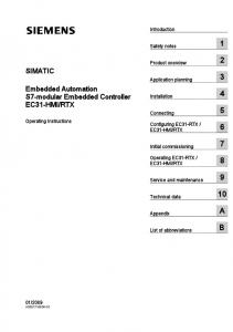
1) Multiplier Speed: AMULET2 includes a 4-bits-percycle multiplier [30] that uses data-dependent early termination. The multiplier cycle time (measured by varying the operand values) is around 6.5 ns, demonstrating the merits of allowing different functions to operate at different speeds. (The main execution pipeline cycles in about 25 ns.) A multiplier constrained to operate at the same cycle rate as the execution pipeline, such as a multiplier in a clocked processor, would require four times as many Booth’s encoders and carry-save adders to deliver the same performance. This illustrates the fact that, under certain circumstances, asynchronous design can save hardware cost. 2) Low-Voltage Operation: The processor appears to tolerate supply voltage variations well. The whole board operates between 2.5 and 4 V, but failures of other components stop the board operating below 2.5 V. In tests which do not involve the other components the chip appears fully functional down to 2 V, at which point the I/O’s stop working. The core appears to continue operating down to 1.1 V, though this can only be surmised by taking it down from and back up to 2 V, since below 2 V the I/O failures prevent external observations from being made. The performance and power-efficiency scale with voltage according to the standard formulas [14]. 3) EMC: The radio-frequency emission from an AMULET2e test card was measured according to the EN 55022 standard in an industrial test facility. The distance between the antenna and the test card was 3 m. The AMULET2e processor was tested running the Dhrystone 2.1 benchmark from external memory, using a nonswitching power supply with 30-cm long supply wires. No particular EMC measures were taken in the design of the PCB, although the UART with its baud rate oscillator was removed for the test. An ARM60 PIE board running at 20 MHz was measured under the same conditions. Fig. 12 shows a logarithmic plot of the field strength (in dBmV/m) against frequency from 30 MHz to 1 GHz in steps of 60 kHz. The horizontal, stepped line shows the EN 55022 limit. The AMULET2e test card emissions are significantly lower than those from the clocked ARM board at all frequencies. The spectrum displays peak field strengths on harmonics of 26.247 MHz, reflecting the average periodicity of the software, but these peaks are much less pronounced than those in the clocked system. 4) Power Breakdown: The AMULET2e chip has separate power supply pins for the core logic and pad ring, allowing the core power dissipation to be measured accurately. In addition, the PowerMill tool (from EPIC Design Technology, Inc.) has been used to obtain an internal breakdown of the core power. The results are summarized in Table 2. It might be expected that the power efficiency (measured as MIPS/W) of the AMULET2 core would be independent of the memory system, since the core does the same work in all cases. However, the nondeterminacy of the instruction prefetch mechanism and the transparency of micropipeline structures mean that there is a dependency as can be seen from these results. 252
(a)
(b) Fig. 12. AMULET2e test card EMC measurements: AMULET2e evaluation board and (b) ARM60 “PIE” board.
(a)
Table 2 AMULET2e Power Breakdown
The on-chip RAM on AMULET2e is very power efficient, using less energy to complete an access than it costs to prepare to go off chip (and off-chip accesses also use pad driver and off-chip memory device power in addition to the on-chip logic). Configuring the on-chip memory as a cache reduces its power-efficiency, as would be expected since the cache requires a CAM tag lookup in addition to the RAM access. B. Benefits of Architectural Features The various architectural features described in Section III were justified on the grounds of their contribution to performance, power-efficiency, or both. It is interesting, therefore, to see what effect they have on the prototype silicon. This is particularly straightforward as they can all be enabled and disabled under software control. A summary of the measurements taken on the test card is given in Table 3. All the measurements were taken running the Dhrystone 2.1 synthetic benchmark program, with the program either resident in the internal memory, cached from the external memory or executed directly from the external memory. The external memory is 80-ns 32-bit static RAM and the PROCEEDINGS OF THE IEEE, VOL. 87, NO. 2, FEBRUARY 1999
Table 3 Architecture Feature Results
power figures are for the AMULET2e core logic including the cache/RAM but excluding the I/O pads. The last line in Table 3 shows the performance benefits of turning all the architectural features on together. 1) LRR’s and LLV’s: The mechanisms used on AMULET2 to perform forwarding were the outcome of considerable development effort, and their contribution to the performance of the device cannot be described as anything other than disappointing. The LRR contributes about twice the benefit of the LLV, but even taken together the net result is meagre. This clearly demands some explanation. The AMULET2 forwarding mechanisms exist to reduce the time an instruction waits for a stalled register read to be resolved. If an instruction does not stall—because the register bank is fully updated by the time it attempts the read—there is no added benefit from forwarding. This can occur when some other pipeline stage limits the instruction issue rate to below that required by the execution stage to complete register write back. For example, external memory in the test card is slow (relative to the processor cycle time) so when it is used as the source of instructions each instruction races through the processor before its successor has been fetched; hence there is no performance gain from enabling the forwarding paths. As the instruction source gets faster gains do appear: the cache system demonstrates a (very) small gain from forwarding, and using the internal RAM (which is faster than the cache) a little more. Unfortunately—as a consequence of limited development resources—even the internal RAM subsystem cycles more slowly than the register read and execute stages and so much of the benefit of pipelining within the processor is lost. Therefore, our conclusion is that the forwarding mechanisms on AMULET2 are capable of delivering more performance benefit than the rest of the AMULET2e system can expose. From simulation results we expect that the AMULET2 execution pipe cycles in 20 ns but the rest of the chip can only sustain an average of around 25 ns. With a faster decode stage, address interface, and memory we would expect considerably more benefit from the forwarding paths in the existing execution pipeline. The next question that must be answered is why was this result not evident during simulation? The answer lies in the critical dependency of the effectiveness of the forwarding mechanisms on the detailed timing of all parts of the chip. Early high-level simulations that were used to FURBER et al.: AMULET2e: AN ASYNCHRONOUS EMBEDDED CONTROLLER
define the architecture were based upon approximate timing estimates. Accurate timings only became available during postlayout simulation using “TimeMill,” by which time the architecture was frozen. It is interesting to observe that in a synchronous implementation the execution path would have been slowed to the memory speed and thus the relative gain (although not the absolute speed) provided by these mechanisms would be more pronounced. The asynchronous design has automatically exploited the faster processing pipeline and any forwarding benefits have been masked. The consequent “waste” of development time could be turned into a case against asynchronous design. However, with its greater freedom to adapt to its working environment it is quite possible that other benefits have accrued. An inevitable conclusion is that it is hard to optimize an asynchronous architecture, especially early in the design process. 2) BTC: The BTC caches 20 branch targets, a number that was chosen on the basis of extensive simulation of a range of applications. Unfortunately, it became clear during those simulations that Dhrystone, the benchmark program used for most our other measurements, has very unusual branch characteristics—it is basically a single large loop with over 20 branches in it, many of which are taken atypically infrequently. This would suggest a BTC of at least 27 entries is needed to optimize Dhrystone performance. We resisted the temptation to optimize the architecture for this synthetic benchmark. Whereas the BTC gives a performance improvement of over 10% on typical programs, it delivers only 7% on Dhrystone. The power efficiency of the core drops by 5% when the BTC is turned on without the power-saving feature described in Section III-C, though the overall system power efficiency rises by 4% when the code is being executed from external memory due to the reduction in wasted instruction fetches. When the power-saving feature is enabled the power-efficiency loss is eliminated, showing that this feature saves around 5% of the total core power dissipation with the BTC enabled. The BTC therefore performs largely as expected and makes a useful contribution to system performance and power efficiency, and the power-saving optimization in the design of the BTC completely eliminates the efficiency penalty the BTC would otherwise incur in the core power. 3) “Halt”: When AMULET2e enters an idle loop without the “Halt” function enabled it consumes between 66 mW and 162 mW depending on how fast the memory system allows the processor to access instructions. With the “Halt” function enabled the power drops to under 0.1 mW if the 32-KHz oscillator is running (and 3 W if it is not). The “Halt” feature therefore delivers a three to four orders of magnitude power saving during idle periods, automatically, and in a way which works with much existing code (including the “Demon” ROM code used in these tests). In many systems, when the processor halts the external system power will also drop to very low levels. The power consumption of the test card is dominated by a single LED when the processor is halted. 253
A clocked system can approach this idling efficiency, but only with considerable effort. The clock must be gated off to all parts of the system that consume significant dynamic power, but in a way that leaves interrupts enabled, and an interrupt must gate the clock back on. Often powermanagement software is used to detect idle periods and to step the power consumption down through a progressive series of stages, reducing clock frequencies and gating out particular parts of the system. Power-management software consumes power itself when running. For very low consumption the oscillators and phase-locked loops (PLL’s) must also be turned off. Stopped oscillators and PLL’s take considerable time to stabilize when they are turned back on, compromising response time when an interrupt occurs. Overall, power optimization in a clocked system is a complex matter involving many tradeoffs. In an application with a significant proportion of idle time, AMULET2e should display remarkable power efficiency with very little effort on the part of the designer. At first sight it might appear that having only two states (maximum performance or halted) is not as flexible as being able to step a clock down through lower frequencies. However, lowering a clock frequency does not, of itself, improve power efficiency. It takes the same energy to perform a given calculation in half the time and to halt for the remaining time as it does to perform the calculation at half the clock rate for the whole time. The only way a lower clock rate can improve power-efficiency is if there is a corresponding reduction in the supply voltage, which is rarely used in practice and can equally (and more easily, as there is no clock to adjust) be applied to an asynchronous system. An additional benefit of the halted state of AMULET2e is that, by stopping all activity, it also removes all sources of electromagnetic interference. Although tests show that AMULET2e has good EMC properties when running under maximum load, these can be further improved by halting the processor when “radio silence” is required. There is no high-speed clock oscillator continuing to generate interference, and maximum performance is available instantly after an interrupt. This technique has potential benefits in many modern time-division multiplexed digital radio communication systems, where in weak signal areas the processor could be shut down during the time slot used to receive each packet.
C. Costs of Architectural Features The last result and last loaded value registers are relatively low-cost features when measured by their requirements for silicon area. They add considerable complexity to the processor’s control logic, however, and therefore they have significant design cost. The BTC has a higher area cost, adding around 15% to the length of the processor core data path. This cost is proportional to the number of branches cached, so a direct cost/performance tradeoff is possible. The halt feature has very low cost, requiring only a handful of gates to be added to the processor control logic. 254
VIII. CONCLUSIONS AMULET2e is a highly usable asynchronous embedded system chip. Its performance and power efficiency are competitive with the industry-leading clocked ARM designs, and in an idle loop its power reduces below that achievable in a clocked design without stopping the clock (whereafter the clocked chip takes considerable time to resume full performance). Its EMC properties are also very attractive, displaying a lower overall emission level and much less severe harmonic peaks than similar clocked circuits. Although in its current form AMULET2e has a minor logic fault and could not be tested economically in volume production, both of these issues could be remedied with a little design effort to deliver a highly effective, fully asynchronous controller for small embedded systems. AMULET2e incorporates several new architectural features and the means to evaluate them (the LRR, LLV, BTC, and abort handling can all be turned on or off independently). As such it contributes to the growing pool of architectural knowledge which must expand considerably further before asynchronous designers can compete with synchronous designers on equal terms. However, seeing is believing, and the reactions of the systems designers who have seen AMULET2e since prototypes first ran have been very favorable. Several prototype applications for the chip are presently under development. We sense that the barriers to the commercial exploitation of asynchronous design are beginning to fall. ACKNOWLEDGMENT The chip in this paper was designed using EDA tools from Compass Design Automation, with accurate simulation using TimeMill from EPIC Design Technology, Inc. being vital to the final verification of the design. PowerMill, also from EPIC, was used after fabrication for the power breakdown analysis. The authors are also grateful for the many helpful comments and suggestions for improvements made by the anonymous reviewers of the paper as first submitted. REFERENCES [1] A. J. Martin, S. M. Burns, T. K. Lee, D. Borkovic, and P. J. Hazewindus, “The design of an asynchronous microprocessor,” in Advanced Research in VLSI: Proceedings of the Decennial Caltech Conference on VLSI, C. Seitz, Ed. Cambridge, MA: MIT Press, 1989, pp. 351–373. [2] A. J. Martin, A. Lines, R. Manohar, M. Nystrom, P. Penzes, R. Southworth, U. Cummings, and T. K. Lee, “The design of an asynchronous MIPS R3000 microprocessor,” in Proc. 17th Conf. Advanced Research in VLSI, 1997, pp. 164–181. [3] T. Nanya, Y. Ueno, H. Kagotani, M. Kuwako, and A. Takamjura, “TITAC: Design of a quasidelay-insensitive microprocessor,” IEEE Design Test Comput., vol. 11, pp. 50–63, Feb. 1994. [4] A. Takamura, M. Kuwako, M. Imai, T. Fujii, M. Ozawa, I. Fukasaku, Y. Ueno, and T. Nanya, “TITAC-2: An asynchronous 32-bit microprocessor based on scalable-delay insensitive model,” in Proc. ICCD’97, pp. 288–294. [5] H. van Gageldonk, K. van Berkel, and A. Peeters, “An asynchronous low-power 80C51 microcontroller,” in Proc. 4th Int. PROCEEDINGS OF THE IEEE, VOL. 87, NO. 2, FEBRUARY 1999
[6] [7]
[8] [9]
[10]
[11]
[12] [13]
[14] [15] [16]
[17]
[18] [19] [20]
[21] [22]
[23] [24] [25] [26] [27] [28] [29]
Symp. Advanced Research in Asynchronous Circuits and Systems (Async’98), pp. 96–107. R. F. Sproull, I. E. Sutherland, and C. E. Molnar, “Counterflow pipeline processor architecture,” IEEE Design Test Comput., vol. 11, pp. 48–59, Mar. 1994. W. F. Richardson and E. Brunvand, “Architectural considerations for a self-timed decoupled processor,” Inst. Elect. Eng. Proc. Computers and Digital Techniques, vol. 143, no. 5, pp. 251–257, Sept. 1996. S. Moore, P. Robinson, and S. Wilcox, “Rotary pipeline processors,” Inst. Elect. Eng. Proc. Computers and Digital Techniques, Sept. 1996, vol. 143, no. 5, pp. 259–265. C. J. Elston, D. B. Christianson, P. A. Findlay, and G. B. Steven, “Hades—Toward the design of an asynchronous superscalar processor,” in Proc. 2nd Working Conf. Asynchronous Design Methodologies, 1995, pp. 200–209. K. Christensen, P. Jensen, P. Korger, and J. Sparso, “The design of an asynchronous TinyRISC TR4101 microprocessor core,” in Proc. 4th Int. Symp. Advanced Research in Asynchronous Circuits and Systems (Async’98), pp. 108–119. M. Renaudin, P. Vivet, and F. Robin, “ASPRO-216: A standardcell Q.D.I. 16-bit RISC asynchronous microprocessor,” in Proc. 4th Int. Symp. Advanced Research in Asynchronous Circuits and Systems (Async’98), pp. 22–31. N. C. Paver, “The design and implementation of an asynchronous microprocessor,” Ph.D dissertation, Dep. Comput. Sci., Univ. Manchester, U.K., June 1994. J. V. Woods, P. Day, S. B. Furber, J. D. Garside, N. C. Paver, and S. Temple, “AMULET1: An asynchronous ARM microprocessor,” IEEE Trans. Comput., vol. 46, pp. 385–398, Apr. 1997. S. B. Furber, ARM System Architecture. Reading, MA: Addison-Wesley, 1996. I. E. Sutherland, “Micropipelines,” Commun. ACM, vol. 32, no. 6, pp. 720–738, Jan. 1989. S. B. Furber, J. D. Garside, S. Temple, J. Liu, P. Day, and N. C. Paver, “AMULET2e: An asynchronous embedded controller,” in Proc. 3rd Int. Symp. Advanced Research in Asynchronous Circuits and Systems (Async’97), pp. 290–299. S. B. Furber, P. Day, J. D. Garside, N. C. Paver, and J. V. Woods, “A micropipelined ARM,” in Proc. IFIP TC 10/WG 10.5 Int. Conf. Very Large Scale Integration (VLSI’93), T. Yanagawa and P. A. Ivey, Eds., North Holland, 1993, pp. 211–220. , “AMULET1: A micropipelined ARM,” in Proc. CompCon’94, pp. 476–485. , “The design and evaluation of an asynchronous microprocessor,” in Proc. ICCD’94, pp. 217–220. S. B. Furber, “Computing without clocks: Micropipelining the ARM processor,” in Asynchronous Digital Circuit Design, G. Birtwistle and A. Davis, Eds. New York: Springer, 1995, pp. 211–262. N. C. Paver, P. Day, S. B. Furber, J. D. Garside, and J. V. Woods, “Register locking in an asynchronous microprocessor,” in Proc. ICCD’92, pp. 351–355. J. D. Garside, “A CMOS VLSI implementation of an asynchronous ALU,” in Asynchronous Design Methodologies, S. B. Furber and M. D. Edwards, Eds. Amsterdam, The Netherlands: North Holland, 1993, pp. 181–192. S. B. Furber and P. Day, “Four-phase micropipeline latch control circuits,” IEEE Trans. VLSI Syst., vol. 4, pp. 247–253, June 1996. D. Morris and R. N. Ibbett, The MU5 Computer System. New York: Macmillan, 1979. J. D. Garside, S. Temple, and R. Mehra, “The AMULET2e cache system,” in Proc. 2nd Int. Symp. Advanced Research in Asynchronous Circuits and Systems (Async’96), pp. 208–217. R. Mehra and J. D. Garside, “A cache line fill circuit for a micropipelined asynchronous microprocessor,” TCCA Newsletter, IEEE Computer Society, Oct. 1995. AMULET2e data sheet, Dept. of Computer Science, Univ. Manchester, U.K. [Online]. Available WWW: http://www.cs.man.ac.uk/amulet/AMULET2e_uP.html. M. Kishinevsky, A. Kondratyev, and A. Taubin, Concurrent Hardware. New York: Wiley, 1994. P. Endecott and S. B. Furber, “Modeling and simulation of asynchronous systems using the LARD hardware description language,” in Proc. ESM ’98: (12th Europ. Simulation Multi-
FURBER et al.: AMULET2e: AN ASYNCHRONOUS EMBEDDED CONTROLLER
conf.), pp. 39–43. [30] J. Liu, “The design of an asynchronous multiplier,” M.Sc. thesis, Dep. Comput. Sci., Univ. Manchester, U.K., Oct. 1995.
Stephen B. Furber received the B.A. degree in mathematics in 1974 and the Ph.D. degree in aerodynamics in 1980, both from University of Cambridge, U.K. From 1980 to 1990, he worked in the hardware development group within the R&D Department at Acorn Computers Ltd. and was a Principal Designer of the BBC Microcomputer and the ARM 32-bit RISC microprocessor, each of which earned Acorn Computers a Queen’s Award for Technology. Since moving to the ICL Chair of Computer Engineering at the University of Manchester in 1990, he has established the AMULET research group with interests in asynchronous logic design and power-efficient computing. One result of this work was the AMULET1 microprocessor, which was recognized with a 1995 British Computer Society Award. Prof. Furber is a Fellow of the British Computer Society and a Chartered Engineer.
James D. Garside received the B.Sc. degree in physics in 1983 and the M.Sc. and Ph.D. degrees in computer science in 1984 and 1987, respectively, all from the University of Manchester, U.K. Since then, he has worked as a Computer Design Engineer in parallel processing architectures and as a programmer in the software industry. He was appointed a Lecturer in Computer Science at University of Manchester in 1991. His main research interests are in the development of the AMULET asynchronous microprocessors.
Peter Riocreux received the M.Eng. degree in electronic and electrical engineering in 1993 from University of Leeds, U.K. He is currently working in the AMULET group in the Department of Computer Science at University of Manchester, U.K., investigating low-power design using self-timed techniques, particularly with respect to DSP devices. Mr. Riocreux is supported by U.K. EPSRC Research Grant GR/L27930.
Steven Temple received the B.A. degree in computer science from the University of Cambridge, U.K., in 1980. In 1984, he received the Ph.D. degree following research into local area networking at the University of Cambridge Computer Laboratory. He was then employed as a Research Fellow at the Cambridge Computer Laboratory before spending several years working for computer companies in the Cambridge area. In 1992, he took up a post as a Research Associate in the AMULET group in the Department of Computer Science at University of Manchester, U.K. His current interests include microprocessor system design, asynchronous logic design, and apiculture. 255
Paul Day received the B.Sc. degree in electronics from University of Manchester Institute of Science and Technology (UMIST), Manchester, U.K., in 1982. He received the M.Sc. and Ph.D. degrees in electrical engineering from University of Manchester in 1988 and 1991, respectively. Between 1982 and 1987, he worked in the field of VLSI test and evaluation at both ICL Computers and IBM. In 1990, he joined the Department of Computer Science at University of Manchester as a Researcher. His main research fields were low-power circuit design, asynchronous systems, and microprocessor design. In 1995, he cofounded Cogency Technology, Inc., to exploit the use of asynchronous low-power circuits and self-timed techniques for commercial applications. In 1998, he left Cogency to form 2n Design Ltd., a company providing consultancy services in low-power asynchronous and self-timed design.
Nigel C. Paver received the B.Sc. degree in electronics from University of Manchester Institute of Science and Technology (UMIST), U.K., in 1988 and the M.Sc. and Ph.D. degrees in computer science from the University of Manchester in 1989 and 1995, respectively. From 1990 to 1995 he worked as a Researcher in the AMULET group in the Department of Computer Science at University of Manchester. His main research interests are microprocessor organizations and self-timed system design. In 1995, he left the University of Manchester and cofounded Cogency Technology, Inc., where he is engaged in the exploitation of low-power self-timed circuits and techniques for commercial applications.
Jianwei Liu received the B.Sc. degree in electrical engineering from the Shenyang Institute of Technology, China, in 1984, the M.Sc. degree in electrical engineering from the Harbin Institute of Technology, China, in 1987 and the M.Sc. and Ph.D. degrees in computer sceince from University of Manchester, U.K., in 1995 and 1997, respectively. From 1987 to 1993 he worked at the Northeast LSI/VLSI center in China, after which he became a Visiting Scholar at the Technical University of Denmark. He now works for Cogency Technology, Inc.
256
PROCEEDINGS OF THE IEEE, VOL. 87, NO. 2, FEBRUARY 1999