Behavior Research Methods, Instruments, & Computers 1996,28 (1),83-88
An automated bisection device for assessing attentional neglect in clinical populations FRED H. PREVIC
Brooks Air Force Base, Texas An automated bisection device (ABD)is described that is designed for use in assessing the direction of three-dimensional neglect in various clinical populations. This device features an apparatus containing two base sections and a connecting rod, on which is located a bisection indicator assemblage that can be moved either by hand or by a calibrated motor-drive system. The indicator assemblage is, in tum, connected to a motor-control box with variable speed settings and a digital readout. The ABD can be used to measure bisection estimations along all three linear axes (lateral, vertical, and depth) by providing visual cues alone, tactile cues alone, or a combination of visual and tactile cues.
A large literature has evolved in recent decades concerning the spatial neglect syndrome in clinical populations suffering from various types of brain pathology (see Jeannerod, 1987). One of the most widely used means of determining neglect has been the bisection technique, in which a subject attempts to determine the midpoint of a line or rod oriented in a certain direction. Patients suffering from an attentional neglect of a certain region of space have been shown to bias their midpoint estimations away from the neglected field, in line with other indices ofneglect in that same field. Until recently, the vast majority of research has studied lateral neglect, which gave rise to the term contralateralneglect-the neglect of the hemifield opposite to the damaged hemisphere, usually the right one. However, more recent studies (e.g., Butter, Evans, Kirsch, & Kewman, 1989; Halligan & Marshall, 1991; Mennemeier, Wertman, & Heilman, 1992; Rapcsak, Cimino, & Heilman, 1988; Shelton, Bowers, & Heilman, 1990) have also begun to investigate bisection performance along the vertical and depth (radial) axes. Partly on the basis of the above studies, Previc (1990) argued that the fundamental organization of the higher visual pathways is derived from our functional interactions in our three-dimensional (3-D) environment. In particular, the dorsal portion of the cerebral cortex-including the posterior parietal and superior frontal cortices-is hypothesized to be responsible for attending to and interacting
I wish to thank the following individuals for their support in developing and testing the automated bisection device (ABO): C. Cole, who fabricated the cylindrical screen and support structure for the ABO; R. Garcia, who built the motor-control and display boxes; C. Oakley, who analyzed the results of the preliminary bisection tests using the ABO; R. Persky, who fabricated and assembled the ABO itself; S. Schanding, who performed the preliminary bisection testing using the ABO; A. Schirmer, who made the schematic illustration of the ABO; and D. Townsend, who designed and tested the electronics of the ABO. The views expressed in this paper are those of the author and do not necessarily reflect the views of the United States Air Force or the Department of Defense. Correspondence should be addressed to F. H. Previc, ALlCFTF, 2504 Gillingham Dr., Ste. I, Brooks AFB, TX 78235-5104 (e-mail: previc%
[email protected]).
83
with stimuli in peripersonal (near) space, whereas the ventral portion housing the inferior temporal and frontal regions is believed to be more critically involved in attending to extrapersonal (far) space. Because of the ecological links between near space and the lower visual field and far space and the upper visual field (see Previc, 1990), the dorsal and ventral pathways may also be more critical for processing information from below and above the line ofsight, respectively. The predominant divisioning ofleft and right space to the right and left hemispheres, respectively, completes the 3-D neuropsychological model, although once again there is a possible interaction involving the far and near attentional systems so that the far attentional system may be predominantly biased to the left hemisphere and the near system to the right hemisphere of most humans. The above theoretical perspective has shown the need for a convenient means of assessing attentional neglect along all three cardinal axes, but there are additional reasons why an automated means of testing bisection performance in 3-D space is required. Current procedures typically require subjects to bisect manually lines placed on a page (e.g., Mennemeier et al., 1992; Scarisbrick, Tweedy, & Kuslansky, 1987; Shelton et al., 1990), move a marker along a rod to the latter's center (e.g., Levander, Tegner, & Caneman, 1993; Mennemeier et al., 1992; Shelton et al., 1990), or adjust a pulley to place a marker at a certain location (Bisiach, Geminiani, Berti, & Rusconi, 1990).1 The limitations of such procedures include (I) the distractions created by the examiner's need to inspect the bisection estimate after each trial, which also prolongs the overall interval required for gathering the bisection data; (2) an inability to precisely commence the bisection task to either side and at variable and specific distances from the true midpoint of the line or rod; (3) imprecision in measuring purely tactile (rod) bisections, which can be on the order of 25 mm (Shelton et al., 1990); (4) difficulty in controlling in a precise and reproducible manner the speed of the bisection indicator along the rod during a purely visual bisection task, which may be the only type of bisection procedure motor-impaired individuals may be able to per-
84
PRE VIC
form; and (5) the inability to study visual, tactile, and combined visual-tactile bisection performance using the same apparatus. For these and other reasons, an automated bisection device was designed and tested to determine its utility as a standardized apparatus in assessing the direction and magnitude of neglect in various clinical settings and populations.
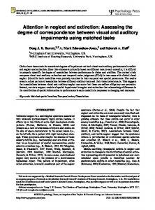
Apparatus The ABD is a platform containing two base sections and a square connecting rod that includes a calibrated scale, a linear potentiometer, and a positionable bisection indicator assemblage that is used to measure the subject's bisection estimate. Photographic and schematic illustrations of this device are shown in Figures 1 and 2. The ABD also includes a variable-stepping motor and control unit (DlGIPLAN Type PK2, Parker Hannifin Corp., Rohnert Park, CA) that drives the indicator assemblage by means of a six-speed control unit and a digital panel meter (PM-350, Non-Linear Systems, San Diego, CA) that shows the instantaneous position of the bisection indicator (Figure 3). The fabrication and assembly of the ABD were accomplished by members of the Operations and Support Directorate of the Armstrong Laboratory at Brooks Air Force Base (principally R. Persky and D. Townsend). The ABD is made of anodized (to appear black) lightweight aluminum and has a total weight of 6.14 kg. Its
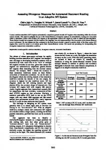
other physical dimensions are presented in Figure 2. The base chamber at one end of the platform houses the stepping motor used to drive the bisection indicator assemblage and is placed on the support surface in vertical bisection measurements. The base section at the other end is an equivalently sized empty chamber that can be removed by means of six Allen screws and replaced by a stand that permits the entire connecting rod to be viewed when it is oriented in the same direction as the subject's visual axisthat is, when the ABD is used for bisection measurement along the depth axis (see left inset of Figure 2). (The inclusion of the empty base chamber-which, like the opposite one housing the stepping motor, is partially soundproofed using foam sheets-is intended merely to create symmetry in the overall shape of the ABD during vertical and horizontal testing.) Between the base chambers is a square connecting rod (actually a square tube), the inner portion of which has a length of 30 cm (a standard length used in rod-bisection experiments). On one of the four sides of the rod is a calibrated scale that ranges from +15 to - 15 em in 2-mm increments from the midpoint of the ABO, (In the standard configuration, negative values reflect bisection judgments to the right, below, and farther away than the true midpoint of the rod.) A second side contains a rotating screw drive along which the indicator assemblage moves, while a third side contains a 5-kohm linear potentiometer (PTL-300,
Figure 1. Two views ofthe automated bisection device (ABO): the bisection indicator and end stops, which face the subject during testing (left); and a view ofthe calibrated scale, the indicator assemblage with its half-nut clasp lever, and the screw-drive rail (right).
BISECTION DEVICE
85
AUTOMATED BISECTION DEVICE
r
---(,r-
84.1
-45.7 _ _
~~ ~'
2.5
SIDE 1
!
@ e
0
0
SIDE 2
Figure 2. A schematic drawing of the automated bisection device (ABO), showing its measurements in centimeters. The inset figures show the ABO when the second base chamber is replaced by a smaller stand in the depth bisection testing (left inset) and two opposite-side enlarged views ofthe bisection indicator assemblage that is moved along the screw-drive rail during testing (right inset). The arrows in the right inset show how the clasp lever is released to allow the indicator assemblage to move freely along the rail.
Novotechnik, Marlboro, MA) that is activated by sliding contacts on the movable indicator assemblage and whose output is sent to the digital panel meter. The I-shaped bisection marker located on the movable indicator assemblage that the subject aligns with his/her midpoint estimation lies above the final side of the square rod (see right inset of Figure 2), which faces the subject; this side also contains two end stops separated by 30 em, which are aligned with the ends of the calibrated scale and rotating screw drives on other sides of the rod. When properly positioned, only the side with the indicator assemblage and end stops can be seen by the subject. In the manual mode, the subject moves the indicator assemblage by depressing a clasp lever on a brass half nut, which allows the indicator assemblage to move freely along the screw-drive rail. In the automated mode, the indicator assemblage is driven by inputs from the stepping motor and its motor-control unit. Although the stepping motor can produce a variable range of speeds, the black motor-control box (Figure 3) has six speed settings-fast, medium, and slow speeds, with high and low versions of each-and a bidirectional capability. Nominally, the different speed settings range from 1.25 em/sec (fast-high)
to 0.1 em/sec (slow-low), although these values can be altered by adjusting the settings on the six potentiometers located inside the motor-control unit. A reset button (R) is also available whenever a fault situation arises in the control of the stepping motor. The display unit (Figure 3) is a black box that shows a digital readout of the position of the indicator assemblage (in millimeters) and has three settings: an "operate" setting and two power settings (±1.5). For normal operation and calibration, the "operate" setting is used. To calibrate properly (1) the adjustable ( - ) knob is turned so that the digital display reads "-150" when the indicator assemblage is positioned at the "low" end ofthe ABD, and (2) the (+) knob is adjusted so that the digital display reads "+ 150" when the indicator assemblage is positioned at the "high" end ofthe ABD. The display should then be linear over the entire movement range of the indicator assemblage.
Measuring 3-D Bisection Performance Using the ABD In measuring bisection performance using the ABD, the subject should ideally be placed in a darkened room to eliminate any asymmetries created by the room or the ABD.
86
PREVIC
Figure 3. A view ofthe motor-control unit with its six settings-fast (F), medium (M), and slow (5), with high (H), low (L), and off (0) settings for each-and the digital readout display with its three settings ("OPERATE," "-1.5," and "+1.5") and two adjustable calibration knobs.
Such a procedure requires that phosphorescent tape be placed on each of the two end stops and on the bisection marker. Alternatively, the subject could view the basically symmetrical ABD in a dimly lit room against a cylindrical background screen (Figure 4), which minimizes (but does not totally eliminate) any asymmetries in the visual environment. Because the stepping motor housed at one end ofthe ABD produces detectable noise, the use ofsubject earmuffs is further recommended. Subjects should additionally be positioned in a chinrest to ensure proper head positioning and stability (Figure 4). The chinrest should be placed so that the subject's eyes are level with the midpoint ofthe ABD in the vertical position. During horizontal and depth bisection testing, a support structure is required to place the ABD's connecting rod at the same height as the midpoint of the ABD in the vertical position. The chinrest must be slightly elevated in testing depth bisection estimates, however, so that the entire extent of the bisection rod (including the two end stops) is visible to subjects as they gaze slightly downward at the ABD. To ensure that the ABD remains immobile while subjects move the indicator assemblage manually, velcro strips can be placed both on the support surfaces and on the ABO, To further ensure that bisection judgments along
the lateral axis are not spuriously altered by which hand is used to move the indicator assemblage, subjects should be required to move the assemblage by means of the clasp lever using both hands.
Bisection Estimates From Normal Subjects Using the ABD In a preliminary study, it proved possible to obtain bisection estimates from a total of 18 subjects along all three axes under three different conditions (visual, tactile, and visual-tactile) in a single 30-45-min session. The ABD was under completely automated control in the visual condition, with the bisection indicator assemblage traveling at an initial velocity of 1.25 ern/sec. The subject was instructed to tell the examiner to stop as the perceived midpoint of the square rod was reached, with one or two further adjustments usually required using a slower speed setting. In the other two conditions, the subjects moved the indicator assemblage themselves to the perceived midpoint. (In the tactile condition, in which occluding goggles were worn, subjects could use their hands to lightly run along the connecting rod and its two end stops but were not permitted to use their fingers as "measuring sticks" per se.) Six trials were performed in each condition, with half of them
BISECTION DEVICE
87
Figure 4. A view of a subject using the ABD during vertical bisection testing, showing the subject holding the clasp lever in front of the background cylindrical screen.
starting from preset positions on one side of the ABD (at +5, +10, and + 15 em) and the other half starting from the other side of the ABD (at -5, -10, and -15 em), Subjects were told to make their bisection judgments as quickly and as accurately as possible and were allowed approximately 30 sec to make each one. The above procedures were completely counterbalanced across conditions and axes except in one respect. To save time, subjects were tested on the three axes in one of the following two orders: depth, horizontal, and vertical; or, vertical, horizontal, and depth. (The linkage ofdepth and horizontal bisection testing is efficient because both require the additional support structure, whereas the linkage of vertical and horizontal testing is efficient because both use the full base chamber rather than the smaller stand at the end opposite to the section housing the stepping motor.) The preliminary results indicated that normal subjects bisect the distance between the two end stops very close
to the true midpoint along all three axes, but especially along the horizontal and vertical ones. Along the horizontal axis, the means were -0.19, -0.02, and -0.22 em (all to the right of the true midpoint) for the visual, tactile, and combined visual-tactile conditions, respectively. Along the vertical axis, the means were -0.03, +0.09, and +0.09 em for the visual, tactile, and combined visualtactile conditions, respectively. Finally, the means in the same three conditions along the depth axis were -1.43, -0.58, and -0.74 cm (all farther than the true midpoint). Only the midpoint estimates in the depth condition were shown to differ significantly from the true midpoint (zero) at a probability level of .05 or higher [t(17) = 4.42,3.75, and 3.76, for the visual, tactile, and visual-tactile conditions, respectively]. The failure to find significant biases along the vertical and horizontal axes is in general agreement with the small and/or inconsistent results obtained in many previous bi-
88
PRE VIC
section studies (see Levander et aI., 1993; Scarisbrick et aI., 1987; Shelton et al., 1990), whereas the bisection bias toward more distant space along the depth axis is consistent with previous visual (but not necessarily tactile) bisection findings (Geldmacher & Heilman, 1994; Shelton et aI., 1990).
Future Clinical Applications The ABD is primarily designed to be used with clinical populations that may suffer from a disturbance of attention along one or more ofthe three principal axes. As noted, many studies have suggested that disorders of3-D neglect may follow parietal and temporal cortical damage, and it is likely that neglect may follow frontal damage as well. Studies of3-D neglect using the ABD are currently being planned, in conjunction with otherneuropsychological tests, for patients suffering from various types ofcortical lesions as well as specific damage to other parts of the brain. Disturbances of3-D attention may also occur in response to neurochemical imbalances and more generalized brain disorders. For example, schizophrenics are believed to have an exaggerated emphasis on extrapersonal space at the expense of peripersonal space (Previc, 1993), and this may also be true ofrelated disorders that are accompanied by dopaminergic disinhibition, such as Huntington's disease. In contrast, Parkinsonian patients tend to be especially impaired in making upward saccades (Corin, Elizan, & Bender, 1972), which could reflect a deficit of dopaminergically mediated extrapersonal (upward) attention. Likewise, patients suffering from severe temporal lobe damage in Alzheimer's disease may exhibit disturbances in their extrapersonal attentional system, which could explain their tendencies to draw large clocks (Rouleau, Salmon, Butters, Kennedy, & McGuire, 1992) that frequently manifest disturbances in the upper visual field (e.g., Henderson, Mack, & Williams, 1989), as well as their characteristic loss of topographic orientation ("wandering" behavior) (Henderson et aI., 1989). Thus, the ABD is a device that hopefully will be used to generate new and easily reproducible findings that will considerably expand our knowledge of the neuropsychology of3-D attention and neglect in humans.
REFERENCES BISIACH, E., GEMINIANI, G., BERTI, A., & RUSCONI, M. L. (1990). Perceptual and premotor factors of unilateral neglect Neurology, 40, 1278-1281.
BUTTER, C. M., EVANS, 1., KIRSCH, N., & KEWMAN, D. (1989). Altitudinal neglect following traumatic brain mjury: A case report. Cortex, 25,135-146.
CORIN, M. S., ELIZAN, T. S., & BENDER, M. B. (1972). Oculomotor function in patients with Parkmson's disease. Journal 0/ the Neurological Sciences, 15,251-265.
GELDMACHER, D. S., & HEILMAN, K. M. (1994). Visual field mfluence on radial line bisection. Brain & Cognition, 26, 65- 72. HALLIGAN, P. W., & MARSHALL, J. C. (199 J). Left neglect for near but not far space in man. Nature, 350, 498-500. HENDERSON, V. w., MACK, w., & WILLIAMS, B. W. (1989). Spatial disonentation in Alzheimer's disease, Archives ofNeurology, 46, 391-394. JEANNEROD, M. (ED.) (1987). Neurophysiological and neuropsychological aspects ofspatial neglect. Amsterdam: Elsevier, North-Holland. LEVANDER, M., TEGNER, R., & CANEMAN, G. (1993). Tactile lmebisection in normal subjects. Perceptual & Motor Skills, 76, 83 J-836. MENNEMEIER, M., WERTMAN, E., & HEILMAN, K. (1992). Neglect of near peripersonal space. Evidence for multidirectional attentional systems in humans. Brain, 115,37-50. PREVIC, F. H. (1990). Functional specialization m the lowerand upper VIsual fields in humans: Its ecological origms and neurophysiological implications. Behavioral & Brain Sciences, 13, 519-542. PREVIC, F. H. (1993). A "neuropsychology of schizophrenia" without VISIOn. Behavioral & Brain Sciences, 16,207-208. RAPCSAK, S. Z., CIMINO, C. R., & HEILMAN, K. M. (1988). Altitudmal neglect. Neurology, 38, 277-281. ROULEAU, I., SALMON, D. P.,BUTTERS, N., KENNEDY, C., & MCGUIRE, K. (1992). Quantitative and qualitative analyses of clock drawmgs In Alzheimer's and Huntington's disease. Brain & Cognition, 18,70-87. SCARISBRICK, D. J., lWEEDY, J. R., & KUSLANSKY, G. (1987). Hand preference and performance effects on line bisection. Neuropsychologia, 25,695-699
SHELTON, P. A., BOWERS, D., & HEILMAN, K. M. (1990). Penpersonal and vertical neglect Brain, 113,191-205.
NOTE I. In one of their experiments invesnganng purely visual brsection, Mennemeier et al. (1992) described a serruautomated apparatus involvmg a mechanical stylus moving at a constant rate, but they gave no other details of this device.
(Manuscript received November 4, 1994; revision accepted for pubhcanon March J 7, 1995.)