order to test the system, a knee-ankle-foot orthosis has been instrumented for gait control and monitoring of biomechan- ical and comfort data during daily use by ...
AN AUTONOMOUS CONTROL AND MONITORING SYSTEM FOR A LOWER LIMB ORTHOSIS : THE GAIT PROJECT CASE J. C. Moreno, F. J. Brunetti, J.L. Pons Instituto de Autom´atica Industrial, CSIC (Spain) ABSTRACT A wearable control and monitoring system has been developed for a novel active orthotic device. The development covers the need of an autonomous tool for gait analysis during normal use of the orthotic device. The system has two basic components: the Base Unit and the Ambulatory Unit. The units communicate by means of a Bluetooth link. In order to test the system, a knee-ankle-foot orthosis has been instrumented for gait control and monitoring of biomechanical and comfort data during daily use by patients with muscular deficiencies. This paper describes the system developed, outlines its performance and presents measurements recorded while performing different activities. 1. INTRODUCTION Lower leg disorders affecting human mobility have been commonly treated by means of orthoses to partially compensate functional loss. These devices are used to modify structural or functional characteristics of the neuromusculoskeletal system. Knee-Ankle-Orthoses (KAFOs) are prescribed for subjects with orthopedic and neurological diseases mainly to provide stability to the joint when muscles are weak. Commercially available KAFOs guaranty security while keeping joints locked but result in non-cosmetic and high energy demanding patterns. Other systems adapt more dynamically during gait, controlling the knee joint during the swing phase triggering a mechanism based on ankle range of motion (Utx Swing Orthosis) or managing the loading response by springs (Becker). This evolution sets the basis for research efforts in enhancing autonomy. Autonomy of a system for use by a disabled is a crucial goal in mobility restoration by artificial means; portable technologies have been proposed to assist human impaired motor control [1]. Gait control strategies to recover or improve mobility with KAFOs can be classified with regard to the type of control actions on joints, segments or muscles: The work presented in this paper has been carried out with the financial support from the Commission of the European Union, IST programme under contract no. IST-2001-37751, ”GAIT – Intelligent Knee and Ankle Orthosis for biomechanical evaluation and functional compensation of joint disorders”
locking/releasing, braking, damping or powering. Most explored technique to control gait, functional electrical stimulation (FES) has been reviewed [2]. Hybrid systems, combining FES with orthoses to provide ambulation to paraplegic patients have been explored widely [3]. Discomfort related to stimulation is the major problem of this technique and results are not evidence of a good control of body motion neither energy expenditure reduction. Engineering attempts on adaptation of brakes [4] and clutches [5] to knee braces have been reported. Actuators designed for robotic systems, have been proposed to correct drop foot [6] controlled by external computers. Systems for autonomous use have been designed on the basis of microcontroller and microprocessor technologies for automatic correction of gait, mostly for application of implantable stimulation. Regarding sensors for gait control, foot switches have been used initially for synchronization of stimulation signals [7]. Problems associated with the switches reliability have guided to approaches considering other sensors as goniometers, tilt sensors, and accelerometers [8] have been proposed for detection of events to control FES. The gait monitoring systems give clinician useful information to calibrate and optimize prescription of rehablitation equipment. This tool would also help therapists in training patients in the use of new orthotic devices. Commonly, calibration of KAFOs is trail and error procedure based on clinician experience. Electronic for orthotic devices were developed [9], [4], [10] but all of these works were oriented to control. There also exists gait monitoring devices like step counters. The purpose of this device is to help to measure physical activity under free-living conditions. By now there are no system that measure gait biomechanical parameters under normal life. Moreover, a lack of information about performance during daily activities with orthoses is latent. Biomechanical and clinical evaluation has been always developed in the laboratory context. Activity Monitoring during daily use of an autonomous KAFO would redound in the improvement of the prescription and rehabilitation processes while providing useful information to the involved specialists. For all the above, we propose in this paper a novel au-
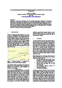
2. CONCEPT The system proposed has two main components: the Base Unit and the Ambulatory Unit. The ambulatory unit is mounted on the orthosis. It controls the orthosis functionalities and records data for future analysis. Its is also capable to communicate with the Base Unit to download recorded data during daily use of the orthosis. The Base Unit is located at the clinic or gait lab. It is a software running in a PC. Both components have tools for gait analysis. Interfacing with user is another topic considered in the system. While the Base unit mostly interacts with clinician, the ambulatory unit does with patient. Interfacing hardware like vibrator motors or audible signals generators can be managed by the ambulatory unit. We can classify system performance in real time and off-line modes. The purpose of real time mode is to show important information to patient or clinician immediately. Knowledge about the state of a biomechanical variable might be important for safety purposes. Another real time application can be to display a group of variables on the base unit screen, as a tool for clinicians and specialists. The off-line application are oriented to commit the monitoring objectives of the system. Biomechanical data about the user activity (walking, sitting up/down, standing) during daily use as time of use, are logged in the ambulatory unit in order to be analyzed by clinician or orthopedist. With all these data available and the configuration tool provided by the software, the therapist or orthopedist can adjust the orthosis to the patient and in this way optimize the prescription period. The units exchange information using between the unit using a Bluetooth Module (Bluegiga Wrap Thor). A Wireless Telemetry systems for training prothesis users has been already proposed by Kyberd [11] and Matjacic [12] to avoid problem with cable considering the intrinsic mobility characteristic of limb orthoses/prostheses. Bluetooth provides versatility and mobility to the system. Even the system becomes a mobile gait lab, one of the objectives of the project considering that by this moment, gait analysis is restricted to laboratory environment. The ambulatory unit is a an electronic board with a microcontroller(Atmega128, Atmel Inc.), a SRAM(8 Mbits, BSI Inc.) chip and a Bluetooth module. The board is powered by an rechargeable Lithium Ion battery (CGA-7/102F, 3.7
ORTHOSIS
Actuators
Comm Unit
Ambulatory Unit Sensor Set
Control Unit
tonomous control and monitoring system for a new generation or orthotics and its application on the Gait Project, allowing research and testing of actuators, control algorithms and besides, as a tool for activity monitoring during daily use. The system involves a sensor set instrumentation, control architecture, data storage hardware and wireless communication, all designed to cope with ambulatory monitoring and control objectives.
Base Unit
Fig. 1. System concept. V, 900 mAh, Matsushita Ind. Corp.). The size of the board is 61x49 mm. The Bluetooth module is mounted on a secondary board, which size is 43x32mm. There are 8 ADC channel for the sensors in the orthosis. One of them is shared with the battery level meter. The resolution of each channel is up to 10 bits. The Base unit is a PC running the Gait Project software. The Base unit also needs a Bluetooth module to establish a wireless link with the ambulatory unit.The software of the Base unit has tools for set up the orthosis and analyze downloaded data. A very important design characteristic is the system power source. One of the main objectives of this system is to reach a significant level of autonomy. Many batteries technologies has been lately developed. Nowadays Lithium Ion is the battery technology imposed in market. Mobile devices such as cellular phones or PDAs uses this type of battery. Lithium Ion batteries have a good power density but on the other hand standard sizes are not available, which is an inconvenient when the user want to replace his discharged battery during normal use. 3. METHODS AND MATERIALS In order to test the system functionalities, obtain raw data from the sensor set and evaluate them for recognition algorithms develop in GAIT project, experiments were performed. 3.1. Knee-Ankle-Foot Orthosis A standard single bar Utx Orthosis, with a free knee joint and ankle restricted to +/- 20, was instrumented with a variety of sensors and electronics to collect the following parameters: knee and ankle joints angles, segments (lower leg, upper leg and foot) velocities, foot (heel and toe) contacts and forces supported by the frame. Following sections describe the sensors and Control and Acquisition Unit. 3.2. Sensors The group of sensors providing this information to the control and monitoring system is formed by: 1) Two force sensitive resistors (FSRs), used to measure repetitive contact/non contact of the foot with the switch, 2) two strain gauges
3.3. Control and Acquisition Unit The prototype of Control and Acquisition Unit was used for these trial sessions. It consisted in three boards. The first board is the main one, where the microcontroller and memory chips are located. The second one is the Bluetooth Module board and the last one is the conditioning board with a los pass filter for sensors and a threshold circuit for FSRs is used. Digital port was used to acquire FSRs signals considering that binary information is required from these sensors.
4. SYSTEM PERFORMANCE
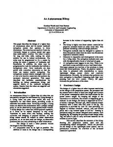
Gyro A/D value (Foot)
Gyro A/D value (Lower bar)
Gyro A/D value (Upper bar)
A health subject wearing the orthosis equipped with the system, performed the following trials during separated sessions: slow and normal walking, dealing stairs and slopes / up and down), sitting down and standing up. For illustration, we present data from two different level walking trials, slow and normal speeds, respectively. Data recorded under the monitoring mode of the system, corresponding to level walking activity are presented. The subject performed all activities moving freely and around a 6m perimeter. The angular velocities signals from three rate gyroscopes are shown in Fig. 1. During walking, the dynamic performance of the gyroscopes shows a good correspondence with segments angular velocities and capture segments dynamics properly. Recorded digital signals from foot switches are also shown in 2.
Foot switches
bridges to detect strains resulting from loading at the lower bar, 3) rate gyroscopes at the lateral aspect of the foot plate, upper bar and lower bar of the orthosis, to measure segments rotation velocities on the sagittal plane, and 4) two precision rotational potentiometers to measure knee and ankle joints angles. The sensor signals were sampled by the Control and Acquisition Unit (CAU) at a sampling rate of 60Hz with a resolution of 8 bits. Flat FSRs (LuSense, 1cm diameter) were placed between KAFOs plate and underneath toe and heel according to specific foot characteristics. FSRs were used as switches providing contact information. Signals from each sensor were driven with a variable threshold circuit, based on a voltage divider, to allow sensors sensibility tuning. Two transducers based on active and passive strain gauges were disposed on the lower lateral bar of the KAFO, approximately 150 mm above from the ankle joint. Each of two force sensors are composed by a full Wheatstone bridge configuration, to compensate for temperature drift and maximize voltage sensibility to strains resulting from moments applied dynamically along and perpendicular to the axis of the orthotic bar. Strain signal conditioning circuit is based on a precision instrumentation amplifier and designed to permit input and output errors compensation and noise filtering. Precision potentiometers (Bourns, 6538) were mounted on the orthotic hinges in order to measure knee and ankle angles; excitation supply is given by a stable low dropout voltage reference, in order to obtain a stable output. Rate gyroscopes (Gyrostar enc-03j) were mounted over each bar of the orthosis, corresponding to each lower leg segment (thigh, shank, foot) oriented in the sagittal plane, perpendicular to the axis of the segment. Rotational velocity of each segment can be obtained from the gyroscopes, which internally sense mechanical deformations, caused by the Coriolis force exerted on a internal oscillating part. Sensor signals are filtered by a band-pass filter circuit (between 0.3-25Hz). Orthotic bars are assumed as single bodies moving together with the body and no relative displacements are present. Relative rotational velocity about joints can be further calculated by subtraction of rotational velocities between the two linked segments, under the assumption of one degree of motion due to orthosis stiffness.
200 100 0
0
2
4
6
8
10
12
0
2
4
6
8
10
12
0
2
4
6
8
10
12
0
2
4
6
8
10
12
200 150 100
200 100 0 1 0 −1 −2
Time [sec]
Fig. 2. Level walking signals from the three gyroscopes mounted on the lateral bar (A/D signals, from top to bottom: upper bar, lower bar and foot plate) and switches over the plate (up: heel, down: toe).
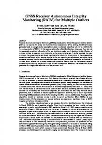
Signals measured during four gait cycles at normal speed, from the force sensor (strain gauges full bridge) mounted on the lower bar and the knee angle sensor are shown in 4. Dynamically, strains on the frontal aspects of the lower bar vary depending on the bending moments resulting from the ground reaction force and resulting forces from the interaction between the structure and the body parts. Angle sensor data corresponds to relative angle between lower and upper orthotic bars, the knee hinge angle. During the stance phase non flexion was present due to kinematical limitations imposed by the ankle angle restriction. No transmitted data was lost during the trial.
Angle sensor A/D value
180
[2] G. M. Lyons, T. Sinkjaer, J. Burridge, and D. J. Wilcox, “A review of portable fes-based neural orthoses for correction of drop foot,” IEEE Transactions on Neural Systemas and Rehabilitation Engineering, vol. 10, no. 4, 2002.
175 170 165 160 155 150 145
0
1
2
3
4
5
6
7
Force sensor A/D value
150
140
[4] M. Goldfarb and W. K. Durfee, “Design of a controlled-brake orthosis for fes-aided gait,” IEEE Transactions on Rehabilitation Engineering, vol. 4, 1996.
130
120
110
[3] G. Baardman and M. J. Ijzerman, Design and Evaluation of a Hybrid Orthosis for People with Paraplegia, University of Twente, 1 edition, 1997.
0
1
2
3
4
5
6
7
Time [sec]
Fig. 3. Level walking signals from angle sensor mounted on the knee hinge (top) and full bridge mounted on the lower bar of the orthosis (bottom). 5. CONCLUSIONS We developed a system to monitor and control activities while using a KAFO. The autonomy of the system has been demonstrated while been able to store continuously data for 24 hours and to communicate in real time with a PC for clinical evaluation. The full duplex communication of the system, allows the adjustment of parameters of the ambulatory control unit from the base unit. Higher sampling frequencies (above 60Hz) might be require in application where detection of higher frequency transients is required. Real time monitoring data received at the base station can be used for assessment of pathologies and improvement of the evaluation and fitting processes of the orthotic device. It can be concluded from the experiments, that this system will perform adequately control strategies based on the sensor set signals. An example of application of the presented system, consists in an intelligent orthosis currently under developed in the frame of the European Project GAIT. The application of this system to control the Gait KAFO is under research and further work will evaluate its performance. 5.1. Acknowledgements The authors would like to thank C. Baten and W. de Vries for their important contributions on experiments. 6. REFERENCES [1] PH. Veltink et al, “A strategy for adaptive tuning of a two-channel preoneal nerve stimulator for dropfoot,” in 7th Annual Conference of the International Functional Electrical Stimulation Society, Ljubljana, 2002.
[5] S. Irby, K. Kaufmaun, R. Wirta, and D. Sutherland, “Optimization and aplication of a wrap-spring clutch to a dynamic knee-ankle-foot orthosis,” IEEE Transactions on Rehabilitation Engineering, vol. 7, no. 2, 1999. [6] J. Blaya and H. Herr, “Adaptive control of a variableimpedance ankle-foot orthosis to assist drop foot gait,” Tech. Rep., Artificial Intelligence Lab and Harvard/MIT Division of Health Sciences and Technology, 2004. [7] P. Strojnik et al., “Treatment of drop foot using and implantable peroneal underknee stimulator,” Scand. J. Rehab. Med., vol. 19, 1987. [8] P. Veltink and H. Franken, “Detection of knee unlock during stance by accelerometry,” IEEE Transactions on Rehabilitation Engineering, vol. 4, no. 4, 1996. [9] S. Gharooni, B. Heller, and M.O. Tokhi, “A new hybrid spring brake orthosis for controlling hip and knee flexion in the swing phase,” IEEE Transactions on Rehabilitation Engineering, vol. 9, no. 1, 2000. [10] S. Irby, “Electromechanical joint control device with wrap spring clutch,” 2002, Patent Number US 65000138 B1. [11] P. J. Kyberd, S. Te Winkel, and A. Poulton, “A wirelles telemetry system for training users of upper limb prostheses,” Prosthetics and Orthotics International, vol. 26, 2002. [12] Z. Matjacic, M. Munih, T. Bajd, and A. Kralj, “Voluntary telemetry control of functional electric stimulators,” Medical Engineering Technologies, vol. 20, no. 1, 1996.