An Efficient I/O Interface Control Block Design. Methodology for Application-Specific MPSoC. Platforms. Myoung-Seo Kim, and Jean-Luc Gaudiot. University of ...
An Efficient I/O Interface Control Block Design Methodology for Application-Specific MPSoC Platforms Myoung-Seo Kim, and Jean-Luc Gaudiot University of California, Irvine, California {myoungseo.kim, gaudiot}@uci.edu
Abstract—In application-specific multiprocessor system-on-achips (MPSoC), the complexity of a general-purpose interface control block which implements input/output (I/O) paths for offchip communication has increased exponentially in recent years. In addition, several inherent issues exist in the design of generalpurpose interface control blocks, since many registers and multiple I/O paths are fixed in the relatively late stages of the design, which consequently reduces verification time of the top level. Also, the role of a general-purpose interface control block, which shares a limited number of pins with various IPs, causes frequent changes in pin assignment. This results in many possible human errors when using a traditional RTL description in designing such blocks. In response to this problem, this paper presents a Design Automation-based approach to improve the efficiency and reliability of the design process. In the case study presented, we succeeded in auto-generating a general-purpose interface control block in typical MPSoC platforms with more than 400 general-purpose interfaces including both input and output, as well as 1,200 PAD pins. Ultimately, we reduced the amount of manual description for the generation of a generalpurpose interface control block by a whopping 98%. Keywords—general-purpose interface control block; design automation; application-specific multiprocessor system-on-a-chip
I. INTRODUCTION As design productivity cannot follow the rapid advance of fabrication technologies, the development of a new design methodology has become necessary. Automating platform integration and verification process is one possible avenue [1, 2]. Several technologies have been proposed so far to solve this issue. Among these approaches, the IP-XACT (IEEE1685) standard [3] which was originally progressed by the SPIRIT consortium [4, 5] defines a way to describe and handle multi-sourced Intellectual Property (IP) components. In addition, it enables the automated design integration and configuration within multi-vendor design flows. For example, commercial schemes of automated design for signal multiplexer (MUX) and PAD blocks have been presented [6, 7]. However, little effort on improving the design productivity of a general-purpose interface control block has been made. Several architectural parameters of such commercial solutions, such as the maximum number of I/O pins [8], PAD
control signals [9], and various address regions, make it difficult to reuse the general-purpose interface control block. This has been provided as a general solution for the automation of design process. As a result, register transfer level (RTL) designers rely on a manual approach to design, which is time-consuming and error-prone in the usually limited timeframe of the design cycle [10]. Moreover, it is difficult to keep consistency among RTL designs when design modifications in the general-purpose interface control block are frequently required. In this paper, we propose an advanced automated scheme for the design of a general-purpose interface control block. The key idea is to process a formalized text through our upgraded auto-generator expressed in the script programming language. Using this approach, designers can automatically generate RTL blocks, thereby reducing possible human errors and design time, while maintaining consistency among the generated outputs. The remainder of this paper is organized as follows. Section 2 introduces the structure of a general-purpose interface control block. Then, detailed structure and functions of the proposed method are introduced in Section 3. Section 4 shows the experimental results and our analysis of the proposed method, followed by some conclusions in Section 5. II. STRUCTURE OF GENERAL-PURPOSE INTERFACE CONTROL BLOCK
An MPSoC contains many IPs and incorporates a generalpurpose interface control block to form a top-level RTL design with a tremendously large number of signal connections. As a result, integrating a general-purpose interface control block with a top-level RTL design is not only time consuming but also vulnerable to human errors. Thus, a design automation-based approach to alleviate the need for such tedious work is necessary. The core architecture of a general-purpose interface control block is already introduced [11]. This architecture has multi-functional port pins organized in several groups with a similar model. Each port can be easily configured by software to meet various system configuration and design requirements.
978-1-4799-4441-5/14/$31.00 ©2014 IEEE
These multi-functional pins need to be properly configured before they can be used. If a multiplexed pin is not used as a dedicated functional pin, this pin should be configured as a generic input or output port. When a pin is configured as an input port by clearing the output enable line and setting the input enable line, the external signals are written to the Input Data Register. Alternatively, if a pin was configured as an output port, the value in the output data register will drive the Generalpurpose Interface. Some pins must be programmed in a special mode such as low-active input, bi-directional, or lowactive bi-directional mode. If an appropriate pin in an input mode is not selected, the default pin value will be set to 0. However, in case of an active-low input, the default pin value will be set to 1. The pin in a bi-directional mode, which can be used in an input or output mode, has an output enable signal directly connected to the output enable signal of the general-purpose interface control block. As for the low-active bi-directional mode, the inverted signal of the output enable is connected to the output enable signal of the general-purpose interface control block. The reuse of a general-purpose interface control block is now considered to be the foundation of MPSoC design [12, 13, 14]. It is the only methodology allowing the design of complex MPSoCs to meet the limited design timeframe, productivity, and quality requirements. However, the challenge of designing a general-purpose interface control block nowadays is how to efficiently employ the reuse methodology. We thus introduce an automated design scheme to overcome such challenge. More specifically, we believe it is possible to significantly reduce both human errors and design time if the parts that frequently change when designing the general-purpose interface control block can be implemented with a formalized text in an automated way.
as another type of bus which includes many other side signals interfacing different IPs and PAD directly. Each signal in the general-purpose interface control block belongs to its own type of bus as defined above. To express all the functions and parameters with respect to connections of the general-purpose interface control block, we devised a formalized description approach. The description of this formalized text which is depicted in the spreadsheet-style input template has proposed [11]. A designer can model RTL blocks by using control properties in the proposed formalized text. The fundamental auto-generator [11] will then automatically convert the proposed formalized text into corresponding logics. In particular, the active-low input (LI) mode indicates that the initial value of input data will be set to 0. However, the initial value of the input data will normally set to 1 when the lowactive input mode is activated. Also, the bidirectional mode directly controls the output enable signal of the general-purpose interface control block. However, the inverted output enable signal is connected to the output enable signal of the general-purpose interface control block when the active-low bidirectional (LB) mode is activated. B. Specific Functional Requirement In addition to the basic I/O function of the general-purpose interface control block, our proposed block has special functions that can efficiently control an interface of an application-specific MPSoC platform. This block includes special registers used to support functions shown in the five bottom rows of Fig. 1. The base address of each register group is added to the memory information of an application-specific MPSoC platform.
III. SPECIFICATION WITH FORMALIZED TEXT In this section, we define the types of special registers according to the functional requirements of the generalpurpose interface control block and propose a formalized text approach to unify various architectures for the generalpurpose interface control block. Various fundamental requirements which are essential to implement both functionalities and configurable parameters of the general-purpose interface control block have expressed in [11]. To express all these requirements compactly, we need to develop a formalized text approach. A. Formalized Text Our proposed formalized text defines types of interface connections and presents an effective way to map definitions onto physical ports. The signal interface connections include different types of bus interface. More specifically, the standard bus interface uses standard communication protocols such as the AMBA bus interface [15]. Further, a custom bus interface represents customizable communication protocols like DMA and memory interface. Also, a dedicated bus interface represents communication signals that are regarded
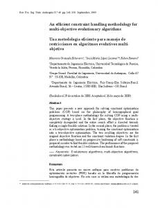
Fig. 1. Composition of basic and special register groups.
C. Composition of Registers In terms of hardware implementation, it is necessary to define a register type that represents the specific control property. Most pins of the general-purpose interface control block are multiplexed and have up to 15 different functions. The function of each pin can be configured by 4 bits of port configuration registers (PCONs). After reset, all port configuration registers have ‘0’ value in ROM boot mode. Thus, all pins are controlled by port configuration registers as input mode of a normal general-purpose interface control block. When ports are configured as output ports, data can be written on the corresponding bit of port data registers
(PDATs). When ports are configured as input ports, the data can be read from the corresponding bit of port data registers. For the port0 specified by one of the port control registers (PCTLs), the corresponding general-purpose interface pin will be set to 1 if the 8 bit-set part is 1 in a port control register, while no action will occur if the set part is 0.
16 functions as 4 bits in each pin, while the input data on the general-purpose interface control block indicates 8 pins in each port group.
The corresponding general-purpose interface pin will be set to 0 if the 8 bit-clear part is 1 in a port control register, while no action will occur if the clear part is 0. If the set and clear parts are both 1, then the value of the pin is toggled. This operation is performed only when the corresponding pins are designated as outputs of the port configuration registers. These actions are mainly for the purpose of checking the LCD interface on a field programmable gate array (FPGA). The pull up/down registers (PPURs/PPDRs) control the pull up/down resistors enable/disable of each port group. When the corresponding bit is 1, the pull up/down resistor of the pin is enabled. When the corresponding bit is 0, the pull up/down resistor is disabled. However, the pull up/down registers cannot be set to enable at the same time. For the ports and pins that are specified by the port number and pin number parts of the function selection register (FSEL), writing a number to the function part of the function selection register will copy that number to an appropriate place of the port configuration registers, and immediately change the function of the specified general-purpose interface. For example, writing 1110 and 1111 to the function part will cause two separate actions. Specifically, writing 1110 to the 4 bitfunction part will set the appropriate bits of the port configuration registers to 0001, and will set the lowest bit of the port data registers to 0. Writing 1111 will set the appropriate bits of the port configuration registers to 0001, and will set the lowest bit of the port data registers to 1. These actions are for the purpose of checking the interface connection to PAD to improve Design For Testability (DFT). The control properties of these register types can be extended in the future if necessary. The input enable registers (PPIEs) control the input enable pin of the general-purpose interface control block corresponding to each port group. When the corresponding bit is 1, the input data path is opened. When the corresponding bit is 0, the input data path is closed. These registers are particularly necessary for 45nm PAD structure to block leakage current which can flow through opened input paths before reset release. Therefore, these registers always need to be set to 1 for the correct operation of the input path after reset release. Also, these registers can be adaptively excluded by controlling the control property of a formalized text. D. Generation with the Proposed Formalized Text The auto-generator for a general-purpose interface control block is able to implement various functions with the formalized text in an automated way. The auto-generator for a general-purpose interface control block can generate a MUX and a control signal when the formalized text has registers described in Fig. 1. In Fig. 2, we show an example of the control signal generation for MUX. In this Fig., the formalized text defines a specific register to select one of the
Fig. 2. Signal generation approach of the auto-generator.
With the proposed input data on architecture described in Fig. 1, a designer can define the PAD control signals when the register type is defined as PPURs, PPDRs and PPIEs. One of the main advantages of the proposed scheme is that a designer can modify the control signals without changing signal definition which is already shared with the software developers. IV. EXPERIMENTAL RESULTS To demonstrate how our proposed approach using a formalized text can effectively auto-generate a generalpurpose interface control block, we used a display driver, a multimedia device, an image sensor and a mobile MPSoC platform, which were inspired by several Samsung projects based on 65nm and 45nm technology. Also, the autogenerator can adaptively generate RTL blocks that were compatible with 65nm and 45nm PAD structures. A fundamental execution model of our proposed RTL blocks auto-generator expressed in the Python script language has been proposed [11]. Implementation of the auto-generator requires a design decision that specifies the behavioral characteristics of the general-purpose interface control block. Further, such decisions may affect the choice of other features for the integration of the top level. Thus, it is recommended to use the formalized text as an input sequence which can minimize the possibility of restriction on the design decision. The core functions of the general-purpose interface control block are MUX control and data transfer to/from PAD. Therefore, sub-tasks corresponding to these functions can be parts of the main task to support the execution of the autogenerator, such as input/output MUX control and APB data transfer control.
To evaluate the efficiency of our proposed design approach, we applied our automated design to typical MPSoC platforms. We generated an architecture model whose hardware characteristics are summarized in Table 1. We measured the efficiency ratio of traditional RTL design time to RTL auto-generating time by our proposed RTL blocks auto-generator. TABLE I. GENERATION RESULTS FOR DIFFERENT MPSOC PLATFORMS USING FORMALIZED TEXT Item Platform Display Driver Multimedia Device
MUX
# PAD
Power
Data
Type
Control
Control
Control
4:1
3
No
Bit
8:1
3
No
Byte
Image Sensor
12:1
3
No
Byte
Mobile
16:1
4
Yes
Byte
As a result, the amount of manual description used to generate the general-purpose interface control block was reduced by the range of 96 to 98%, compared to the traditional RTL description. This automatic general-purpose interface control block generator is applicable to different platforms by simply changing the input formalized description text format. As shown in Fig. 3, we measured the size of the specification input and the generated RTL output to check the ratio in efficiency. Our proposed approach could reduce design time by automatically generating RTL blocks while simultaneously reducing the possibility of human error.
minimal amount of description effort. It is also not affected by manual errors that would occur because of frequent changes of RTL blocks in pin assignment. Moreover, our proposed auto-generator will enhance the reliability of integration of the top level with sufficient verification time, even though many registers and multiple I/O paths are usually fixed at relatively late stages of the design. In addition, designers can rapidly obtain RTL blocks by such an automated procedure. Hence, it is beneficial for enhancing the efficiency and reliability in the design of a general-purpose interface control block. Experimental results show that it is possible to describe various general-purpose interface control architectures with the proposed description format. Lastly, manual description for designing the general-purpose interface control block was reduced by a whopping 98%, compared to a traditional RTL description. ACKNOWLEDGMENT This work is partly supported by the National Science Foundation under Grant No. CCF-1065448. Any opinions, findings, and conclusions or recommendations expressed in this material are those of the authors and do not necessarily reflect the views of the National Science Foundation. REFERENCES [1] [2]
[3] [4] [5]
[6] [7] [8]
[9] [10]
[11] Fig. 3. Quantitative analysis in a typical MPSoC platform with description efficiency (output/input = 49%).
V. CONCLUSIONS In this paper, we have proposed an automated scheme for the design of a general-purpose interface control block, based on the process of a formalized text through our proposed autogenerator. By this formalized text, designers can specify an arbitrary general-purpose interface control block with a
[12]
[13] [14]
[15]
D. Gajski, A. Wu, V. Chaiyakul, S. Mori, T. Nukiyama, and P. Bricaud, “Essential Issues for IP Reuse”, in Proceeding of ASP-DAC, Jan. 2000. K. Cho, J. Kim, E. Jung, S. Kim, Z. Li, Y. Cho, B. Min, and K. Choi, “Reusable Platform Design Methodology for SoC Integration and Verification”, in Proceedings of ISOCC, Nov. 2008. V. Berman, “Standard: The P1685 IP-XACT IP Metadata Standard”, IEEE Design and Test of Computers, Apr. 2006. The SPIRIT consortium, “SPIRIT 1.2 specification”, www.spirit consortium.org, Apr. 2006. C. Lennard, “Industrially Proving the SPIRIT Consortium Specifications for Design Chain Integration”, in Proceedings of Design, Automation and Test in Europe, Mar. 2006 GenSys® Assembly/IO/Registers, http://www.atrenta.com/solutions/ge nsys-assembly.htm5 Duolog Technology, http://www.duolog.com/products/spinner/ N. Vijayaraghaven, B. Singh, S. Singh, and V. Srivastava, “Novel Architecture for on-chip AC Characterization of I/Os”, in Proceedings of IEEE International Test Conference, Oct. 2006. Z. Jianmin, and S. Shengyu, “Design and implementation of generalpurpose interface controller”, Microelectronics & Computer, Oct. 2004. W. Kruijtzer, P. Wolf, E. Kock, J. Stuyt, W. Ecker, A. Mayer, S. Hustin, C. Amerijckx, and S. Paoli, “Industrial IP integration flow based on IPXACT standards”, in Proceedings of Design, Automation and Test in Europe, Mar. 2008. Myoung-Seo Kim, Cheong Ghil Kim, Shin-Dug Kim, and Jean-Luc Gaudiot, “Design of Configurable I/O Pin Control Block for Improving Reusability in Multimedia SoC Platforms”, International Journal of Multimedia Tools and Applications, Jul. 2013. W. Wolf, A. A. Jerraya, and G. Martin, “Multiprocessor System-onChip (MPSoC) Technology”, IEEE Transactions on Computer-Aided Design of Integrated Circuits and Systems, Oct. 2008. A. A. Jerraya, and W. Wolf, Multiprocessor Systems-on-Chips, Morgan Kaufmann, Elsevier, 2005. M. Huebner, and J. Becker, Multiprocessor System-on-Chip: Hardware Design and Tool Integration, Springer Science+Business Media, LLC 2011. ARM, “AMBA”, http://www.arm.com/products/system-ip/amba/, Nov. 2012.