database and expert system to aid in fault isolation and repair planning for these
..... The implementation of the expert system is designed to be operated by.
NAVAL POSTGRADUATE SCHOOL Monterey, California WVSTAT4 •
DTIC ~FEB 17199
N
ooI
CD
ISYSTEM
THESIS AN EXPERT SYSTEM INTERFACED WITH A DATABASE TO PERFORM TROUBLESHOOTING OF AIRCRAFT CARRIER PIPING SYSTEMS by Irving B. Clayton III and Patsy R. Boozer December 1988
Thesis Advisor:
C. Thomas Wu
Approved for public release; distribution is unlimited.
894!
09
i
I
i
1-
i
Unclassified Security Classification of this page
REPORT DOCUMENTATION PAGE la Report Security Classification
Unclassified
lb Restrictive Markings
Distribution Availability of Report
2a Security Classification Authority 2b Declassification/Downgrading Schedule 4 Performing Organization Report Number s) 6a Name of Performing Organization 6b Office Symbol
3
Naval Postgraduate School
Naval Postgraduate School
I(If Applicable) 37
6c Address (city, state, and ZIP code)
Approved for public release; distribution is unlimited. 5 Monitoring Organization Report Number(s) 7a Name of Monitoring Organization 7b Address (city, state, and ZIP code)
Monterey, CA 93943-5000
Monterey, CA 93943-5000
8a Name of Funding/Sponsoring Organization
8b Office Symbol I(If Applicable)
8c Address (city, state, and ZIP code)
9
Procurement Instrument Identification Number
10 Source of Funding Numbers Elanan Number
Pt_
11
Title (Include Security Classification)
IPronct No
I Tak No
I Wik Unit Acmsimon No
An Expert System Inte rfaced with a Database System to Perform
Troubleshooting of Aircraft Carrier Piping Systems 12 Personal Author(s) 13a Type of Report
Clayton III, Irving B. and Boozer, Patsy R. 13b Time Covered To From
14 Date of Report (year, month,day)
I 15 Page Count
169 December 1988 16 Supplementary Notation The views expressed in this thesis are those of the author and do not reflect the official policy or position of the Department of Defense or the U.S. Government. 17 Cosati Codes I 8 Subject Terms (continue on reverse if necessary and identify by block number) Master's Thesis
Fi Id
I
Group
Subgroup
Expert System, Database, Modeling
Abstract (continue on reverse if necessary and identify by block number
Maintaining and troubleshooting aircraft carrierthrough tank piping systems is a labor intensive, operational fleet problem. There is a clear need for a useful database and expert system to aid in fault isolation and repair planning for these systems. The multiple extensive piping systems of an aircraft cmrier create an intimidating modelling problem for implementation in a database. The interface of an expert system to a large database to obtain improved execution speed, exploit a useful data model, reduce memory requirements, and enhance total system capability is examined and implemented. A flexible model for representing a large ship's piping systems in a database is presented. .,, . / 7 2. p.": )
20 Distribution/Availability of Abstract X ] unclassified/unlimited same as report
22a Name of Responsible Individual
C. Thomas Wu DD FORM 1473, 84 MAR
21 DTC users
Abstract Security Classification
Unclassified 22b Te]ephone (Include Area code)
(408) 646-3391 83 APR edition may be used until exhausted All other editions are obsolete
22c Office SymbolT.
152Wq security classification of this page
Unrlassified
Approved for public release; distribution is unlimited. An Expert System Interfaced with a Database System to Perform Troubleshooting of Aircraft Carrier Piping Systems by Irving B. Clayton III Commander, United States Navy B.S., University of Virginia, 1972 and Patsy R. Boozer Lieutenant, United States Navy B.S., University of South Carolina, 1979 Submitted in partial fulfillment of the requiremezits for the degree of MASTER OF SCIENCE IN COMPUTER SCIENCE from the NAVAL POSTGRADUATE SCHOOL December 1988 ( 2 Ir ng B. Clayto III
Author:z
'Patsy R. oozer Approved by: C.
omas Wu, Thesis Advisor
David K. Hsiao, Second Reader Robert B. McGhee, Chairman Department of Computer Science Kneale T. Marshal'
Dean of Information and Policy Scienc s ii
ABSTRACT Maintaining and troubleshooting aircraft carrier through tank piping systems is a labor intensive, operational fleet problem. There is a clear need for a useful database and expert system to aid in fault isolation and repair planning for these systems. The multiple extensive piping systems of an aircraft carrier create an intimidating modelling problem for implementation in a database. The interface of an expert system to a large database to obtain improved execution speed, exploit a useful data model, reduce memory requirements, and enhance total system capability is examined and implemented. A flexible model for representing a large ship's piping systems in a database is presented.
Accession For
GRA&
INTIS
DTIC T A Ui u o un od on juit f i "
[
0
Y
/
Disirrvibuition/ Availability Codes Dstl
.
l
llll i.lmllll II
I
IIIII~
I
I
l
'Ni
II
II
Avs l -and/or [Special
III
TABLE OF CONTENTS 1.
INTRODUCTION ............................................................. 1
II. BACKGROUND .............................................................
3
A. INTERNAL ARRANGEMENT .................................................. 3 B. TROUBLESHOOTING ................................................................ 5 I11. DESIGN AND IMPLEMENTATION ...................................... 8 A. MODELLING THE PIPING SYSTEM .......................................... 8 B. EXPERT SYSTEM .................................................................... 10 C. SOFTW ARE ............................................................................ 12 D. SCOPE OF PROTOTYPE .......................................................... 13 1. Damage Control Void ........................................................ 14 2. Fuel Oil Service Tank ........................................................ 14 3. Fuel Oil Storage Tank ........................................................ 14 4. Contaminated Tank ............................................................ 15 5. JP-5 Tank .......................................................................... 15 E. IMPLEMENTATION OF THE RELATIONAL MODEL ............... 15 F. PROTOTYPE DEMONSTRATION ............................................ 20 1. Database System Operation .................................................. 20 2. Expert System Operation .................................................... 23 IV. CONCLUSIONS ............................................................ 28 A. DATABASE SYSTEM/EXPERT SYSTEM CONNECTION ....... 28 B. REFINING THE PROTOTYPE .................................................. 29 C. POTENTIAL EXPERT SYSTEMS ............................................. 30
iv
APPENDIX
A.
DECISION TREES ............................................
APPENDIX
B.
RELATIONAL DIAGRAM .............................. 41
APPENDIX C.
PROGRAM LISTING ..................................... 42
31
LIST OF REFERENCES ........................................................ 159 INITIAL DISTRIBUTION LIST ............................................. 160
V
LIST OF FIGURES Figure 1. Figure 2. Figure 3. Figure Figure Figure Figure Figure Figure
4. 5. 6. 7. 8. 9.
Through Tank Piping Arrangement for No. 4. MMR ................ Basic Relation Diagram ....................................................... Contains Relation ................................................................ Pipesystem Relation ............................................................. Adjacent Relation ................................................................ Compartment Relation ........................................................ String 119S Compartments ................................................... Pipes Database Menu ............................................................ Database Query Menu ..........................................................
4 17 17 17 18 18 19 21 21
Figure 10. Figure 11. Figure 12.
Piping System Queries ........................................................ 22 Compartment Prompt .......................................................... 22 System Response to Query .................................................... 23
Figure 13. Figure 14. Figure 15.
All Pipes Contained in 8-119-9-V ......................................... Expert System Menu ........................................................... Problem Analysis Menu ......................................................
23 24 24
Fuel Oil Service Tank Problem Menu .................................... Prompt for Compartment Number ........................................ Action Prompt .................................................................... Troubleshooting Solution ....................................................
25 26 26 27
Figure Figure Figure Figure
16. 17. 18. 19.
Figure A.1 Figure A.2
31 D. C. Void Will Not Pump .................................................... D. C. Void Pumps but Refills with Water ................................ 32
Figure A.3 Figure A.4
Damage Control Void Will Not Flood .................................... 33 Damage Control Void Overflowing ....................................... 34
Figure A.5 Figure A.6 Figure A.7 Figure A.8
Water in a Fuel Oil Service Tank ......................................... Fuel Oil Service Tank Overflowing ....................................... Fuel Oil Service Tank Losing Fuel ........................................ Fuel Oil Storage Tank Overflowing ........................................
vi
35 36 37 38
Figure A.9 Large Contaminated Tank Ovefflowing .......................... Figure A.10 Fuel/Oil in a Damage Control Void ................................ Figure B.1 Relational Diagram.................................................
vii
39 40 41
I. INTRODUCTION The failure of aircraft carrier through tank piping was identified in the mid 1970's as a difficult management problem. The deterioration of carbon steel piping, from continuous immersion in salt water, allowed the intercommunication of the ship's fuel tanks and damage control voids. The potential detriment of intercommunicating tanks includes: " loss of boiler fires due to water in the fuel oil casualties • inadvertent overboard discharge of fuel when pumping a contaminated D.C. void " increased draft • reduction in ability to counter flood • lost reserve buoyancy The complexity of CV's, intense operating schedules, and advancing ship age has made dealing with piping casualties time consuming and frustrating. Hours spent tracing piping diagrams and making false starts in resolving a problem has pointed out that a formalized approach to the problem would be worthwhile. The system developed in this thesis is directly applicable to CV's 59/60/61/62/63/64, and is readily adaptable to CV's 41/43 and CVN-65. The CV-67 and CVN-68 class side protection systems, construction materials(copper-nickel piping), and pipe joining techniques(socket couplings) do not experience the same failures and hence these ships would derive minimal benefit from this system. The development of an expert system interfacing a large database to aid in troubleshooting aircraft carrier piping systems is divisible into three areas of emphasis:
" the model for the database system * the design of the interface to the database * the expert system itself This thesis examines each of these issues and implements the recommended solution in an operable database interfaced expert system. The implementation of the expert system is designed to be operated by Engineering Department personnel at sea on a micro computer likely to be readily available. The hardware limitations therefore are considered to be those of the Z-248, widely purchased for operating forces, and readily available as a GSA catalog item. CDR Clayton developed the decision trees and provided the expertise with respect to aircraft carrier design and construction.
The data model and user
interface to the system were also designed by CDR Clayton. LT Boozer developed the expert system, the interface to the data base, and the data base system.
2
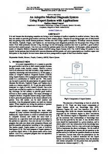
II. BACKGROUND The following are Naval terms which may need to be defined to assist in the comprehension of this paper: * "through tank" refers to long sections (40 - 50 feet) of pipe which run in the bottom of the ship through several adjacent compartments. These compartments are frequently other tanks, hence the label "through tank". " "string" refers to a group of tanks and voids all located side by side at the same frame number and on the same side of the ship. For example, string 119S refers to five adjacent voids and tanks all located at frame 119 on the starboard side of the ship. * "frame" is a relative location along the length of the ship starting at the forward end of the ship. Aircraft carrier frames are spaced at an interval of four feet, and are numbered sequentially bow to stem. * "wing tank" is a tank or void, outboard of the holding bulkhead, away from the center of the ship and in close proximity to the side of the ship. They are typically long (20 feet), narrow (5 feet), and very deep (37 feet). A. INTERNAL ARRANGEMENT Understanding the internal compartment and system arrangement in a FORRESTAL/KITTY
HAWK class aircraft carrier is fundamental
to
comprehending the database model utilized by the expert system. An illustration of a typical arrangement [Ref. 1:p. 101 appears as Figure 1. Piping emanating in the engineering spaces passes through several compartments before reaching its termination point. Aircraft carriers built prior to 1965 were constructed with mild carbon steel fuel oil transfer, fuel oil service, and fuel oil recirculating piping systems. The deterioration of these systems in service due to corrosion has resulted in leaks which are not readily apparent because they are inside of other tanks. This internal leakage is thus difficult to
3
I19
,1
,27
lf2
8-127--W FW
8-123-1-W FW
S-127-3-F FO
8123-3-W FW
8-119--W RFW
8-119-3"W RFW
__T
-
8-125V
J_, _
al, IDC
S-127-5-V
8-124-1-V
8-119-V
8-12T-7-V
8-124-3-V
6- 119-9 "V
8
1 1-11-
4
8-127-I1F FOS-5
-"
- I'! .,
-127-8-124-5F
OB2 8-124-7-F
a-S" 4
1
FOS 8-119-13F
4
4 e-127-13-V DC
Figure 1.
8-124-9-F 5 FOOS
2F
8-119-15-V DC
Through Tank Piping Arrangement for No. 4. MMR
4
diagnose. Other factors which contribute to the difficulty of diagnosing a problem are improper system operation by personnel, inoperative or leaking valves, foreign object blockage, and cracks in structure. Multiple combinations of the above factors can mask one problem from another and further complicate troubleshooting. This latter case presents the most difficult challenge to the expert system: successfully identifying more than one problem when multiple problems are present. The design of the expert system can accommodate this type of scenario with multiple independent user sessions, but careful decision tree structure can minimize these instances and identify more than one cause to a problem in a single session.
B. TROUBLESHOOTING The initial identification of a tank/void system problem can come from: •
soundings
•
tank level indicators
•
water at the boiler front
•
water paste tests
*
requirement to strip excessively
"
requirement to pump excessively
*
overflowing air escapes/sounding tubes
•
discharge from overboard piping
*
excessive draft
•
unable to pump The decision making process in troubleshooting a piping system casualty
begins with an input of what system is disrupted and what the initial symptom of the prc.-0em is. This information is brought to the attention of the Engineering Officer
5
of the Watch in Central Control, the work center supervisor in the oil/water lab, or the Damage Control Assistant. The trouble shooting process begins based on the experience and intuition of the individual to whom the problem is addressed. This, of course, is not a constant. The approach to solving a problem can vary widely between individuals, some who may have experienced a similar casualty and remembered a prior successful solution to that problem. A methodical process of elimination is the best approach to a solution, but thorough knowledge of the systems involved, the ship's construction, and accurate responses to questions are required to produce a least effort path to a solution. This is critical in an operating aircraft carrier because the demands of operating the ship in a normal state alone taxes the crew, correcting casualties quickly exhausts them. Because of this last condition, the first step in troubleshooting is to get as much accurate information as possible, with as little physical effort as possible. Simply put, you conserve energy. Actions which fall in this category are: * taking soundings " examining logs • making water paste tests * reading tank level indicators ° reading drawings and system technical manuals The next step, based on the above information, is to make simple tests using accessible equipment. These are: •
verify the correct line up of installed pumping/stripping systems in the machinery spaces * verify use of remote operating stations
6
disassemble small valves ( 4 inch or smaller ) in machinery spaces/pump rooms * listen to systems in operation • inspect equipment/systems in compartments which are readily entered (no bolted access covers). 0
Further escalation of troubleshooting should only begin when a problem has been isolated to a likely set of causes. Action at this point is one of the following categories: a open and gas free and inspect voids/tanks 0 open and pump tanks/voids using portable equipment * pump contaminated fuel/water out of the ship within the governing regulations for the location of the ship • disassemble large heavy valves (greater than 4 inches) pumps, or other complex equipment This sequence of actions is driven by conservation of assets and the need to minimize disruption of operating systems. The multiple possible paths to solving a unique problem, the varying level of experience of operators, and the importance of conserving assets, both time and personnel, clearly point to the need for an expert system capable of managing a complex object requiring a large number of facts stored in an organized database.
7
III. DESIGN AND IMPLEMENTATION The design and implementation of the total "PIPES" system involved the investigation of multiple alternatives of how to structure the system to maximize its performance with respect to: * model design and utility • storage of data " database query • modification/update of database * expert system power • memory requirements • speed * connection of software The following sections describe the evolution of the initial concept and understanding of the problem, through the decisions made in the development process, to the final configuration of the functional prototype system. A. MODELLING THE PIPING SYSTEM The initial concept of system design was to utilize a database management program to perform central program functions. This was primarily driven by the feeling that the difficulty in building the system would center around the details of the configuration of the model. The problem was viewed as a challenging database problem. This conclusion was drawn from the intimidating size and multiple attributes thought felt to be required to deal with a large object such as an aircraft carrier. There was also a defined set of queries which were clearly of the DBMS type. The intent was to solve the model problem, build a corresponding database
8
system, and then utilize an expert system to return troubleshooting problem solutions to the database system. The final configuration of the system, after evolving through the development cycle, is discussed in the Conclusions chapter. In making the choice of how to build the database model, consideration was given to traditional database structures. A hierarchical system offered no apparent utility in exploiting the cnstruction of the ship since there is no hierarchy among piping systems or the pieces of a piping system. The compartments within a ship could be hierarchically arranged by deck and by position from forward to aft in the ship but this did not provide any apparent advantage in dealing with the piping systems, so a hierarchical system was rejected. A network system appeared to be feasible but while attempting to establish the links in the data structure diagram for such a system it became clear that it would be easier to implement a relational model. The alternative of implementing the relational model in the expert system could have been accomplished, but would have required using an unmanageable number of facts in a Prolog system. This was judged to be prohibitive in terms of both memory requirement and speed of execution. Building a similar system in Pascal would have required an even larger quantity of code and would have again been a poor design choice for memory and speed reasons. A design decision was made to implement the database in a DBMS language to attempt to exploit the relational model which had been developed and which was thought to offer considerable potential because of its simplicity and apparent flexibility.
9
B. EXPERT SYSTEM The expert system function of the "PIPES" system is required to return solutions for specific problems selected by the operator. This meant that at least one fact is known at the outset of the session. One control structure for this type of rule based system is referred to as forward chaining. Essentially the expert system is given a fact and it then attempts to find a chain of facts which lead to a definitive conclusion. Control structures for expert systems are often combined to take advantage of the characteristics of each structure while compromising on the limitations brought with both structures. One form of such a combined control structure is called rule-cycle hybrid. Strictly defined, rule-cycle hybrid structures cycle through rules, in order, as in backward chaining, however, as facts are asserted they are added for use in the next cycle through the rules, as in forward chaining. [Ref. 2:p. 105] The nature of the problem solving done in troubleshooting shipboard piping systems led to the development of a system which employed a decision tree design where the entry point to a unique tree was a user selected problem. After entry into the tree, the user is directed to carry out troubleshooting action and then respond to questions as to the outcome of his investigations. In this manner virtual facts are established, as in forward chaining, through a series of user actions and responses which lead down the tree to a conclusion. Each rule which succeeds (establishing a virtual fact) thus leads to another rule which in turn must succeed (establishing another fact) to reach a conclusion. The design decision of how to connect the expert system to the database system presented the most difficult challenge in building the system. The available database programs provide no capability to make a call to another program, and return to the database program. A major
10
design change in the structure of the system was forced at this point of development. The details of this decision follow. The interface of a expert system to DBMS files can be accomplished by calling a specific data file from within the expert system. This would mean that none of the DBMS functions would be available for query or file modification without quitting the expert system and loading the DBMS. The alternative of loading the DBMS each time it was needed, and then reloading the expert system, though feasible, was regarded as an undesirable degradation, from an operator's performance perspective. An obvious alternative was to utilize a more advanced machine and run the expert system and DBMS simultaneously with a multi-processor, allowing queries to the DBMS without terminating the expert system. This method was judged unsatisfactory because of the requirement to be able to operate the system on shipboard available equipment, which at best would be 80286 processor based. Because the expert system can make calls to external data files, the feasibility of calling compiled DBMS program queries was examined. A limited number of software routines which would perform some DBMS functions were identified but not used because of the limitations on the nature of queries and prohibitive dollar cost. The potential performance improvement offered by this approach was a significant increase in speed over DBMS commands due to the machine language configuration of the already compiled routines.
A further option was to write
drivers in the DBMS program language to perform all of the required calls and returns from DBMS. By essentially duplicating explicit DBMS functions, the DBMS files could be queried and/or manipulated to return a response without the need to carry all of the DBMS's operating overhead and memory requirements. The drivers would, as compiled routines also did, significantly speed the response
11
of the database side of the system. Decomposing DBMS program code and writing appropriate routines was not in the scope of this thesis. The final design choice was a compromise to obtain the desirable modelling and data storage of the DBMS system and the efficiency of a Prolog expert system. The connection of the expert system to the DBMS was made by running the system from the DBMS system program and accessing the expert system by calling the already compiled executable Prolog file. The key to making this choice was recognition that the full Turbo-Prolog program was a compiled executable program [Ref. 3:p. 160] which could be run inside the d-BASE III program [Ref. 4:p. 208] and not exceed the 640K resident memory limitations of the hardware. An additional design decision was made to allow queries in the DBMS side of the system to be made both by using functions built for the DBMS program, and by a program feature provided to allow user built queries in d-BASE III, enabling full exploitation of the large database. This meant that some operator involvement was accepted to allow more complex DBMS queries to be made. C. SOFTWARE D-base III was selected as the database implementation software because it supports the relational database design. The use of the relational database was fundamental to the development of a useful model of the ship and its internal systems. D-base III is readily available to the potential users of the system and is relatively inexpensive.
Prolog was chosen for the expert system because it was
designed for artificial intelligence applications. Prolog solutions are arrived at by logically inferring one thing from something that is already known. A Prolog program is not a sequence of actions, but a collection of facts together with the rules for drawing conclusions from those facts. Prolog more closely follows
12
thinking than procedural programming languages, because it is a declarative language. A Prolog program for a given application will typically require only one tenth as many program lines as the corresponding Pascal program. Turbo-Prolog (Version 2.0) was selected for use in the implementation of the expert system because it was the latest and apparently best product available for use on the mandated IBM compatible hardware. It is a fifth generation language and, like d-BASE III, is both economical to purchase and readily available to potential users of the system developed in this thesis. D. SCOPE OF PROTOTYPE The development of the expert system to do troubleshooting of through tank piping system problems first required a problem statement of those casualties which the system must be able to solve. A decision was made to limit the scope of the expert system to those casualties experienced in the CV side protection system (wing tanks).
Although the
troubleshooting solution to these types of problems often extends into the machinery spaces and pump rooms, the initial problem areas dealt with by the expert system are those found among the menu items below as choices which are presented to the user: •
Damage Control Voids " Fuel Oil Service Tanks " Fuel Oil Storage/Ballast Tanks • Contaminated Tanks * JP-5 Tanks All of these menu selection tanks are wing tanks. This selection is the first decision a user is required to make in operating the program.
13
The development of the logic for initial symptoms of casualties is done in decision trees which are then coded in Prolog. Appendix A contains the logic decision trees for the implemented casualties. The menu items below appear depending on the selection of the tank type problem from the list of tanks above. Thus, the casualties handled by the system are: 1.
Damage Control Void
• Will not pump * Pumps but refills with water • Will not flood " Overflowing " Oil in a void " Sewage in a void Fuel Oil Service Tank
2. * • • " *
Water present Overflowing Foreign particles Losing fuel Gaining fuel 3.
* * * * *
Fuel Oil Storage Tank Water present Overflowing Foreign particles Losing fuel Gaining fuel
14
4.
Contaminated Tank
" overflowing * will not pump 5.
JP-5 Tank
" water present • overflowing * losing fuel ° will not strip * will not pump E. IMPLEMENTATION OF THE RELATIONAL MODEL Modelling a complex physical object is a principle challenge in designing many database systems. The creation of a satisfactory model of the multiple and extensive piping systems in an aircraft carrier was a primary area of research for this thesis. At the outset of implementing the expert system, one approach would have been to have used individual Prolog facts to describe the components of each system down to the requisite level of detail required to accomplish troubleshooting. This approach, while feasible, was judged to be unacceptably costly in memory requirements and execution speed. Simply stated, the number of facts was too large. The power of a database language was needed to structure, manipulate, and query the database in a manner which would take advantage of the properties of the system being modeled. Initial examination of Entity/Relationship models appeared to require considerable complexity to successfully model the system and its attributes. The requirements were to be able to uniquely identify each section of pipe within the
15
ship, to include location, system, and physical properties such as size and material composition.
Because the troubleshooting function of the expert system is
concerned with through tank piping, a model was developed which could be reduced to just four relationships, many fewer than was anticipated.
All the
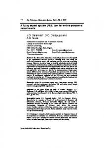
requirements could be met by careful placement of the attributes with the right relationship in the model, enabling the use of a surprisingly simple scheme. Although the model employed is fully adequate for this expert system, as implemented, it would require additional refinement to be expanded to model a machinery space or pump room. Because of the size of a main machinery room, simply identifying a pipe as being in the compartment is insufficient detail to be able to constructively utilize the model. An additional attribute is needed, for example "piping segment number" (piece number). This new attribute would be made up of the forward most frame number of a pipe within a compartment coupled to a port/starboard sequence number thus accommodating multiple pipe segr onts within a large compartment. The relational database developed and implemented in dBASE, uniquely identifies each pipe in the ship by the compartment number it is contained in, and the system that it is a part of. Thus the relation diagram (Figure 2) reduces to just four relations.
16
ICOMPARTEN
-A DRAC NT
CONTAINS
I PIPESYSTEM Figure 2.
Basic Relation Diagram
The CONTAINS relation (Figure 3) is keyed by compartment number to each pipe within that compartment. COMPARTMENT 8-119-9-V 8-119-9-V 8-119-9-V
SYSTEM FOS FOT FOT
NUMBER 8-119-11-F 8-119-13-F 8-119-11-F
Figure 3. Contains Relation represents a portion of the database describing which pipes are actually physically located in compartment 8-119-9-V. The PIPESYSTEM relation (Figure 4) System Number FOS 8-119-11 -F FOT 8-119-11-F FOT 8-119-13-F
Pipe System Fuel Oil Service Fuel Oil Transfer Fuel Oil Transfer Figure 4.
Size 4 5 5
Material Couplings steel N/A steel N/A steel N/A
Pipesystem Relation
depicts the noun name of the system, the size (diameter) of a pipe in inches, the material composition, and the type of joint make up used. These attributes are used
17
to maintain a current database for the configuration of the ship to support long term maintenance planning. The repairs include the replacement of deteriorated carbon steel piping, hence the material attribute, with copper nickel piping and the change of troublesome sleeve couplings with those of socket design, thus the coupling attribute. The size aids in the identification of a pipe when a tank/void is opened and inspected. The ADJACENT relation (Figure 5) ......... Compartment Forward 8-119-9-V
8-114-9-V
Aft
locates
Starboard
8-124-3-F 8-119-11-F
Port
Above
8-119-i-V 4-119-5-V
Figure 5. Adjacent Relation locates the compartment in the ship with respect to the other compartments and is used in troubleshooting logic and in maintenance planning to predict access and gas free requirements. The COMPARTMENT relation (Figure 6) String 119S
Usage Compartment Date Paint Date Completed Void
8-119-9-V
4-83
4-85
Figure 6. Compartment Relation identifies the string which a compartment is a member of, and records historical maintenance data pertinent to the entire compartment. The complete relational diagram appears in Apopendix B.1. Thus an apparently complex modeling problem was reduced to its fundamental relationships in a powerful relational database. The central relationship in this model and the basis for its power is the Contains relation. By subdividing the
18
aircraft carrier down to compartments, the common building block of the model, it becomes possible to depict the entire ship or only an area of the ship in which you are interested. In this thesis, for example, we only are interested in the fourth deck and below compartments. Thus everything above 45 feet above the keel (the height of the fourth deck) is not present in the database, because it is not relevant to through tank piping. By utilizing the Adjacent relation and the Contains relation it is possible to trace a pipe through the entire ship. For example, if compartment 8-119-9-V is a suspected problem void, the Adjacent relation tells us that there are compartments 8-119-7-V and 8-119-11-F inboard and outboard respectively of the problem void. The Contains relation then tells us that pipe system FOT 8-119-13-F (actually a section of pipe) is contained in each of three voids/tanks. We can thus trace this pipe through at least 3 compartments. If we look at the Pipe-System relation we find that FOT 8- 119-13-F is a fuel oil transfer pipe, 5 inches in diameter, and made of carbon steel. The Compartment relation tells us that 8-119-9-V, the original problem void, is in string 119S. Other compartments in string 119S appear in Figure 7. 8-119-1-W 8-119-3-W 8-119-5-F 8-119-7-V Figure 7.
8-119-9-V 8-119-11-F 8-119-13-F 8-119-15-V
String 119S Compartments
A check of Contains for these compartments reveals that pipe system FOT 8119-13-F originates in 8-119-5-F, passes through 7-V, 9-V, 11 -F, and terminates in 13-F.
The value of the compartment relation is that it identifies the
19
compartments in a string. From a given compartment, a string could be built by multiple calls to adjacent. Providing the relation minimizes repetitive manipulation of the database to obtain a frequently needed and useful fact. The relationship that may not be apparent is that most piping runs, run athwartship within the boundary of a string. The database design takes advantage of this property easing the modeling of a piping system by speeding the location of other compartments containing a section of pipe belonging to a specific system. Summarizing, the four relations contribute to the utility of the model as follows: * CONTAINS: identifies unique pipes in a compartment by pipe system * ADJACENT: locates a compartment within its surrounding compartments providing the mechanism for the building block concept in the model • COMPARTMENT: identifies the string a compartment is in, useful in that it relates a small group of compartments adjacent to each other within the ship " PIPE SYSTEM: allows the attributes of an entire system to be carried in a single tuple, rather than repeated for each compartment F. PROTOTYPE DEMONSTRATION The initial step in operating the system is to start "PIPES". The following screen displays will provide a demonstration of the steps required to operate both the d- BASE III portion of the system and how to enter the troubleshooting mode of operation performed by the expert system side of the system. 1.
Database System Operation The first menu (Figure 8) presented to the operator from the database
offers a choice system functions.
20
PIPES DATABASE Add/Edit Database Record Query Database Print Database Records Backup Database
A Q P B
PIPES - Expert System
E
Select Option Press ESC to EXIT Figure 8. Pipes Database Menu If the user desires to query the database, for an example, he would type "Q", which would bring up the database query (Figure 9) menu PIPES SYSTEM QUERIES Compartment Access Pipe Systems Adjacent tanks List of paint dates Select Option
C P A L A
Strings Tanks by type Inboard Tanks Unlisted Query
S T I Q
Press ESC to EXIT
Figure 9. Database Query Menu From the database menu the user presses the appropriate letter key. If he desired for example, to know the pipes in a compartment he would press "P". The piping system query menu (Figure 10) would appear:
21
PIPE SYSTEM QUERIES Pipes passing through compartment Compartments containing pipe system Specific pipe system material List of pipe systems by material Select Option: Press ESC to EXIT Figure 10.
P C S M
Piping System Queries
If it is desired at this point to know the specific pipes in a compartment, the user presses "P", which prompts him for the compartment number desired (Figure 11). COMPARTMENT TO QUERY Compartment No 8-119-9-V
Press ESC to EXIT Figure 11.
Compartment Prompt
The compartment number is entered by the user, as in the example above, "8-119-9-V" has been entered. The d-BASE III program at this point has sufficient input to conduct the query and respond. (Figure 12)
22
PIPE SYSTEMS PASSING THROUGH COMPARTMENT 8-119-9-V System Number: FOS 8-119-11-F
Press 58,VAL