An Extension of RDP Code with Parallel Decoding Procedure †
Jun Feng, †Yu Chen*, †Douglas Summerville, ‡Zhou Su
†
State University of New York – Binghamton, Binghamton, NY 13902, USA ‡ Waseda University, Ohkubo 3-4-1, Shinjyuku, Tokyo 169-8555, Japan
Abstract∗– XOR based RAID 6 systems outperform other RAID systems. Among the XOR (exclusive OR) based RAID-6 schemes, RDP has better performance than others by a narrow margin. However, the RDP code scheme cannot take full advantage of parallel hardware implementation of XOR codes. In this paper, we propose an extension of the double–erasure-correcting RDP code called EDP, which consists of a parallel decoding scheme. Thus, EDP can improve the decoding velocity of RDP by about 40% without any change to the current RDP configuration for storage. Keywords: XOR, Erasure Code, Fault Tolerate, Storage System.
without changing any disk configuration for RDP code. The only additional cost is to recover a missing parity in one extra step. However, after the step the EDP scheme can be effectively implemented in parallel on multiprocesser or reconfigurable hardware devices. The rest of this paper is arranged as follows. Section 2 provides background on RDP code. It focuses on the decoding algorithm that leads to the EDP scheme. Section 3 gives EDP decoding scheme. Section 4 presents experimental results. Section 5 concludes the paper.
1.
2.
Introduction
In modern storage systems, RAID (Redundant Array of Independent Disks) techniques are known to be the preferable ones that achieve higher performance and more reliability. RAID systems protect the data against disk failures by constructing redundant information and storing them on an array of hard disks. RAID-6, which can tolerate two failure-disks, has become more popular. Some RAID codes have been successfully designed to recover double storage node failures, including Reed-Solomon codes, EVEN-ODD [1], Row Diagonal Parity (RDP) [2] and Liberation codes [5]. X-code [7] an elegant two-erasure code, is not a RAID code. It does not meet the RAID-6 specification of having two independent parity devices, P and Q [5]. A recent examination on the performance of the codes for RAID-6 had concluded that special purpose RAID-6 codes vastly outperform their general purpose counterparts such as Reed-Solomon code, and RDP performs the best of these by a narrow margin [6]. However, the RDP code cannot take full advantage of parallel implementation of the multi-processer. For example, RDP code can start two iterative procedures at the beginning, but one of them has to stop quickly when it hits the block in the “missing” chain. This paper proposes EDP scheme (an Extension of RDP). It is an improved decoding method based on RDP. When implemented in parallel, the decoding velocity of EDP scheme can be improved by about 40% in theory * Manuscript submitted on July 8, 2011 to the 9th IEEE Consumer Communications and Networking Conference (CCNC 2012), Las Vegas, NV, USA, Jan. 14 – 17, 2012. Corresponding author: Yu Chen, Dept. of Electrical & Computer Eng., SUNY–Binghamton, Binghamton, NY 13902. E-mail:
[email protected], Tel.: (607) 777-6133, Fax: (607) 777-4464.
RDP Code
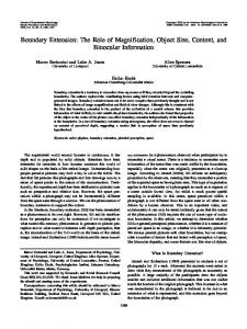
RDP uses the two slopes 0 and 1 to construct the parity devices P and Q. Figure 1(a) shows how parity blocks on the P device are created by data blocks, and Figure 1(b) shows the generation of parity blocks on the Q device. In Figure 1(b), the yellow colored blocks are imaginary blocks. In order to avoid confusion and inconsistency, we equal “n” to a prime number, the number of data disks is n-1 by default. If it is less than n-1, we can suppose there are imaginary data disks to form the n-1 data disks. Each disk has n-1 blocks. So the storage can be considered at as n-1 rows × n+1 columns array. One column stands for a disk. We use “i” to specify the rows and “j” to the columns. If two disks failed, we mark them as “a” and “b”, where a < b. We call the set of blocks in one line to generate parity x the “chain x”. For example, the set of {q0, p1, d23, d32, d00} is chain q0. There are five parity chains for the Q device generation, but there are only four parity blocks in the Q device. Since one of the parity blocks cannot be stored in the Q device, the corresponding chain
(a) P device construction.
(b) Q device construction.
Figure 1. RDP encoding procedure (n=5).
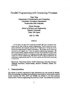
is called the “missing chain”. There is no restriction on which diagonal should be selected to store parity blocks. By default, diagonal n−1 is the missing diagonal. The idea of the decoding process will be illustrated by an example. Assume that data devices 1 and 3 are erased. In this example, two starting chains, q0 and q2, can be found. The two missing blocks d23 and d11 are reconstructed immediately. Then, the row parity can be used to recover two more missing blocks d21 and d13 in the two rows. Then, because the block d13 lies on the missing chain, it cannot start the next recovery process. It has to stop. The remaining failed blocks have to be recovered by another iterative process one by. Figure 2 illustrates that the sequence for the recovery procedure.
Step #1: calculates the accelerator: n −2
qn −1 = ⊕ qi
(1)
i=0
where qn-1 is the parity of the missing chain. Step #2: Run the RDP decoding procedure. Below is a short proof of Equation (1). Proof: Let’s define qi = Qi ⊕ pi+1, where Qi is the parity of the data blocks in the chain. Then, q0 = Q0 ⊕ p1, … qn-1 = Qn-1 ⊕ pn. Suppose all imaginary data blocks are zero. Then their n −1
n −1
parity result pn-1 is zero. ⊕ pi is equal to ⊕ Qi because i=0
i =0
both of them are XOR result of all data blocks. Then: n−2
n−2
n −1
⊕ qi = ( ⊕ Qi ) ⊕ ( ⊕ pi )
i=0
i =0
i =1
n −1
n −1
= ( ⊕ Qi ) ⊕ ( ⊕ pi ) ⊕ Qn −1 ⊕ p0 = Qn −1 ⊕ p0 = qn −1 i =0
i=0
For example, in Figure 1, we have q0 ⊕ q1 ⊕ q2 ⊕ q3
Figure 2. Illustration of the RDP decoding procedure.
Figure 2 also shows that when one of them hits the missing parity chain and stops another chain can traverse the remaining erased data blocks. Since a recovery time depends on the long chain, if each of the two iterative processes recovers half of the erased blocks in parallel, the recovery process can achieve the highest decoding efficiency. Based on this observation, we proposed the EDP method that achieves the highest speed by making each chain recover half of the lost blocks in parallel.
3.
EDP Decoding Scheme
EDP decoding scheme can be described as “accelerator plus the RDP decoding algorithm”. The advantage this scheme offers is that the current RDP based systems can be upgraded to the new EDP based systems smoothly without any change, which is preferable for users. In this section, an overview of various missing data scenarios is first introduced, and then the theoretical foundations of the EDP code are discussed. In subsection 3.3, the detailed EDP decoding algorithm is presented. Since it is trivial to recover a single failed column, this section describes how to recover two failed data devices which is most likely to occur. It is infeasible to recover the failed blocks separately. The scheme consists of two steps.
= Q0 ⊕ p1 ⊕ Q1 ⊕ p2 ⊕ Q2 ⊕ p3 ⊕ Q3 ⊕ p4 = (Q0 ⊕ Q1 ⊕ Q2 ⊕ Q3) ⊕ (p1 ⊕ p2 ⊕ p3 ⊕ p4) = (Q0 ⊕ Q1 ⊕ Q2 ⊕ Q3 ⊕ Q4) ⊕ (p1 ⊕ p2 ⊕ p3 ⊕ p4 ⊕ p0) ⊕ Q4 ⊕ p0 = Q4 ⊕ p0 = q4. Theorem. Assume there are two columns a and b in the array, where 0≤a