IJRIT International Journal of Research in Information Technology, Volume 2, Issue 6, .... is basically a scaled down ve
IJRIT International Journal of Research in Information Technology, Volume 2, Issue 6, June 2014, Pg: 103-108
International Journal of Research in Information Technology (IJRIT) www.ijrit.com
ISSN 2001-5569
An FPGA Implementation of 8-Channel Arbitrary Waveform Generator for Medical Ultrasound Research Activities Abilash K #1, Marina Chandy#2 #1 #2
E&CE Department, Srinivas Institute Of Technology,Valachil Mangalore,574143 1
[email protected] [email protected] 3
[email protected]
Abstract—In this document we are presenting a new approach to design an optimized 8-channel waveform generator for medical ultrasound research activities by using Digital Frequency Synthesizer (DFS) for complex demodulation used in digital receivers. Commercial ultrasound (US) equipment, although widely employed in diagnostic applications, is not suitable for the development and test of new investigation methods. Their typical architecture, designed for clinical use, is often “closed” and does not fit the requirements of flexibility, data access, programmability, which are necessary for the implementation of original approaches. More flexibility is achieved in high-level platforms, but they are typically characterized by high cost and dimensions. In this paper, a novel US system, specifically designed for research purposes, is presented. Its architecture is based on hi-end programmable devices to obtain the maximum flexibility with minimum cost and size. Ultrasound is used extensively in the field of medical imaging. In this paper, the basic principles of ultrasound are explained using ‘everyday’ physics. In this scheme the communication exists between the FPGA board and laptops. The simulation results show that the system is available. In this project, we implement the 8-channel waveform generator which is synthesized and simulated on FPGA family of Spartan-3(XC3S400) using Xilinx ISE 12.2 tool in Very high speed integrated circuit Hardware Description Language (VHDL) and shall be verified with the help of its simulation result.
KEY WORDS— Digital Frequency Synthesizer, FPGA, VHDL, Ultrasound I. INTRODUCTION Ultrasound has been used to image the human body for over half a century. Dr. Karl Theo Dussik, an Austrian neurologist, was the first to apply ultrasound as a medical diagnostic tool to image the brain. Today, ultrasound (US) is one of the most widely used imaging technologies in medicine. It is portable, free of radiation risk, and relatively inexpensive when compared with other imaging modalities, such as magnetic resonance and computed tomography. Furthermore, US images are tomographic, i.e., offering a “cross-sectional” view of anatomical structures. The images can be acquired in “real time,” thus providing instantaneous visual guidance for many interventional procedures including those for regional anesthesia and pain management. In this chapter, we describe some of the fundamental principles and physics underlying US technology that are relevant to the pain practitioner. Ultrasonic imaging is the second most popular imaging modality in medicine (the first being x-rays). It is estimated that over 25% of all medical imaging procedures involve ultrasound. Ultrasonic imaging complements the other major imaging modalities, i.e. x-rays and magnetic resonance (MR) imaging etc. Ultrasonic imaging is used extensively in obstetrics (figure 1(a)). For example, the size and weight of a baby can be estimated
Abilash K,IJRIT
103
IJRIT International Journal of Research in Information Technology, Volume 2, Issue 6, June 2014, Pg: 103-108
by measuring the diameter of the head, abdominal circumference and femur length on an ultrasound image. If the time since conception is known, then the projected weight of the baby at birth can be estimated. Two-dimensional (2D) ultrasound images can be combined together to produce three-dimensional (3D) images of a fetal face. Studies have shown that congenital abnormalities are easier to detect using 3D images than 2D images. Ultrasound is also used extensively to image the heart and to measure blood flow in arteries and veins (to detect blockages, for example). Ultrasound, as the name implies, is sound that is so high pitched that it is beyond the range of human hearing. Sound is considered to be ultrasonic if the frequency is above 20 kHz. (NB: Sound of a frequency below the lower frequency threshold of human hearing, ~ 20 Hz, is known as infrasound.) Some animals, e.g. bats and dolphins, use ultrasound to locate objects. Bats emit sound at a frequency of about 25 kHz, and dolphins around 125 kHz. If you lived near some bats when you were a child, you could probably hear them. Adults cannot hear bats as the frequency range of human hearing gradually reduces with age from a peak in childhood of about 25 kHz. Ultrasound as a medical imaging modality was developed in the 1950s and is really an application of SONAR (Sound Navigation and Ranging) to imaging the human body. If we think for a moment how SONAR works, we will understand the basic principles of the production of ultrasound images. In SONAR, a pulse of sound (a high pitched ping) is sent out into the ocean. If the sound hits a solid object, e.g. the hull of a submarine, the sound is reflected back and is picked up by an underwater microphone called a hydrophone. As the name SONAR implies, an object is located by knowing the direction and distance of the echoes. A blob of light is plotted on a display unit, indicating the presence of an object at a certain direction and range. The range of a structure causing the echo is calculated from the product of the time delay between the emitted and return pulses and the velocity of sound in seawater (~ 1510 ms−1). The result needs to be divided by a factor of 2 since the sound has travelled out to the reflecting structure and back again. For example, if an echo returns after 2 s the range of the reflecting object is ~ 1.5 km. Medical ultrasonic imaging is basically a scaled down version of SONAR in the ocean, although, of course, there are important differences. One difference is that SONAR is in the audible range of frequencies—in fact, if you happen to be swimming underwater within a few km of a ship using SONAR it is possible to hear the pings. Ultrasound emitted from a medical transducer is of much higher frequency—typically in the range 3–7MHz. The reason for using a much higher frequency than audible sound is to obtain high-resolution images.
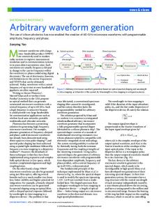
II. IMPLEMENTATION OF DIGITAL FREQUENCY SYNTHESIZER Simplified form of DFS is shown in Fig.1. It consists of a phase accumulator and a phase to amplitude converter (conventionally a sine ROM).The phase accumulator consists of a j bit frequency register, which stores a digital phase increment word followed by a j bit full adder and a phase register. The digital phase increment input word is entered in the frequency register. This data is added to the data previously held in the phase register at each clock pulse. The phase increment word represents a phase angle step that is added to the previous value at each ( 1 / fclk ) second to produce a linearly increasing phase value. The phase is generated by modulo 2 j overflowing property of a phase accumulator. • A clock with frequency clk f is the synthesizer’s only time reference. The phase accumulator’s output is a ramp value, as it overflows to 0 periodically. For an N-bit accumulator, the frequency of the ramp is given by
Every value at the output of the phase accumulator is converted to approximated sine amplitude by a phase-to-sine amplitude converter.
• The spectral purity of the DFS is estimated by the values stored in the sine table ROM. Hence can increase the resolution of the ROM. But as ROM storage increases lower the speed, increased power consumption and greatly increased costs. By storing only Π/2 radians of sine wave information compression can be achieved and to generate the ROM samples for the full range of 2Π by exploiting the quarter wave symmetry of the sine function. One of the approaches to the phase-to-sine amplitude mapping is the CORDIC algorithm, which is an iterative computation method. But there is increased circuit complexity, cost and distortions that will be generated, when the methods of memory compression are employed.
Abilash K,IJRIT
104
IJRIT International Journal of Research in Information Technology, Volume 2, Issue 6, June 2014, Pg: 103-108
Fig.1. Implementation of DFS and its waveforms. Technique to store only Π / 2 radians of sine information and to generate the sine look-up table samples for the full range of 2Π quarter-wave symmetry of the sine function is used. The decrease in the look-up table capacity is paid for by the additional logic necessary to generate the complements of the accumulator and the look-up table output. The two Most Significant Bit (MSB) s are used to decode the quadrant, remaining k-2 bits are used to address a one-quadrant sine look-up table. MSB determines whether the amplitude is increasing or decreasing. The accumulator output is used “as is” for the first and the third quadrants. The bits must be complemented so that the slope of the saw-tooth is inverted for the second and fourth quadrant. The sampled waveform at the output of the look-up table is a full wave rectified version of the desired sine wave as shown in Fig. 2. The final output sine wave is then generated by multiplying the full wave rectified version by -1, when the phase is between Π and 2Π.
Fig 2 Detailed diagram of DFS Instead of a ROM LUT, a hardware-optimized phase-to-sine amplitude converter used to approximate the first quadrant of the sine function with eight equal-length piecewise linear segments. The main goal is to maintain low system complexity and reduce power consumption and chip area requirements. The second aim is to achieve a specified spectral purity, where spectral purity is defined as the ratio of the power in the desired frequency to the power in the greatest harmonic, across tuning bandwidth of the synthesizer. Spectral purity is an essential design parameter in communication systems for synthesizer, ensuring that undesired in-band signals remain below a given threshold and are not detected. In order to achieve the first goal, approximation of a sinusoid as a series of eight equal-length piecewise continuous linear segments si is done, where Si(x) = mi * (x – i/8) + yi i∈ [0,7] is the slope of each segment and is carefully selected to eliminate the requirement for multiplication by representing each one as a sum of at the most two powers of two. Precision of slope representation, i.e., the difference between the smallest and the largest powers of two used can restrict, by putting an upper bound on the adder’s width. To reduce the control system circuitry costs equal length segments are selected. In order to obtain desired spectral purity, different sets of mi and yi coefficients are evaluated and the best one meeting the requirements is selected.
Abilash K,IJRIT
105
IJRIT International Journal of Research in Information Technology, Volume 2, Issue 6, June 2014, Pg: 103-108
Fig.3. DFS architecture
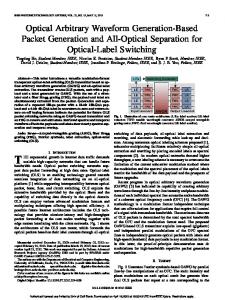
III OVERALL SYSTEM ARCHITECTURE Complete DFS architecture is shown in Fig.3.The coefficients are given in Table 3.1. The phase to sine amplitude converter block includes a 1’s complement to exploit quarter wave symmetry. This architecture is significantly less complex. It does not include a ROM, no multipliers or squaring circuits are required. To simplify the control circuitry equal length segments are used. Only three integers need to be added and multiplexers. • The phase accumulator is of 20 bits wide, truncated to 12 bits. The two MSBs are used for quadrant symmetry. Segment is identified by the next three bits. The remaining seven bits identify different sub-angles. The two upper multiplexers shift these remaining seven bits according to the slopes mi, listed in Table 3.1 Table 3.1: Linear segment coefficients
•
The notation {>>n} shown in Fig.3 signifies a right shift by n bits, means division by 2n. The lower multiplexer selects the appropriate yi approximation listed in the table. The output from the multiplexers is of 13 bits wide, to account for the whole dynamic range of possible values. The three-operand adder sums the multiplexer outputs together and rounds the result to 7 bits.
.
IV. IMPLEMENTATION AND TESTING The FPGA that is used for the implementation of the circuit is the Xilinx Spartan 3E (Family), XC3S500 / XC3S1600 (Device), FG320 / FG484 (Package), -5 (Speed Grade). The working environment/tool for the design is Xilinx ISE 9.2i.
Abilash K,IJRIT
106
IJRIT International Journal of Research in Information Technology, Volume 2, Issue 6, June 2014, Pg: 103-108
Fig 4 FPGA kit The Spartan-3E Starter Kit board highlights the unique features of the Spartan-3E FPGA family and provides a convenient development board for embedded processing applications. The board implements the design and verifies that it meets the timing constraints after check syntax and synthesis. DFS architecture can be used to perform modulation & demodulation in communication system. To verify the architecture, the design was coded in VHDL. Fig. 7.1 shows the simulation result of DFS architecture for offset value 111111.
Fig 5 phase accumulator output
Fig 6 DFS output
Abilash K,IJRIT
107
IJRIT International Journal of Research in Information Technology, Volume 2, Issue 6, June 2014, Pg: 103-108
Fig 7 simulation output V. CONCLUSION In this project we describe the design and performance of a programmable 8-channel arbitrary waveform generator for the development of new US investigation methods. The flexible transmission FPGA-based platform was implemented using a reasonably inexpensive. FPGA test board and a house made digital frequency synthesizer board, which can be connected to any commercial PC through RS232 port. Experimental results show that this technique is suitable for generating the excitation waveforms needed for medical ultrasound imaging researches. This system provides the access to ultrasound researchers suitable for the development and test of new investigation methods. Use of DFS architecture has helped to reduce the power requirements than commercial ultrasound devices. Its output frequency can be precisely and rapidly manipulated. A compact and cost-effective method for generating simultaneous arbitrary waveforms over several channels is presented. Delay elements can be added in future. Here we are concentrated more about output frequency, phase and amplitude can be implemented in future. REFERENCES 1. Deprettere, E., Dewilde, P., and Udo, R., "Pipelined CORDIC Architecture for Fast VLSI Filtering and Array Processing," Proc. ICASSP'84, 1984, pp. 41.A.6.1-41.A.6.4. 2. Anupama B R, M C Chandrashekhar, Dr. M Z Kurian, “Implementation of a GMSK Communication System on FPGA Using Distributed Algorithm”, International Journal of Advanced Research in Electrical, Electronics and Instrumentation Engineering ,Vol. 2, Issue 6, June 2013. 3. Direct Digital Frequency Synthesizer with CORDIC Algorithm and Taylor Series Approximation for Digital Receivers, Maher Jridi, European Journal of Scientific Research ISSN 1450-216X Vol.30 No.4 (2009). 4. Efficient Transmit Beamforming in Pulse-Echo Ultrasonic Imaging,Gabriella Cincotti, Giovanni Cardone, Paola Gori, and Massimo Pappalardo. 5. Arbitrary Waveform Coded Excitation Using Bipolar Square Wave Pulsers, Sheng-Wen Huang and Pai-Chi Li. 6. A Low-Cost Bipolar Pulse Generator for High-Frequency Ultrasound Applications Xiaochen Xu, Student Member, IEEE, Jesse T. Yen, Member, IEEE, and K. Kirk Shung, Fellow, IEEE. 7. Multichannel FPGA-based arbitrary waveform generator for medical Ultrasound, S. Ricci, L. Bassi, E. Boni, A. Dallai and P. Tortoli. 8. A Novel Digital Ultrasound System for Experimental Research Activities L. Bassi, E. Boni, A. Cellai, A. Dallai, F. Guidi, S. Ricci, P. Tortoli
Abilash K,IJRIT
108