colleagues applied the median filter to the noise corrupted image in Figure 1.1. The location of ... passes of the median filter of window width 3 will eventually drive a signal of finite length ... respect to different noise types is why it was able to recover the copper corner cube in the ...... which makes hard decisions. This follows ...
CIRCUITS SYSTEMS SIGNAL PROCESS VOL. 11, NO. 1, 1992
AN OVERVIEW OF MEDIAN AND STACK FILTERING* M o n c e f Gabbouj, 1 Edward J. Coyle, 2 and Neal C. Gallagher, Jr. 2
Abstract. Within the last two decades a small group of researchers has built a useful, nontrivial theory of nonlinear signal processing around the median-related filters known as rank-order filters, order-statistic filters, weighted median filters, and stack filters. This required significant effort to overcome the bias, both in education and research, toward linear theory, which has been dominant since the days of Fourier, Laplace, and "Convolute." We trace the development of this theory of nonlinear filtering from its beginnings in the study of noise-removal properties and structural behavior of the median filter to the recently developed theory of optimal stack filtering. The theory of stack filtering provides a point of view which unifies many different filter classes, including morphological filters, so it is discussed in detail. Of particular importance is the way this theory has brought together, in a single analytical framework, both the estimation-based and the structural-based approaches to the design of these filters. Some recent applications of median and stack filters are provided to demonstrate the effectiveness of this approach to nonlinear filtering. They include: the design of an optimal stack filter for image restoration; the use of vector median filters to attenuate impulsive noise in color images and to eliminate cross luminance and cross color in TV images; and the use of median-based filters for image sequence coding, reconstruction, and scan rate conversion in normal TV and HDTV systems.
1.
Introduction
Linear filters have long been the primary tool for signal and image processing. They are easy to implement and analyze and, perhaps most importantly, the linear filter which minimizes the mean squared error criterion can usually be found in closed form. Furthermore, they are optimal a m o n g the class of * Received January 2, 1991. 1 Research Institute of Information Technology, Tampere University of Technology, P.O. Box 527, SF-33101 Tampere, Finland. 2 School of Electrical Engineering, Purdue University, West Lafayette, Indiana 47907, USA.
8
GABBOUJ,COYLE, AND GALLAGHER
all filtering operations when the noise being considered is additive and Gaussian. Unfortunately, a small deviation from this Gaussian assumption sometimes leads to a severe deterioration in the performance of linear filters. In the many applications in which non-Gaussian noise arises, linear methods have thus proven to be inadequate for signal smoothing and noise reduction. One such case occurs in the presence of speckle noise. Other types of non-Gaussian and/or signal-dependent noise also cause problems. We believe that these cases occur more frequently than not; therefore, linear methods are not completely satisfactory when dealing with real signals and noise rather than simply computer simulations. For a concrete example, consider the experiment conducted by Dr. J. Johnson of Redstone Arsenal. The image shown in Figure 1.1 is the original
I
Figure 1.1. Image before median filtering. This is an original two-dimensional image obtained by Dr. J. Johnson of Redstone Arsenal with an experimental laser imaging system at the far infrared wavelength of 1.2 mm. The image was obtained by scanning the laser over a scene consisting of a highly reflective copper corner cube sitting on a table with a forest in the background. If there was no noise, the image would appear as a black square, the return from the copper corner cube, on a gray background, the return from the forest and the table. The location of the cube is not apparent, though, because of speckle noise, thermal noise in the receiver, fluctuation in the laser beam's intensify, and other noise sources.
AN OVERVIEW OF MEDIAN AND STACK FILTERING
9
two-dimensional image obtained with an experimental laser imaging system at the far infrared wavelength of 1.2 ram. The image was obtained by scanning a laser beam over a scene consisting of a highly reflective copper corner cube sitting on a wooden table with a forest in the background. In the absence of any noise, the image would appear as a solid black square, the return from the cube, on a gray background, the return from the forest and the table. However, the picture in Figure 1.1 shows no trace of any meaningful object. This is due to the speckle-noise, thermal noise in the receiver, fluctuations in the intensity of the laser beam, and other noise sources. Attempts with numerous linear filters on this image all failed. One reason for these failures is that both the impulsive structures created by the speckle and the edges of the cube are high-frequency components. Any linear filter designed to suppress the impulses would necessarily blur the edges in the image as well. Another reason for their failure was mentioned earlier: linear filters are optimal only when the noise is additive and Gaussian, while speckle noise is far from Gaussian, is not additive, and is not even independent of the signal. So what should be done to solve this problem? The answer is to use a filter that is not linear. There are, however, many classes of nonlinear filters, and the task of choosing the right class is itself a challenge. Each class of filters is good in certain applications. The user could consult a look-up table to determine which filter or class of filters best fits the problem at hand. One filter that would certainly appear in any such catalogue would be the median filter--the filter suggested by Gallagher for the image in Figure 1.1. The median filter, or "running median" as it was mentioned in the first publication in which it appeared [129] and was elaborated on in [130], consists of a window, usually of odd width, which is stepped one sample at a time along a signal. At each position of the window, the sample values inside are ranked according to their magnitude and the middle element in this ranking is defined to be the output. Typically, the window is assumed to have width 2N + 1 where N is any positive integer. Suppose that the window is centered on the kth sample in the input sequence and that the 2N + 1 points in the window, in time order, are specified by the vector ( X k - N , X k - N + ~, " ' , Xk, . . . , Xk+N).
We want to find Yk, where Yk = m e d i a n ( x k - N,
X k "N + 1 . . . . .
X k + N)
(1.1)
which is the output of the median filter when the window is centered on the kth sample of the signal. First, the samples in the window are reordered according to their rank,
10
GABBOUJ, COYLE, AND GALLAGHER 5-
9
[ _-s:I
4oe
I l
3 - 2 -~---i~--
•
--1 l-t_
-. = o Input g
I
0
9
Filter MOIilXl
5 4c~.: 3 2 1 0
,~ :
9 o 4 :
."
O~tput
- -
Figure 1.2. The operation of the window width 3 median filter, o: appended point.
with x(i) denoting the sample of ith rank. The samples in the window, in rank order, would then be (X(1), X ( 2 ) , ' ' ' ,
X(2N+I))'
Suppose, for instance, that N = 2 and that the samples, in time order, in the window are (Xk_2, Xk_l, Xk, Xk+l,
X k + 2 ) = (8,
1, 6, 4, 1);
in rank order they would be (x(1), x(21, x(3), x(43, x(s)) = (1, 1, 4, 6, 8). The median value of 2N + 1 samples is given by X(N+ 1), which for the example just given would be x(3) = 4. We thus have Yk = 4. The window is then moved so it is centered over the (k + 1)st sample in the input sequence and the output value Yk+, is computed by following the above procedure. Figure 1.2 shows the input and output for a window width 3 median filter, and also shows how the window moves along the signal. Note from the figure that the median filter can preserve edge structures while deleting impulsive strtictures. Note that near the beginning or end of a finite length sequence, some output values will be undefined because some samples will be missing from the window. One technique [130] for circumventing this problem is to repeat the endpoints of the sequence a sufficient number of times to fill up the window even when it is centered on an endpoint. If the window has width 2N + 1, then the endpoints must be repeated N times. In Figure 1.2, note that each endpoint must be repeated once since the window has width 3, which means that N = 1. We are, of course, also interested in applying the median filter to two-dimensional signals like the one in Figure 1.1. There is a great deal of freedom in extending the median to two dimensions. One of the most
AN OVERVIEW OF MEDIAN AND STACK FILTERING
l1
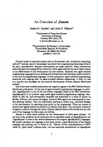
Figure 1.3. Image after median filtering. Upon our suggestion, Dr. Johson and his colleagues applied the median filter to the noise corrupted image in Figure 1.1. The location of the copper corner cube, which was obscured in the original image, is now apparent as the dark region in the center near the top. None of the other filtering techniques that were tried produced results as good as these. common methods is called separable median filtering [773, [86], [90], [98]. To filter the image in Figure 1.1 with a 3 x 3 separable median filter, a window width 3 median filter is first run along each of the rows of the image to produce an intermediate image, and the median is then run along each of the columns of this intermediate image to produce the final image shown in Figure 1.3. Note that the location of the copper corner cube, which was obscured in the original image, now very clearly appears as the dark region in the center near the top of the picture. Now, the question is: Why did the median filter perform so well in this application? For the last few decades, this question has attracted the attention of m a n y researchers. The result of this attention is a large number of papers, dissertations, and books written on median and median-related filters. In the following three subsections we present a literature review on this subject. Due to lack of space, some of the work in "this field might not be listed here, please refer to the recent book by Pitas and Venetsanopoulos [107] and the bibliography in [34] for additional references.
12
GABBOUJ,COYLE,
AND GALLAGHER
5 4
1 c-e::
2
I
0
5 4 c=== 3
2
l-'o0 -':I
I *
I
::::--
I
~ t e r Motion
i 9149 9
!
== 9
o
Output
1.4. A median filter root signal. The signal shown above is a root signal for a window width 5 median filter. Roots for this filter consist of alternating nonincreasing and nondecreasing regions separated from each other by constant-valued regions at least three points long. Notice that sharp edges are allowed in a root signal, but not impulses. Figure
1.1. Theoretical analysis of median filters In the 1970s Tukey [129], [130, p. 210] introduced the "running median" as a tool for smoothing discrete data. Since then its name has changed to "median filter," and it has been used in several areas of digital signal processing, including speech processing [66], [117], image enhancement [67], [111], [121], and biochemical data analysis [18]. Some of the earliest theoretical results on the behavior of the median filter concerned the existence and nature of its invariant signals, or root signals. An example of a root signal is provided in Figure 1.4, in which it is easy to see that the input and output signals are the same. In [130] several examples are given which demonstrate that successive passes of the median filter of window width 3 will eventually drive a signal of finite length to a signal which is invariant to further passes of the filter. The locally monotone nature of these finite-length fixed points was observed in [17], [130], [134] and then proven for all median filters of odd window width by Tyan [131], [132] and Gallagher and Wise [54]. If the signals being considered are infinite in length, then not all root signals are locally monotone; those that are not must be bivalued [131], [132]. Gallagher and Wise [54] also showed that any finite-length signal is filtered to a root signal after a finite number of passes of a median filter of a fixed window width. This is an important result--it ties median-type filters to neural nets since such convergence behavior is the primary characteristic of associative memories. The root signals represent eigenfunctions for the filter and are therefore fundamental to the properties of the filtering operation. Results on the number of binary and multilevel root signals for median filters for various window widths were provided in [9], [45], [138], and [-144]. The tightest known bound on the number of passes of the median
AN OVERVIEW OF MEDIAN AND STACK FILTERING
13
necessary to reach a root can be found in [138]: if the filter window width is 2N + 1 and the signal has length L, then at most
i2{ 72)i passes of the filter are required to reach a root signal. The effect of a number of passes of a median filter, and the choice of the number of passes to achieve a desired effect, has been addressed in [11]. The behavior of roots and convergence properties of the two-dimensional separable median filter were characterized in [98]. Studies of the root signals and convergence behavior of the median filter form a significant part of what is now called the study of the structural behavior of median filters and median-type filters [34], ]-49]. The goal is to determine the type and number of root signals, whether every signal is filtered to a root signal, and which structures 3 are preserved, created, modified, or deleted by median-type filters. The early studies of the structural behavior of the median filter complemented results known for quite some time in the statistics literature regarding the (nonrunning) median and other order statistics (see, for instance, [63, [36], [64], and [122]): 1. The median is the least absolute error estimate of the center of a distribution [67]. This says that the median of lid samples, x 1, x2, ..., x,, of a random variable X achieves the minimum in min ~ ] x - a l . a
i=1
2. The median of lid samples of a double exponential random variable is the maximum likelihood estimator of the mean of that random variable [67]. 3. The conditional median at each time instant t is the minimum mean absolute error estimator of the signal value at time t, where the conditioning is on the past history up to time t of the noise-corrupted observations of the signal (see, for instance, [126]). 4. As shown in [96], the running median is, with high probability, a maximum a posteriori estimator of a constant signal in symmetric impulse noise. Some properties of the second moment and covariance of sequences filtered by the running median were derived by Justusson [67] and Kuhlmann and Wise [72]. To be specific, they derived the bivariate distribution function for median-filtered sequences of independent, second-order random 3 A structure is any local, or global, variation of interest in the magnitude of a signal or image [34].
14 GABBOUJ,COYLE, AND GALLAGHER
variables. Ataman et al. [16] showed that, under certain conditions, median filters can remove impulsive plus Gaussian white noise better than Harming filters. In [99] the output distribution of the one-dimensional median filter was derived for several cases including the kth-order output distribution with any input distribution. Liao et al. [77] derived the output distribution for the separable and the square window two-dimensional median filter for several cases, including first order and multivariate output distributions with white noise, and general multivariate input images. Equipped with the above theoretical results, the success of median filters was becoming well understood and it was becoming clear which applications were well suited for median filtering. For instance, its ability to preserve edges and delete impulsive structures combined with its robustness with respect to different noise types is why it was able to recover the copper corner cube in the experiment discussed earlier. All of the above praise might lead us to believe that the median is the perfect filtering operation, which is not true. The edges of the cube in Figure 1.3 are very sharp but they suffer from edge jitter; the final image is not a clean square. Edge jitter in median filtering has been studied in [24], and [140]. When images are filtered with a median filter, the phenomenon known as streaking also arises [22]. These shortcomings, and the desire to find other filters similar to the median but which allow more design choices than just the window width, has motivated a great deal of work on generalizations of the median filter.
1.2. Generalization o f median-type filters : theoretical analysis
Soon other filters related to median filters were exploited and analyzed. Two papers by Nodes and Gallagher [97], [99] extended the median filter to nth rank-order filters. These filters operate exactly like the median except that they put out x(,), the nth largest sample in the window, instead of the sample of middle rank. The simplest examples of rank-order filters other than the median are the filters which put out x(1), the minimum, and X(2N+I), the maximum, values in the window. Rank-order filters all possess the convergence property of the median filter, but as shown in [97] a nonmedian rank-order filter reduces any sequence to a constant value after repeated filtering. The recursive median filter was introduced by Nodes and Gallagher in [97]. Letting the input sequence be denoted by {Xk} and the output sequence by {Yk}, the recursive median of window width 2N + 1 is defined by replacing some of the input samples in (1.1) by previously derived output samples as follows: Yk
=
median(yk-N, Y(k-N)+ l . . . . .
Yk-1,
Xk, Xk+ 1. . . . . Xk+N).
(1.2)
AN OVERVIEW OF MEDIAN AND STACK FILTERING
15
One very interesting result concerning this filter [97] is that just one pass of the filter produces a sequence which is invariant to any subsequent passes; in other words, a root signal is reached after only one pass of the recursive median filter. A recursive median filter has exactly the same set of root signals as the (nonrecursive) median filter of the same window width, but a given input signal might be filtered to different roots by the two filters. In 1984 an important theoretical tool for analyzing median and mediantype filters was developed by Fitch et al. [43]. They showed that all rank-order-based filters possess a limited superposition property called the threshold decomposition [43], [44], which says that median filtering any sequence whose elements take on values in the set Q = {0, 1,..., M - 1} is equivalent to decomposing the signal into binary sequences by thresholding at each level from 1 through M - 1, filtering each resulting binary sequence by a (binary) median filter, and then adding up the results. To express this property more precisely, define T~[.] to be the operator which thresholds its argument at the level i: {~ T~(x) =
if x < i , if x > i.
(1.3)
For instance, T3(5) = 1 and T3(2) = 0. We also apply thresholding to vectors, and define it as follows, even though it means a slight abuse of notation: T/[(x1, x2 . . . . , x,)] = [T/(x 0, T/(x2). . . . . T/(x,)].
(1.4)
For example, we would have T3((6, 2, 1, 3, 7)) = (1, 0, 0, 1, 1). Then, suppose a median filter of window width 3 whose input sequence takes on values in Q. The threshold decomposition states that, for every k,
M e d i a n ( x k - 1, Xk, Xk + 1) -~- M e d i a n
Ti((Xk- 1, Xk, Xk + 1 \i=1
M-1
=
~, Median(Ti[(Xk- 1, Xk, Xk + 1)]).
(1.5)
i=1
This weak superposition property, which is illustrated in the example provided in Figure 1.5, allows the analysis of the effects of the median on multivalued sequences to be reduced to the study of its effects on binary 9sequences. This weak superposition property of median filters is so powerful that several researchers use it as part of the definition of median-type filters. Arce [7] used the threshold decomposition to obtain closed-form expressions for the statistics of recursive median filters. The deterministic properties of the recursive separable median filter were studied by McLoughlin and Arce [86]. Using threshold decomposition, they derived the root structure of the recursive separable median filter. In recognition of the importance of the
16
GABBOUJ, COYLE, AND GALLAGHER
110233122
--'-~-"~
Thresholdat 1,2. and3
111233222 Addbinaryoutputs
t
000011000
----~B~,~s.n~'~-~ 0 0 0 0 1 1 0 0 0
000111011
---~s~-y~.~,s.~--> 0 0 0 1 1 1 1 1 1
110111111
---~Bm-~.~e,tn~r}---> l l l l l l l l l
Figure 1.5. Median filtering by threshold decomposition. The 4-valued input at the upper left is median filtered the old way--by ranking and sorting the samples in the window--by following the heavy arrows. It is median filtered the new way--by threshold decomposition--by following the slender arrows. The binary signal on the lower left is obtained by thresholding the input signal at level 1; the second from the bottom by thresholding at level 2; etc. The output signal is produced by adding together the binary outputs of the binary median filters. threshold decomposition, it was made one of the defining properties of stack filters [137], which will be discussed in much greater detail later. Several other filters closely related to median filters have been introduced. These include the Separable Median Filter (SMF) mentioned above. Narendra [90] investigated the performance of the SMF in image noise smoothing. He showed that the output of the SMF is different from the nonseparable median filter. The performance of the SMF and the nonseparable median filter in image noise smoothing is about the same, at least for small window widths, but the SMF has a simpler implementation. This, however, depends on the hardware used. The next generalization of median filters used linear combinations of order statistics. Bovik et al. [-23] combined the properties of averaging and median filters in a class of nonlinear filters, called either order-statistic filters or L-filters, whose output is a linear combination of the order statistics of the input sequence. If the n samples in the window, in rank order, are (x m, x(2~. . . . . x(,)), then the output is computed as follows:
~ alx(1),
(1.6)
i=1
where the coefficients, ai, i = 1, 2 . . . . . n are any real numbers. The goal in [-23] was to pick the ai's to minimize the mean squared error (MSE) between the output of the filter and some desired signal, given noise-corrupted observations of that signal. The key problem was the computation of the correlation matrix of the order statistics. It was shown in [-23] that the optimal (under the MSE criterion) order-statistic filter tends toward the median filter as the noise becomes more impulsive. A theory of order-statistic filters and their relationship to linear FIR filters was later investigated by Longbotham and Bovik [83].
A N OVERVIEW OF MEDIAN AND STACK FILTERING
17
Some recent work on order-statistic filters and their generalizations, the C-filters [55], [69], and Lf-filters [103], has concerned the development of optimal adaptive filtering algorithms. The result is an algorithm to train an order statistic, LE-filter, or C-filter to minimize the MSE criterion. This problem reduces to training the linear section of the filter, which then allows the well-developed theory of adaptive linear filtering I-3], [60], [62] to be brought to bear. These adaptive filters should prove useful in signal and image processing. A class of filters which are an interesting subclass of order-statistic filters are the alpha-trimmed mean filters [19]. These filters average a subset of the samples in the filter window: the points excluded are those of very high or very low rank. For instance, in a window of size 7, the largest and smallest samples might be dropped, and then the remaining five samples are summed and divided by 5. A strict definition of the alpha-trimmed mean is as follows: select a value between 0 and 0.5 for a parameter e and then compute 1 n - 2r~n
_])
,-r~]
~,
i = Fern-1+ 1
x,),
(1.7)
where I x ] is the smallest integer which is larger than x. Bednar and Watt [19] explained the relationship between alpha-trimmed mean filters and median filters and provided a new explanation of the convergence of repeated median filtering of an arbitrary sequence to a root sequence. Peterson et al. [106] later published a follow-up in which they investigated some statistical properties of alpha-trimmed mean and standard type-M filters. The above combinations of linear and nonlinear filtering operations seem to work well in certain applications. Several papers were published in this area, we cite only two for lack of space. Lee and Kassam [74] described a nonlinear filter called the Modified Trimmed Mean filter (MTM). They showed that M filters can offer a more favorable combination of the running mean and median filters than can L-filters (order-statistic filters). They also showed that an M T M filter is a data-dependent modification of L-filters. The next papers to introduce new classes of filters based on the median filter were by Nieminen et al. [93] and Heinonen and Neuvo [61]. The goal of these papers was to improve the detail preservation capability of median filters for both signal and image processing. These new filter classes were called FIR-median hybrid filters and multilevel median filters (later called multistage median filters in I-8]). In the first level of operation of these filters, a median filter (or an FIR filter) of appropriate window width is applied in all directions along which lines, edges, or other details in the image are to be preserved. The result can be considered to be several intermediate images, each one produced by a median oriented in a particular direction. The second level of operation is
18
GABBOUJ,COYLE,AND GALLAGHER
then a pointwise maximum, median, or minimum over all of the intermediate images. To provide a simple example, suppose the window is a 5 x 5 square window consisting of pixels xi,j, where the indexing is relative to the center of the window. The pixel xo, o is in the center of the window. One possible version of the multistage median is called the max/median, and is given by
/ median(x~176176176176176 i,nedia (x2, 2,x
2
max|median(x2,o,Xl,o,Xo,o,X-t,o,X_2,o) | ~median(x2,2, X l,o, Xo,o, x _ 1,o, x_ 2, o) ! I
\Xo,o
(1.8)
/
which has medians oriented vertically, horizontally, and diagonally at _+45 ~ It can thus preserve positive image features, such as lines oriented along the directions of any one of the medians [10]. The dual filter is the rain/median which can preserve negative image features. More sophisticated versions of the filters can preserve many different types of details in images and are effective at combating noise. For other properties of these filters and comparisons with other edge-preserving operations, please see [8], [61], and [93]. These filters were later extended to include a number of different types of linear subfilters to produce Predictor Median Hybrid (PMH) filters [-95] and Linear Median Hybrid (LMH) filters [14]. These filters effectively utilize the design freedom provided by the linear subfilters and were effectively used as edge detectors in [92]. All of the generalizations of the median filter introduced above considered discrete-time signals. Fitch et al. [-46] extended the definition of the median filter to allow continuous-time input signals; the resulting filter was called the analog median filter. This filter would be preferred to the standard discrete median in cases with a large sample size or when the associated statistics are simpler in the continuum. Longbotham and Bovik [82] then explored the relationship between analog and digital order-statistic filters. Another set of generalizations of the median filter allowed its window width to change in an adaptive fashion. Lin and Willson [78] and PomalazaRaez and McGillem [108] proposed algorithms employing adaptive-length median filters to improve impulse-noise rejection. These algorithms can achieve significantly better image quality than fixed-length median filters. Another advantage of these filters is that they are easily integrated into efficient hardware realizations for median filters. Some other examples of adaptive rank-order-based filters include: gradient median filters [15]; the adaptive minimum MSE point estimators considered in [70]; signal adaptive median (SAM) filters [20]; edge gradient enhancing order-statistic filters [73]; and adaptive order statistic and trimmed mean filters [37], [120].
AN OVERVIEWOF MEDIAN AND STACK FILTERING
19
The second paper to explore the adaptive median approach was by Nieminen et al. [94]. In this paper, the authors presented median-type filters with adaptive substructures suitable for filtering signals with rapidly varying characteristics. The adaptive filter substructures were used to estimate the current signal value from future signal values and from past input or output signal values. Getting back to the threshold decomposition of the median filter, Fitch et al. [44] showed that this property was a powerful tool that can be used to analyze the whole class of rank-order filters, not just median filters as in [43]. Arce and McLoughlin [10] also used this tool to analyze the behavior of their max/median filters. They showed that max/median filters were superior to conventional median filters since the roots of the max/median filters consist of very low-resolution features which are suppressed by the latter filters. Arce and Foster [8] later generalized this work to multistage median filters, which they showed to be a combination of max/median and min/median filters. These filters also obey the threshold decomposition, which makes their theoretical analysis much simpler. A class of nonlinear rank algorithms was introduced by Kim and Yaroslavskii [71]. They were based on the computation of local rank statistics of pictures. Another important generalization of median filters is the class of rankorder smoothers and processors introduced in [25] and [26]. They are defined as the solution, obtained via dynamic programming, to a cost minimization problem, and take the form of a maximum of minima; i.e., a lattice polynomial. The output of a rank-order smoother is thus restricted to be one of the input points observed by the filter. The significance of this work is that it shows how regular sets and automata theory can be applied to this class of nonlinear operators [25], [26]. More recent work on this approach to nonlinear smoothing has concerned root signals of rank-order processors [27] and autoregressive equivalents of rank-order processors [28]. The final class of filters discussed here is the class called stack filters [137], which contain the class of rank-order smoothers introduced in [25] since stack filters are also maxima of minima, but the operators whose output is either always 0 or always M -- 1 are allowed when the input takes values in Q = {0, 1 . . . . .
M -
1}.
More fundamental than this slight difference in the class of operations that are considered is the differing motivations behind the definitions of the two filter classes. Specifically, stack filters were defined as having the threshold decomposition property and the ordering property [89] called the stacking property in [137]. The stacking property then led to a connection to positive Boolean functions [56]. In Figure 1.6 we show the threshold decomposition architecture of a
20
GABBOUJ, COYLE, AND GALLAGHER
2 2 0 1 1 3 2 2 2
i
" ' ~
' ~
2 2 1 1 1 3 2 2 2
t T h r e s h o 1d a t 1,2, a n d 3
Add b|na!y outputs
0 0 0 0 0 I 0 0 0
~"~]
~ 0 0 0 0 0 1 0 0 0
1 1 0 0 0 11
1 1
~ " ]
~ 1 1 0 0 0 11
1 1 0 1 1 1 1 1 1
~ , ~
[
I 1
~ 1 1 1 1 1 1 1 1 1
Figure 1.6. Threshold decomposition architecture and the stacking property shown for one of the asymmetric median filters, there are two of them and both are stack filters. The input signal in the upper left is filtered by the stack filter SB by following the heavy arrows. This operation is equivalent to, by following the slender arrows, thresholding the input at levels 1, 2, and 3; each of these binary threshold signals is filtered by the positive Boolean function B; and finally the binary outputs are added together. At each time instant, these binary outputs appear as a column of l's supporting a column of O's, i.e., they obey the stacking property. specific stack filter known as the asymmetric median filter. Mathematically, this figure states the following superposition property for the stack filter Sz(. ) based on the positive Boolean function f(.): S f ( x k - 1, xk, x~ + 1) -- S z
Ti((xk- 1, xk, x~ + 1))
M-1
=
~
sf(r~((xk_l, x~, xk+0))
i=1 M-1
=
~
f(Ti((xk 1, Xk, Xk+ 1)))"
(1.9)
i=1
The difference between this filter and the median filter shown in Figure 1.5 is entirely in the Boolean function used on each threshold level. As long as this Boolean function is positive, the filter possesses the stacking property and the threshold decomposition property. The fact that these filters were maxima of minima was then proven via morphology in [84]; it is a consequence of [89], which shows that maxima and minima are the multilevel generalization of the logical and and logical or operations used in positive Boolean functions. One of the primary advantages of stack filters is that a composition of stack filters is again a stack filter, which follows since the composition of two positive Boolean functions is another positive Boolean function. Perhaps the most important advantage of stack filters is the fact that the optimal stack filter can be found via a linear program when the goal is to minimize
AN OVERVIEW OF MEDIAN AND STACK FILTERING
21
the mean absolute error criterion [33], [34]. An adaptive algorithm is now available for minimum mean absolute error stack filtering [81]; it eliminates the need for complex computation of the statistics of the signal and noise processes, provided an appropriate training sequence is available. There are three other fields of study which are very closely related to the field of median-type filters. One is the field of mathematical morphology--see [58], [84], [85], [123], [124], and [127] for the basic theory, the link to median-type filters, and some of the most recent results. Some work in morphology which is very closely related to signal-processing concepts is the work on morphological filters with multiple structuring elements in [127] and the work in [128] on the statistical and structural behavior of morphological filters. The link between signal processing and mathematical morphology is laid out in [84] and [85]. The primary difference between the fields of morphology and stack filtering is one of goals: in morphology the goal is to develop a theory for shape analysis, description, recognition, and manipulation; in median-type filtering the goal is to design filters for optimal estimation, detection, and manipulation of the structural characteristics of signals and images. In other words, noise and its effects are the central, although not the only concerns, in the field of median-type filters. The second field which is also closely related to median-type filters is the field of cellular automata; see, for instance, [41], [112]-[116], and [139]. Researchers in this area call the rank-order operations by the name "ranking transforms." A cellular automaton is a logical operator, or a series/parallel combination of logical operators. When a positivity constraint is applied to these logical operators, they then are very similar to stack filters and increasing morphological filters. For an introduction to this area, please see [112] and [114]-[116] and references therein. One class of filters which has grown out of the work on cellular automata is the class of E-filters [ 113]. They are a class of nonlinear digital convolution filters which operate, in their simplest form, like rank-order filters since on each threshold level in the threshold decomposition architecture they act as threshold logic gates. Parallel and cascade combinations of E-filters will yield stack filters. In [114] many interesting results are obtained by using a transfer function/frequency domain approach to the analysis of the effects of these filters. One of the most interesting results is that the response of these filters to a single sinusoid exhibits very sharp cutoff. The response to a sum of sinusoids of different frequencies is, however, not so easily determined since these filters are nonlinear. Interesting applications of these filters are also found in [114]. The final field related to median-type filters is the field of neural networks, although this connection has only begun to be exploited [32], [53], [135], [136], [141], [146], [147]. The fields are similar since they are both based on threshold logic operators--every binary rank-order operator is a thres-
22
GABBOUJ, COYLE, AND GALLAGHER
hold logic gate. If the bits in the window of the nth binary rank-order operator R,(.) of window width 2N + 1 are (xl, x 2 , . . . , x 2 N + l ) , then its output is a 1 or 0 as follows: 2N+I
if
~.
xi >-- n,
i-1
R,~(x,, x 2 . . . . , x2N+ 1) =
(1.1o)
2N+ 1
if
~'
x~_f ( y )
whenever
x >_ y
(2.2)
if and only if f ( ' ) is a positive Boolean function. Such a Boolean function has a unique minimum sum of products representation which has no complements. A complete proof of the above theorem is found in [87]. Figure 1.6 illustrates how the threshold decomposition and the stacking property are used to filter a 4-valued signal by an asymmetric median filter (which is also a stack filter). The stacking property has several consequences and interpretations: 1. It makes possible the direct VLSI implementation of the threshold decomposition architecture for all rank-order operators [59]. It allows the summing of the output of the Boolean functions to be performed by a space-efficient binary search for the threshold level of the highest 1 in the stack of l's at the outputs of the Boolean functions. This architecture has since been improved upon; see, for instance, [30]. 2. The stacking property can be interpreted as a consistency condition in the context of estimation [33], [79], [81]. Suppose that the goal of the filter on level k of the threshold decomposition architecture is to make the best decision, 0 or 1, at time t as to whether the signal it is estimating is less than k or not. Because of the stacking property, the level-crossing decisions made by the filters on different levels are constrained to be consistent with each other. The filter on level 3 will not decide the signal is less than 3, by putting out a 0, while the filter on level 5 decides the signal is greater than or equal to 5 by putting out a 1. 3. Any operation from Q " ~ Q (Q is the set of input values) has a representation in a threshold decomposition architecture with the operators on all the threshold levels satisfying the stacking property relative to each other [80]. The stacking property for a binary function f(-) is called the increasing property in morphology [58], [84], [123], [124]. What is of interest when comparing the two approaches to nonlinear filtering, is that the stacking property is not required of digital morphological operators [58], [84], [123], [124] when they are implemented in the threshold decomposition architecture; even though each such filter has a representation in this architecture in which this property is obeyed [79]. Instead, morphologists would begin with a binary operator, say f('), and then define the following multilevel operation for integer-valued input:
Y(m) = max{l: f(wl[m]) = 1)}, 1
(2.3)
A N OVERVIEW OF MEDIAN AND STACK FILTERING
27
where Y(m) is the output of the digital morphological operator at point m and [m] is the window vector whose middle index is m. Using the above two properties of stack filters, we can get a mathematical expression for the output of a stack filter operating on an input process. Let R(j) be the process at the input of a stack filter. Assume R(j) takes on values in Q = {0, 1, 2 . . . . . M - 1}. A window of width n slides, by increments of one sample, across the input process RU). At each time instant j, the stack filter S:(') maps the samples in the window, which are
to some integer Sf(R,(j)) in Q. The mapping S:(-): Q" ~ Q defining the stack filter is required to have the threshold decomposition structure M-1
S f(R,,(j)) =
f(Tk(R,,(j)) ),
(2.5)
k=l
where, as in (1.4), we define
(2.6) in which {~
T,,(R(j)) --
if R(j)>_m, else,
(2.7)
and f(-) is the Boolean function used on each level in the architecture. The Boolean function f ( ' ) is required to possess the stacking property [137]. Although (2.3) and (2.5) are equivalent when the logical operator f(.) is a positive Boolean function, the difference in emphasis on the stacking property is one of the primary differences between these two approaches to image processing. Any digital filter that can be realized by (2.5) with f(.) being a positive Boolean function possesses the threshold decomposition property [137]. This weak superposition property is made precise in the second equality in the following equation:
S:(R,(j)) = S:
Tk(R,(j k
1
= ~ k=l
Sf(Tk(R,(j)))"
~ f(Tk(R,(j))).
(2.8)
k=l
The next section is devoted to the optimality theory that was built around these filters. This theory is an extension of the theory in [31] for rank-order filters, which may itself be regarded as another interpretation of the results in [21].
28
GABBOUJ, COYLE, AND (JALLAGHER
s c t ~
n(t)
N(t)
.
S[(') = S(') = Best, Estimate of S(t)
Figure 2.1. Structure of the optimal stack filtering problem. The received process R(t) is the result of the noise process N(t) acting on the input process S(t) through a memoryless function g(', .). The output of the stack filter S~(') is the best estimate of S(t) based on n samples of R(t), R,(t).
2.2. Optimal filtering over the class o f stack fihers The optimal filtering problem over the class of stack filters can be stated as shown in Figure 2.1. The process R(j) at the input of a stack filter is assumed to be a corrupted version of some desired process S(j). The corruption may be caused either by a noise process N(j) or by some intentional operation, such as a modulation scheme. At each time instant j, the stack filter output is an estimate, called ~(j), of the desired process S(j). This estimate is based on the observed sequence R,(j) in the window of the stack filter; thus, S(j) = Sy(R,(j)). The goal is to pick a stack filter from the class of window width n stack filters such that the average mean absolute error per time unit between the filter's output and the desired signal is minimized. If S(j) and R(j) are jointly stationary, then the cost to be minimized is E[I S(j) - Sf(R,(j))[].
(2.9)
The rationale of using the absolute error criterion is that it nicely reduces the estimation error of the stack filter to the sum of the decision errors incurred by the Boolean filters on each level of the threshold decomposition architecture. To illustrate this fact, let sk(j) = Tk(S(j)); then
E[IS(j ) - Sr
] = E [ M-I ~ Sk(j) -- f(Tk(R"(J))) 1 k=l
by threshold decomposition,
1[sk(j) -- f(Tk(R,(j)))l ]
= E Lk=l
by the stacking property, M-1
2
k=l
E[Isk(j) -- f(Tk(R,(j)))[].
(2.10)
AN OVERVIEWOV MEDIANAND STACKFILTERING 29 Because of the above reduction, and since a stack filter is completely defined by the Boolean function on each level of its architecture, the cost function to be minimized can be expressed in terms of a linear function of the output variables of the Boolean function f(.) [33], [79], [80]. Let the output o f f ( ' ) , when the length n binary sequence s~ is at its input, be called the decision variable P~(ltsj)E{0, 1}. This decision variable specifies the probability that the filter output is a 1 when the vector sj appears in the filter's window. The Boolean function f(-) can therefore be represented as a length 2" vector PI, whose kth entry is PI(1 ]Sk).With these definitions, the mean absolute error in the last equation in (2.10) can be reformulated as the following cost function: 2n
Cost = ~ Cj-Pr(llsj).
(2.11)
)=i
Cj can be interpreted as the cost incurred by f(.) for deciding a 1 when seeing sj. Note that this cost function is a linear function of the filter decision variables. The stacking constraints can be expressed as a set of inequalities in terms of these decision variables; specifically,
Pf(llsi)