An RFID-Enabled Distributed Control and Monitoring System for a Manufacturing System Ali Vatankhah Barenji¹, Reza Vatankhah Barenji¹, Bahram Lavi Sefidgari², ¹Department of Mechanical Engineering, Eastern Mediterranean University, Famagusta, KKTC, Via 10 Mersin, Turkey,
[email protected] ²Department of Computer Engineering, Eastern Mediterranean University, Famagusta, KKTC, Via 10 Mersin, Turkey controllers for each subsystem of the FMS such as the one for stations, cells and factory, are hierarchically connected by a host computer in a centralized method; all the decisions and process are taken place on the host computer. Centralized control system is effective when the product variety is low and when the volume of the product does not change much [1]. However, this method is neither flexible, nor agile for highvariety and low-volume production. Furthermore, this system does not have the ability for re-configuration in case of ad-hoc events. Currently, a great deal of effort has been spent on development new types of manufacturing control system, which are capable to make production systems more flexible, agile and re-configurable. A Distributed Control System (DCS) configured from a set of autonomous controllers which come together to control a FMS in order to achieve more flexibility, agility and re-configurability, and whose cooperation is supported by computer networks. Flexibility and responsiveness of DCS are mainly characterized when the right data are delivered to the right user at the right time. Moreover, the adaption- based system on product data model (PDM) as well as manufacturing data model (MDM) is another issue to realize a reconfigurable DCS. In distributed manufacturing control, acquiring the real-time state data of every product accurately is an important attempt for promoting flexibility, re-configurability and agility of a manufacturing enterprise. Evidently, traditional collection of data (e.g. barcode technology) is of low efficiency and has a high probability of producing error. The merging of, Radio Frequency Identification (RFID) technology provides an opportunity to realize accurate and just-in-time data acquisition. In an RFIDenabled manufacturing system, a tag is attached to every product which contains state data of the product. RFID reader is able to read and/or write the tags data when the tag is in the readable range of the reader. These data can be transferred to a computer and stored in PDM for querying and processing. Agent technology is a branch of artificial intelligence (AI) and has been widely accepted and developed in implementation of the DCS paradigm for manufacturing system for its autonomy,
Abstract-Flexible manufacturing systems as complex and stochastic environments require the development of innovative, intelligent control architectures for supporting more flexibility, agility and re-configurability. Distributed manufacturing control system addresses this challenge by introducing an adaptive production control approach and is supported by the presence of autonomous control units which are cooperating with each other. The majority of the current distributed control systems, till now suffer from lack of flexibility and agility when the product verity is high or the product volume is low, and also there is not reconfigure in case of ad-hoc events. To overcome these limitations, a kind of drawback of an excessive dependence on up-to-date information about the products and other elements which move within the system is essential. To this end, RFID as a new emerging technology was introduced which uses radio-frequency waves to transfer data between a reader and movable item for identification, tracking and categorization purpose. This study discusses the architecture devised to deploy RFID-enabled distributed control and monitoring system by means of a set of agents that are responsible for the realization of different control and monitoring tasks and cooperating with each other to enhance agility, flexibility and re-configurability of manufacturing system. The RFID-enabled distributed control and monitoring system has been explored using a flexible manufacturing system (EMU- CIM lab) to demonstrate the feasibility of the proposed architecture successfully. Keywords: RFID-technology, Distributed control system, FMS, Multi-agent system
I.
INTRODUCTION
Nowadays business globalizations affect the manufacturing enterprises to provide new products with cheaper prices, higher quality and faster delivery in order to sustain competitive advantage in the turbulent market. Flexibility, agility and re-configurability are three paradigms which are proven as hazards to enterprise efficiency and profitability and playing a robust roll in this goal. Thus, enterprises are seeking methods for upgrading the manufacturing control system in order to achieve more flexibility, high agility and with reconfiguration abilities. In the manufacturing industry, centralized control system is a common method which is employed on flexible manufacturing systems (FMS). The
978-1-4799-0048-0/13/$31.00 ©2013 IEEE
498
outputs, support both stand-alone applications as well as sophisticated automated work cells. The overall system is running with a supervisory host control consisting of a set of stations IPC’s, a PLC for controlling the conveyor and a host computer that allows management of the cell orders, by employing the OPEN CIM software. Different product type requires unique set of operations and setups and therefore can create different routings in the system. Each flexible station can perform a set of operations and its working efficiency defers from other stations. The problems that exist in current control architecture which can be potentially improvable by RFID-based distributed control system are as follow: •The manufacturing system is controlling by a central architecture which is locating on host computer thus all the decisions are issued by this control unit. •The stations have not autonomous control unit for their operations. •In the all stations of the cell the wired sensors are under usage. •The system lacks the real-time reconfiguration and is not flexible in case of part variety. The ultimate goal of the control system is to maximize the total profit which includes the basic job price and the penalty cost if any delay occurs.
flexibility, re-configurability, and scalability[2]. Agent technologies have also been employed by RFID technology to enhance intelligence of the system. For example, [3]adopts the idea of using collaborative intelligent agents to a more agentsuited stage with the help of RFID technology. [4]combines mobile agents to RFID-based location sensing systems. [5] uses a speci?c application to bring to highlight the advantages of the combined use of RFID and IMS to assure visibility in a MAS driven logistics environment. [6]proposes an all-in-one RFID infrastructure – Smart Gateway through developing and integrating three important technologies, namely; RFID technology, Multi agent system and workflow management. [7]propose a real-time production management and control system, which integrated with an RFID-enabled real time data capture system using multi-agent system. [8]presents a framework of RFID applications over the product lifecycle, which referred as reference model for implementing RFID application in PLM. An agent based smart objects management system to implement real-time wireless manufacturing can be seen in [9]. [10]implement an RFIDenabled real-time MES for a case study. The literatures surveyed by the authors indicate that, also existing working attempts are valuable for employing the RFID and agent technology in a flexible manufacturing system. However, there is no empirical architecture for how a company should adopt RFID and agent technology to a flexible manufacturing system for achieving a robust distributed control system, since each manufacturing system has its own complexity. This work addresses design and implementation of architecture, specifying those components needed to provide an integral solution as well as those mechanisms required to deploy an RFID-enabled distributed control and monitoring system of a manufacturing shop. II.
III.
RFID-ENABLED DISTRIBUTED CONTROL AND MONITORING SYSTEM: SYSTEM OVERVIEW
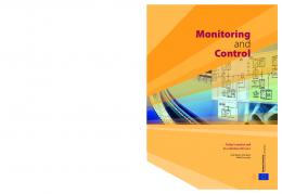
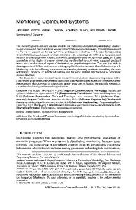
The current RFID-based distrusted manufacturing control system for the FMS contains the following components: 1. 30 RFID Active tags (FC909T active RFID tags).Each tag is attached to a component. 2. An RFID gate for each station which holds antenna, RFID reader, and manipulator. •Antenna (Motorola's AN480) which is installed on front of each station for sensing the parts •RFID reader (Motorola FX7400). Each reader is installed near to station’s IPC •Manipulator- which is used for preventing components on the conveyor from loading/ unloading process at the stations. 3. 3 IPC (PC/Microsoft Windows XP), which runs on the station control software and by which piece state data is received from the reader and stored in the database, and RFID gate is controlled. 4. HMI (PC/Microsoft Windows XP), which is used for monitoring the real time state of the productions. 5. Data server, application server and web server (2 PC/windows XP). The hardware architecture of our system is depicted in figure1. Figure 2 shows Machining station’s RFID gate.
PHYSICAL SYSTEM DESCRIPTION
FMS laboratory of Eastern Mediterranean University (EMU) was designed for education and research purposes. The laboratory consists of three stations: Station 1 is a machine tending station, which consists of a CNC milling machine and a five-axis vertically articulated robot (SCORBOT - ER 9) designed to work in industrial training facilities. Station 2 is an assembly and quality control station, which has one “SCORA ER 14” Robot provided by “Intelitek”. This robot has a pneumatic gripper and works in connection with the peripheral station devices such as a ball feeder, gluing machine and laser-scan micrometer device (Mitutoyo). Station 3 is an automatic storage and retrieval system (AS/RS), which contains 36 cells for storage and retrieval and a robot with the capability of taking and placing the work pieces. A conveyer integrates the stations for performing material handling within the cell. The robots with multi-tasking controllers provides real-time control and synchronization of up to 12 axes, 16 inputs and 16
499
Fig.2. Machining stattion’s RFID gate
The proposed multi-agent system m is designed as a network of software agents which interact wiith each other and the system actors. These agents categorized as; a Shop Management Agent, Agent Manger, Shop Monitorring and Command Agent, Station Control Agents, Station n Monitoring Agents, Agent Machine Interface and, Manufaacturing Resource Agent. In addition to the exist agents at thee architecture, two groups of database exist on the architecturee, shop database and station’s database. Furthermore, ontology (capability-based knowledge model) is required for multii-agent system for proper communication between the ageents. The ontology which is used for this work is developeed based [11]attempts. The architecture is designed to integ grate all the software agents with databases as well as onto ology. The shop multi-agent system architecture and its hardware h configuration are illustrated in figure 3. Next, thee functionalities of the main software agents in the propossed multi-agent system are described as follows:
Fig.1. RFID-enabled control architecture for the flexible manufacturing system
IV.
MULTI-AGENT SYSTEM ARCHITE ECTURE
Based on the physical compounds and connections of the RFID-enabled distributed control system identified in Section 4, multi-agent system is chosen to develop the application for realizing distributed control and monitoring system at the shop. It aims to implement, the RFID-enablled distributed control and monitoring system for the muultidisciplinary stations or facilities which are involved onn the product capability list. In this section, we present an ovverview of the multi-agent system architecture firstly, and then we will explain each all the agents as well as engineerring tools exist on the proposed architecture.
Fig.3. Multi-agent system architecture
500
Shop management Agent, is responsible of assisting a shop manager to define a new product for the system, specify the initial manufacturing parameters, decompose product capability for the system. It has a user interface for assisting the shop manager for making necessary changes while the plan gets more detailed and the higher levels of the plan need to be updated. This agent is also responsible to send the generated product capability list to the AS/RS’s RFID gate for writing the information on a desired piece’s tag. This agent linked with DELMIA engineering software to perform key manufacturing tasks. Agent Manager is responsible for controlling the utilization and availability of all agents by maintaining an accurate, complete and timely list of all active agents through which agents residing in the system are capable of cooperating and communicating with each other. Shop Monitoring and Command Agent is responsible of obtaining and displaying the real-time state of raw materials, in-process products, and finished products as well as the status of the stations. Also it serves to act as a port for incoming commands form the shop supervisor manually in case of any ad hoc events and new product setup. Station Control Agent, the station control agent realizes the process of selecting suitable capabilities from the product capability list for the station, and requesting capabilities from basic agents to do a job. Also, station control agent can update state data regularly at the station’s database, and can send control instructions to shop database. Station Monitoring Agent, the information reflecting manufacturing state in station is displayed by the station monitoring agent a history of the station’s process is stored in the station database. Manufacturing Resource Agent, represent specific manufacturing components, such as robots, conveyors, machinery, etc. that are identified to encapsulate all the capabilities, interaction behaviors (collective capabilities), and internal status that characterize these type physical components. Agent-Machine Interface is the agent that is directly connected to the physical controller. It acts as a kind of device driver to the Manufacturing resource agent. For each different controller there should be one agent machine interface. All the agents are connected by a local network (LAN) via which they communicate with each other through asynchronous message passing. For the expediency of the Shop Management Agent and the Agent Manager run on an application server; the Ontology operates on data server which is also responsible for maintaining the shop database, the Station Control Agent, Station Monitoring Agent, Manufacturing Resource Agent, the Agent Machine Interface additionally station’s database operate on the station’s IPC.
V.
STATION CONTROL AGENT
Although various multi-agent systems have been developed in the domain of distributed control system for FMS, station control as a base component for RFID-based distributed control systems has yet to be formally specified, implemented, integrated, and tested. Figure 4 illustrates the architecture of the “Station Control Agent” and its interactions with “Agent Machine Interface” and other engineering tools and agents. The station control agent is a kind of semiautonomous and service-oriented agent. The station control agent lunches when a tag (piece) is place on the station’s RFID gate. Detail processes are described below: Step 1: Each tag holds the product capability list which is written to the active tag at AS/RS‘s RFID gate, based on information from shop database. Step 2: The product capability list is loaded in “Station Control Agent” from the RFID gate. The SCA receives this information through the “Reader Middleware Agent” and send to the complex skill unit. Step 3: The “complex skill” unit verifies the received product capability list with the capabilities which are realizable on the station and decides to do any further action or not. The station’s capability list is available at “Station database”. Step 4: If the piece is the station’s desired: the “Complex Skill” unit will select appropriate capabilities from the product capability list. Step 5: The “Complex skill” unit with the assist of knowledge model (ontology) for each capability assigns: the information related to manufacturing resources and processes as well as the strategy about effectively and efficiently use of these resources and processes. Step 6: The “Control System” unit requests relevant services from the “Manufacturing Resource Agent”, if the MRA accept services the “Control System” stores the manufacturing resource information on the station database. Step7: the “Control System” unit sends appropriate command through the “Agent machine interface” to the “Manufacturing Resource Agent” for doing specific job (as an example: station’s robot take the compound from the conveyer and puts on the CNC milling machine table and start to milling process on the component). Step8: As soon as the job started on the station, the “Manufacturing Resource Agent” sends feed back to the “Control System” unit through the “Agent Machine Interface”. Once the “Control System” unit receives the feedback from the manufacturing resources controllers, the “Control System” sends this information to the “Station Monitoring Agent” for reflecting manufacturing process and storing on the station database. Step 9: Meanwhile, the manufacturing process of the desired component finished, the “Station Monitoring Agent” sends the
501
history of the component state to the shop databbase. In case of any constraint conflicts on the station, the staation controller sends back related feed back to the “Station C Control Agent” for further decisions and re-configuration.
Interaction-The cooperation betw ween all the agents implies a robust interaction schema that su upports information exchange and deals with error situation ns to avoid deadlocks and abnormal stopping situations. All the agents that are developed with C# codes are intteracted with Microsoft SQL Server (e.g. station database, Ontology) O by the SQL DB Provider component. Also thesee agents are interacted with “Shop Monitoring Agent” by Shell Shockwave ActiveX component. Furthermore for creaating connection between the “Station Control Agent” and HMI H using RS232 port the System IO Ports component is used. The UML sequence diagram in figure f 5 illustrates the Robot control agent interactions with th he other agents. A shot screen of the developed shop monitoring g system is depicted at figure 6. VII.
The study has discussed the multti-agent architecture proposed to support the design and implem mentation of an RFID-enabled distributed control and monitoring system for a manufacturing shop. The agents that compose the architecture have been conceived to cover flexibility, agility a and re-configurability posed by all the distributed “Station Control Agent”. The proposed multi-agent architecture contains different groups of agents at shop and staations level as well as some engineering tools can be used to support working mechanism of each group agents (station dataabase) or negotiation between them (ontology). Since, the “S Station Control Agent” and “Manufacturing Resource Agent”” are the kernel agents for the RFID-enable distributed control and monitoring system, the internal working mechanism off these agents explored and explained in detail and the interractions of these agents with the others are highlighted. For im mplementation, the hardware configuration of the system based on the multi-agent architecture is developed and used u different programming language as well as software all a the software agents and engineering tools are under imp plementation at FMS lab of Easter Mediterranean University.
Fig.4. “Station Control Agent” and its interactions with othher agents on the system
VI.
CONC CLUSION
IMPLEMENTATION
Agents and engineering tools-The system wass implemented using C# and the .Net framework. The .NET F Framework is a runtime execution environment that manages appplications that target the .NET Framework. It consists off the common language runtime, which provides memory maanagement and other system services, and an extensive class library, which enables programmers to take advantage of robust, reliable code for all major areas of application developm ment. Microsoft SQL Server database managemeent system is employed for development of the shop and statiions databases. In addition, for transferring logical UML models in to physical database (SQL Server) on ontologyy development .NET developer is used. This ontology devvelopment tool provides a user-friendly environment to creaate and update ontologies since it is possible to integrate an SQL database project file with an ordinary C# programs. ware Agent” are The source codes for the used Reader “Middlew available at the producer’s website () where the C# .NET codes is selected for current work. All coddes for “Shop Management Agent”, “Agent Manager”, “Sttation Control Agent” and, “Manufacturing Resource Agentt” applications were developed on C#. While, “Shop Monitorinng Agent” was established by SWISH Max 4 software using C programming language. The “Station monitoring Agent” whicch is placed on HMI is developed by PM designer 2.0 softwarre using Macro Language. The “Agent Machine Interface” whicch is placed on HMI is developed by PM Designer V1.2 using Macro Language.
Fig.5.Interaction of the Robot R Control Agent
502
[7] Liu, W. N., et al. "RFID-enabled real-time production motorcycle assembly management system for Loncin line." International Journal of o Computer Integrated Manufacturing 25.1 (2012): 86-99.
[8] Jun, H-B., et al. "A framework for f RFID applications in product lifecycle management." Internationall Journal of Computer Integrated Manufacturing 22.7 (2009): 595-615 [9] Yingfeng Zhang, T. Qu, Oscarr K. Ho and George Q. Huang, "Agent-based Smart Gateway for RFID-enabled R real-time wireless manufacturing," International Journal of Production Research, pp. 1337-1352, 2010b. [10] Dai, Qingyun, et al. "Radio frequency f identification-enabled real-time manufacturing execution system: a case study in an automotive part manufacturer." Inteernational Journal of Computer Integrated Manufacturing 25.1 (2012): 51-65 [11] Guerra-Zubiaga, David A., and Robert IM Young. "Design of a nternational Journal of Computer manufacturing knowledge model." In Integrated Manufacturing21.5 (2008)): 526-539. [12]Finkenzeller, Klaus. RFID Handbook: Radio-frequency pplications. New York: Wiley, identification fundamentals and ap 1999. [13]Krothapalli, Naga K. C., and Ab bhijit V. Deshmukh. "Design of negotiation protocols for multi-agent manufacturing systems." International Journal of Prroduction Research 37.7 (1999): 1601-1624. [14] Giret, Adriana, and Vicente Bottti. "From system requirements to holonic manufacturing system anaalysis." International journal of production research44.18-19 (2006): 3917-3928. [15]Weng, M. X., et al. "Multi-agent-based workload control for make-to-order manufacturing." Interrnational Journal of Production Research 46.8 (2008): 2197-2213. [16]Bellifemine, Fabio Luigi, Giovanni Caire, and Dominic Greenwood. Developing multi-agentt systems with JADE. Vol. 7. Wiley. com, 2007. [17] Shafiq, M. Omair, Ying Ding g, and Dieter Fensel. "Bridging multi agent systems and web serrvices: towards interoperability between software agents and sem mantic web services." Enterprise Distributed Object Computing Con nference, 2006. EDOC'06. 10th IEEE International. IEEE, 2006. [18] Tapia, Dante I., et al. "FUSIO ON@, a SOA-based multi-agent architecture."International Symposiu um on Distributed Computing and Artificial Intelligence 2008 (DCAI ( 2008). Springer Berlin Heidelberg, 2009. [19] Pétin, Jean-François, David Gouyon, and Gérard Morel. uct-driven automation and its "Supervisory synthesis for produ application to a flexible assemb bly cell."Control Engineering Practice 15.5 (2007): 595-614.
Fig.6. shop monitoring system
REFERENCES [1] Barenji,V,Ali, Barenji,V,Reza and Majid Hashemipour. "Structural Modeling of a RFID-enabled Reconfiguraable Architecture for a Flexible Manufacturing System." ITG-Faachbericht-Smart SysTech 2013 (2013). [2] Sikora, Riyaz, and Michael J. Shaw. "A multi-aagent framework for the coordination and integration of information systems." Management Science44.11-Part-2 (1998): S S65-S78. [3] Liu, Michael R., et al. "An RFID-based distributed control system for mass customization manufacturing." Parallel and Distributed Processing and Applications. Springer Berlin Heeidelberg, 2005. 1039-1049. [4]Satoh, Ichiro. "Location-based services in ubiquiitous computing environments."International Journal on Digital Libraaries 6.3 (2006): 280-291. [5] Barenji,V, Reza, Majid Hashemipour, and Daavid A. GuerraZubiaga. "Toward a Modeling Framework for Organizational Competency." Technological Innovation for the Inteernet of Things. Springer Berlin Heidelberg, 2013. 142-151. [6] Zhang, Yingfeng, et al. "Agent-based smart objeects management system for real-time ubiquitous manufacturing." Robotics and Computer-Integrated Manufacturing 27.3 (2011): 5388-549.
503