Automated localization of a camera network. Nadeem Anjum and Andrea Cavallaro. Queen Mary University of London. Mile End Road, E1 4NS London, UK.
IEEE INTELLIGENT SYSTEMS
1
Automated localization of a camera network Nadeem Anjum and Andrea Cavallaro Queen Mary University of London Mile End Road, E1 4NS London, UK {nadeem.anjum, andrea.cavallaro}@elec.qmul.ac.uk
Abstract—We present an algorithm for the automated external calibration (localization) of a network of cameras with nonoverlapping fields of view, a type of network that is becoming widespread for monitoring large environments. The proposed algorithm exploits trajectory observations in each view and works iteratively on camera-pairs. First outliers are identified and removed from each camera observations. Next, spatio-temporal information derived from the available trajectory is used to estimate unobserved trajectory segments in areas uncovered by the cameras. The unobserved trajectory estimates are used to estimate the relative position of each camera-pair, whereas the exit-entrance direction of each object is used to estimate their relative orientation. The process continues and iteratively approximates the configuration of all cameras with respect to each other. Finally, we refine the initial configuration estimates with bundle adjustment, based on the observed and estimated trajectory segments. The accuracy and the robustness of the proposed approach are demonstrated using both simulated and real datasets, and compared with state-of-the-art approaches.
I. I NTRODUCTION The deployment of camera networks is essential for the observation of large environments in applications such as traffic and behavior monitoring, remote surveillance and sporting events [1]. These networks are characterized by the presence of cameras with non-overlapping fields of view. Prior to applying video analytics in a camera network, internal as well as external calibration of each camera of the network has to be performed [2]. This calibration helps in solving camera hand-overs of targets and reconstructing complete trajectories from partial views [3]. External calibration (also referred to as localization) provides information about the relative position and orientation of a camera with respect to the rest of the network. When the number of cameras is large, it is impractical to employ manual localization techniques. Moreover, the use of GPS-based methods might not be viable all the time, as they are more expensive and there are scenarios when they are not suitable at all (e.g., when monitoring an underground train station). There is therefore the need for an automatic camera localization approach that can exploit the information observed in each camera view. A. Prior work Existing localization approaches for non-overlapping cameras primarily assume that objects (e.g., pedestrians or vehicles) move linearly in unobserved regions [4]. Under this assumption, the relative position of two cameras can be estimated by extrapolating the trajectory in unobserved regions using the velocity information learnt from the last
few observed instances. To estimate the relative orientation of two cameras, vanishing points [5] or far objects with known trajectories (e.g., stars) can be used [6]. There exists various approaches that learn the topology of non-overlapping camera networks using graph representation [7]. In these approaches, camera nodes are considered as vertices and their spatial neighborhood as edges of a graph. The performance of these approaches degrades substantially when the dynamics of the camera network is complex and also when the object motion deviates considerably from the pre-modeled path in unobserved regions [8]. Other approaches track an object while simultaneously estimating the network localization parameters [9]. A Bayesian framework can be used to find unknown parameters (localization and trajectory), given the observations from each camera. Maximum a posterior (MAP) is estimated using the Newton-Raphson method that makes the method computationally expensive with increasing number of cameras and length of the trajectory. Furthermore, the performance degrades substantially with noisy observations. In order to address these problems, it is desirable to first estimate trajectory segments in unobserved regions and then to learn the localization parameters based on both observed and estimated trajectory segments [10]. B. Our contributions In this paper, we present an automated localization algorithm that uses trajectories to estimate the configuration of a camera network and is also applicable when cameras have nonoverlapping fields of view. The algorithm initially removes outliers from the observations of each camera view. Next, unlike other approaches [4], [7], [9], it iteratively uses spatiotemporal information derived from the available trajectory information to estimate the unobserved trajectory segment that is then used to position the cameras on a common plane. The exit-entrance direction of the object is used to estimate the relative orientation of the cameras. After this initial estimation, the configuration results are refined using bundle adjustment. Our major contributions are: (a) the relaxation of the linearity constraint on the object motion in unobserved regions (the object can take a sharp turn); (b) no prior information about the environment or the motion model is required; and (c) the initial configuration of the network can be approximated using local pairwise processing followed by refined results achieved offline when batch processing is viable. The paper is organized as follows. Sec. II formalizes the problem and presents the proposed approach. Sec. III discusses the results. Finally, Sec. IV draws the conclusions.
IEEE INTELLIGENT SYSTEMS
2
ck
ck
o
cj
rk
ci
yk
o
cj ci
rj yj
o yi
m = m0 + τ
m = m0
ri
(0,0) x i
Fig. 2. Example of formation of a camera-pair (ci and cj ): an object exits from ci at m=m0 and enters into the field of view of cj at m=m0+τ without being observed by another camera.
xj xk
Fig. 1. Illustration of the unknown localization parameters for the definition of the configuration of the camera network. The center of each camera ci is shown by a circle; (xi , yi ) is the position of ci and ri is the orientation of ci with reference to the horizontal axis.
II. P ROPOSED APPROACH A. Problem Formulation Let C = {c1 , c2 , ..., cN } be a network of N cameras and z m = (xm , y m ) the position of a moving object within the field of view1 of camera ci at time instant m. Let each camera provide a vertical top-down view of a portion of the scene, either because its optical axis is perpendicular to the ground plane or because its view is normalized. Under this assumption, the parameters for localizing camera ci are its position, (xi , yi ), and its rotation angle, ri , about its optical axis, measured with respect to the horizontal axis of the ground plane. The set L of unknowns (Fig. 1) is therefore L = {(x1 , y1 , r1 ), (x2 , y2 , r2 ), ..., (xN , yN , rN )}.
(1)
Moreover, let us define camera ci and camera cj as a camera-pair i.e., when an object exits the field of view of ci and enters the field of view of cj , where j 6= i, without being observed by another camera. Note that, according to this definition, ci and cj may become a camera-pair, even if ci and cj are not physically close to each other (Fig. 2). The flow diagram of the proposed approach for an iteration is shown in Fig. 3. The details of algorithmic steps for the entire network are provided in Algo. 1 and described in the following sections.
data which are consistent with the assumed model. This makes RANSAC able also to filter out noisy observations that are unrelated to the instantaneous function of the object state (beyond the measurement error). Let the motion parameters be approximated with a polynomial of degree l. We start with nb observations chosen randomly from a trajectory segment. Next, within this subset, we find the observations that are within a given tolerance of the polynomial model. We repeat the process until the number of observations within this tolerance is more than 50% of the total number of observations of that trajectory segment in the camera view. The observations that fall outside the region of tolerance are considered outliers and therefore discarded from further processing. Once the trajectories are filtered within the field of view of a camera, they are used to estimate the movement of the object in the unobserved regions, as described in the next section. C. Trajectory estimation In order to generate the complete trajectory Z 0 = {z 0 , ..., z m0 , zˆm0 +1 , ..., zˆm0 +τ −1 , z m0 +τ , ..., z m0 +τ +m1 } (2) of the moving object, we use the spatio-temporal information derived from available trajectory segments Z = {z 0 , ..., z m0 , z m0 +τ , ..., z m0 +τ +m1 }
in the fields of view of the cameras in order to estimate the trajectory points in the unobserved regions Zˆ = {ˆ z m0 +1 , ..., zˆm0 +τ −1 }.
B. Pre-processing The observations in field of view of each camera (trajectory segments) are first pre-processed to remove outliers. As the trajectory segment can be corrupted by various types of estimation noises, we use RANSAC to smooth it before further processing. Instead of using all the available data, RANSAC starts with a small subset of the complete data and then adds 1 For clarity of notation we do not use the subscript i for the position of an object within camera ci .
(3)
(4)
The estimation of the trajectories in the unobserved region between ci and cj is performed in three steps: (i) forward and backward estimations, (ii) Kalman filtering and (iii) fusion. First, we estimate the sequence of positions from time instant m0 , corresponding to the last observation in ci , to m0 + τ , corresponding to the first observation in cj . This estimation is performed in the forward and backward directions. The forward estimation generates the series of candidate positions Z˜f = {˜ zfm0 +1 , ..., z˜fm0 +τ −1 };
(5)
IEEE INTELLIGENT SYSTEMS
3
Z
ci
preprocessing
forward motion model
~
Zf
modified Kalman filter
^
Zf ^
fusion preprocessing
backward motion model
cj Fig. 3.
~
Zb Z
modified Kalman filter
Z
t L ttrajectory j t Z' parameter estimation reconstruction
^
Zb
Iteration of the parameter estimation for a camera-pair.
whereas the backward estimation generates the series of candidate positions Z˜b =
{˜ zbm0 +1 , ..., z˜bm0 +τ −1 }.
(6)
z˜fm+1 =(˜ xm+1 , y˜fm+1 ) f
be generated by
Let each observation a forward motion model as m+1 x ˜f 1 m+1 x ˜ 0 ν,f m+1 y˜ = 0 f m+1 0 y˜ν,f
ax,f 1 0 0
m m x ˜f vx 0 0 m m x ˜ v 0 0 , + ν,x ν,f m 1 ay,f y˜f vym m m 0 1 vν,v y˜ν,f
(7)
m where (˜ xm ˜ν,f ) is the velocity of the object. Furν,f , y thermore, ax,f and ay,f are computed independently for each available trajectory segment using the lth order polynomial fitting on observations from ci . Moreover, vm (N (0, Σm v )) is modeling additive noise with covariance −3 Σm =diag([1e , 1e−3 , 1e−3 , 1e−3 ]). v Similarly, let each observation z˜bm =(˜ xm ˜bm ) be generated b ,y by a backward motion model as m+1 m+1 m x ˜b x ˜b vx 1 ax,b 0 0 m+1 m m+1 vν,x x 0 x ˜ ˜ 1 0 0 ν,b ν,b m+1 + m+1 , (8) m= y˜b 0 vy 0 1 ay,b y˜b m m+1 m+1 0 0 0 1 y˜ν,b vν,v y˜ν,b
where ax,b and ay,b are calculated like ax,f and ay,f , but using the observations from cj . Before fusing the forward and backward estimated trajectories, we filter them using a modified Kalman filtering to obtain smoothed estimated positions, i.e., Zˆ = {ˆ z m0 +1 , ..., zˆm0 +τ −1 }. The Kalman gain, k m , is calculated as k m = Σvm−1 A[AT Σvm−1 A + Σwm ]−1 , (9) where Σwm is the covariance of the observation noise at instant m and A maps the state vector with the measurements. The object position is updated using a forward motion model as zˆfm+1 = zˆfm + k m (˜ zbm − A(ˆ zfm )). z˜bm
(10) z˜bm
Note that is used to calculate the residual − A(ˆ zfm ), which is the discrepancy between the forward estimation and the backward estimation. Zero residual means that the forward and the backward measurements are in agreement. This modification ensures that the object will be in the correct state at m0 + τ , in accordance with the observation in cj .
Algorithm 1 Automated localization of a camera network. Variables: IDt : ID of the camera observing the target at t I, J: IDs of the first and second cameras in a camera-pair ζ: overall change in camera positions δ: minimal change threshold κ: iteration number Initializations t=1; ζ = Inf; κ = 0 1: while ζ ≥ δ do 2: increment κ % start iterations 3: I = IDt−1 4: while I == IDt do , yIt−1 ) 5: zIt−1 = (xt−1 I 6: m0 = t-1 7: increment t 8: end while 9: if target is unobserved then 10: increment t 11: else 12: J = IDt 13: m0+τ = t 14: increment t 15: while J == IDt do , yJt−1 ) 16: zJt−1 = (xt−1 J 17: m0+τ +m1 = t-1 18: increment t 19: end while 20: apply RANSAC on Z (Sec. II.B) 21: compute Z˜f and Z˜b using Eq.(7) and Eq.(8), respectively 22: compute Zˆf and Zˆb using Eq.(10) and Eq.(11), respectively 23: compute Zˆ using Eq.(12) κ 24: compute DI,J using Eq.(13) κ 25: compute rI,J using Eq.(18) 26: pκI = (xI , yI ) κ 27: pκJ = (xJ , yJ )+DI,J κ κ κ κ 28: LI,J ← (pI , pJ , rI,J ) 29: t=m P0+τ κ κ−1 30: ζ = N ) n=1 N orm2 (pn , pn 31: end if 32: end while % end iterations 33: compute L∗ using Eq.(19) % non-iterative refinements
Similarly, the object position is updated using the backward motion model as zˆbm+1 = zˆbm + k m (˜ zfm − A(ˆ zbm )). z˜fm − A(ˆ zbm ),
z˜fm
(11)
Again, in the residual term is used to ensure that the estimated object state at instant m0 is in accordance with the observation in ci .
IEEE INTELLIGENT SYSTEMS
4
True trajectory Observations Forward only Backward only Estimated trajectory
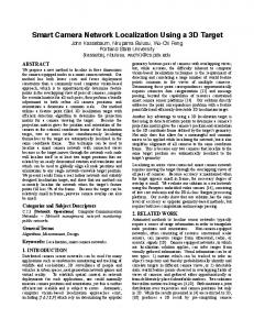
Fig. 4. Trajectory estimation with and without Kalman corrections (Key. gray: two non-overlapping cameras; blue circles: observations in each camera (Z); red line: the true trajectory; black dots: forward estimation ˜f ); magenta line-dots: backward estimation (Z ˜b ); green line: estimated (Z ˆ trajectory (Z).)
The filtered forward and backward estimated segments are finally fused as: zˆm = (1 − β m )ˆ zfm + β m zˆbm ,
(12)
where β m = m/m0 + τ for m = 1, ..., m0 + τ . The forward estimations get higher weights when the object is closer to ci and these weights are progressively reduced when the object moves away from ci . Figure 4 shows a trajectory estimation comparison with and without Kalman filtering corrections. Without the corrections, both the forward and the backward estimates end far from the real object position in the fields of view of the cameras. Kalman filtering followed by fusion improves the estimation of the object position (green). D. Position and orientation estimation To localize the cameras we need to calculate their relative position (the distance between their centers) and their relative orientation. To estimate the relative position of cj with respect to ci , we use the displacement vector, Dij , calculated as Dij = z m0 − zˆm0 +τ .
(13)
Furthermore, to estimate the relative orientation rˆij of the camera-pair, we could calculate the angle between the observed object position z m0 +τ and the corresponding estimated object position zˆm0 +τ in camera cj as rˆij = cos−1
(xm0 +τ , y m0 +τ ).(ˆ xm0 +τ , yˆm0 +τ ) . m +τ m +τ |(x 0 , y 0 )||(ˆ xm0 +τ , yˆm0 +τ )|
(14)
y m0 +τ +q − y m0 +τ +q−1 , xm0 +τ +q − xm0 +τ +q−1
changes its direction considerably, we use � m0 + τ + q if |α(q) − α(q + 1)| > ξ ms = . m0 + τ + m1 otherwise (16) Equation 16 explains that if the change in object direction is significant (ξ = π/12) at m0 +τ +q within the field of view of cj , then we consider the trajectory segment only to that point for estimating the relative orientation; otherwise, the complete trajectory segment is used. To generate an estimated sequence Zˆ s = {ˆ z m0 +τ , ..., zˆms },
(15)
where q = 1, ..., m1 and m1 is the number of consecutive observations in cj . To find the time ms at which the object
(17)
we extrapolate further the trajectory estimate from instant m+ τ to ms . We rotate the observed segments with θ = −π + π n. 180 where n = 0, 1, ..., 360. The final relative orientation, rij , between ci and cj is calculated as rij = arg min D(Zˆ s , Vθ (Z s )),
However, to increase the robustness of the orientation estimation process, instead of relying on single instances of observation and estimation, we use a sub-segment of the available trajectory segment in cj . This sub-segment is extracted using the directional angle α(.), calculated as α(q) = tan−1
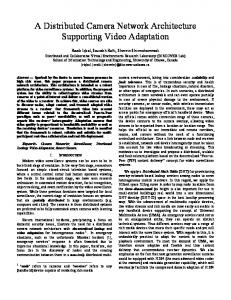
Fig. 5. An example of improvements of the estimation results using bundle adjustment: (top) input dataset and (bottom) localization of each camera, where the estimation before (blue) and after (green and * with each camera ID) bundle adjustments are superimposed.
(18)
θ
where Vθ (.) rotates Z s at an angle θ and D(., .) calculates the L2 distance between the estimated and (rotated) observed trajectory segments. The process of estimating the relative position and orientation continues and iteratively approximates the configuration of all cameras with respect to each other. The process terminates when the total change in position estimation is smaller than a pre-defined threshold, δ, for example δ = 1% of the area representing the field of view of a camera.
IEEE INTELLIGENT SYSTEMS
5
5 4
3
2
6 1
(a)
(b)
(c)
(e)
(f)
4
7
6
3 5
8
2
1
(d)
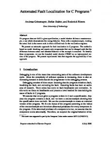
Fig. 6. Examples of camera network localization on simulated datasets: (a,d) trajectory of an object (black line) and field of view of each camera (gray) (Copyright 2010 Google - Map data); (b,e) localization results of MAP (orange) and MMAP (red) superimposed on the true camera configuration; (c,f) localization results of PBBA (dark-blue) and PABA (light-blue) superimposed on the true camera configuration. c1 (black) is the reference camera.
Finally, we can refine the localization results, L = {(p1 , r1 ), (p2 , r2 ), ..., (pN , rN )} with pi =(xi , yi ), by employing bundle adjustment. The cost function for bundle adjustment is defined to ensure that the localization parameters allow for the minimal difference between observations and estimates: L∗ = argmin L
N X
||Zi − ri (pi + Zˆi )||2 ,
(19)
i=1
where Zi and Zˆi are sets of observed and estimated positions in ci . Figure 5 shows an example of refinements with bundle adjustment. Figure 5(top) shows the true camera configuration of the network along with the object trajectory. Figure 5(bottom) shows the initial configuration results (blue) that are refined after applying bundle adjustment (green). Significant improvements can be observed in the relative positioning of c3 , c4 , c7 and c8 . Additional results and the evaluation of the proposed approach are discussed in the next section.
erated from five cameras (Fig. 7). The simulated trajectories are grouped in two datasets consisting of six cameras and eight cameras, respectively. In the real dataset, a toy car moves across the network on a car track that is rotated during video acquisition to increase the variability of the trajectory. We use change detection to extract and to generate the trajectory. The coverage area is approximately 4.40 sq. meters. The dataset consists of 19137 frames. We compare the results of the proposed approach before bundle adjustment (PBBA) and after bundle adjustment (PABA) with a state-of-the-art MAP-based approach [9]. Additionally, we initialize the MAP-based approach with the initial configuration estimated by the proposed approach (PBBA) and refer to it as Modified MAP (MMAP). The algorithms are developed in Matlab (ver 7.5) and run on a Pentium (R) dual core CPU @ 2.00 GHz with 3.0 GB memory. B. Discussion
III. E XPERIMENTAL RESULTS A. Experimental setup We evaluate the proposed approach and compare it with state-of-the-art algorithms on simulated trajectories with varying levels of complexity (Fig. 6) and on a real dataset gen-
Figure 6(a,d) shows the true camera configurations of two simulated camera networks. For both sequences, c1 is the reference camera (black). Figure 6(b,e) shows the localization result using MAP (orange) superimposed on the true camera configuration. The results show that there are considerable
IEEE INTELLIGENT SYSTEMS
6
TABLE I E VALUATION OF THE ACCURACY OF THE ALGORITHMS UNDER ANALYSIS ON THE SIMULATED DATASETS . S
1
2
Algo. �t MAP �r � MMAP t �r �t PBBA �r �t PABA �r �t MAP �r � MMAP t �r �t PBBA �r �t PABA �r
c2 20.86 25.00 24.14 10.00 2.01 10.00 0.25 5.00 20.02 20.00 23.83 0.00 2.26 10.00 0.61 0.00
c3 19.83 16.00 18.50 15.00 1.12 15.00 0.34 5.00 27.45 20.00 29.97 10.00 0.82 8.00 0.17 2.00
c4 14.58 16.00 11.79 15.00 1.24 10.00 0.12 4.00 21.11 4.00 20.52 2.00 0.14 2.00 0.21 1.00
c5 11.52 10.00 11.00 5.00 0.54 5.00 0.06 0.00 18.16 10.00 17.61 6.00 0.03 4.00 0.21 0.00
c6 3.46 10.00 2.70 2.00 0.51 0.00 0.16 0.00 14.62 18.00 14.44 13.00 0.61 12.00 0.34 9.00
c7 4.74 21.00 4.16 16.00 2.29 15.00 0.40 10.00
c8 6.99 20.00 5.84 10.00 0.38 4.00 0.61 3.00
Avg. 14.05 15.40 13.63 9.40 1.08 8.00 0.18 2.80 16.16 16.14 16.62 8.14 0.93 7.86 0.36 3.57
TABLE III E VALUATION OF THE ACCURACY AND ROBUSTNESS TO CAMERA FAILURE OF THE ALGORITHMS UNDER ANALYSIS ON THE REAL DATASET. Desc.
Algo. MAP MMAP
All cameras PBBA PABA MAP MMAP c2 fails PBBA PABA MAP
TABLE II C OMPARISON OF PROCESSING TIME FOR MAP, MMAP, PBBA AND PABA WHEN VARYING THE NUMBER OF UNKNOWN PARAMETERS
MMAP c3 fails
( CAMERA LOCALIZATION PARAMETERS AND MISSING OBSERVATIONS ). S 1 2
No. of param 18+1187 24+2118
MAP 310.11 563.05
MMAP 280.39 401.73
PBBA 120.12 155.71
PBBA PABA
PABA 173.06 221.10
MAP MMAP c4 fails
errors in approximating the cameras’ positions. Specifically, in the first sequence, c2 , c3 and c4 are noticeably misplaced. Similarly, for the second sequence, c2 , c3 and c7 are far from the true camera configuration. This is primarily because MAP can handle only subtle turns in the unobserved regions. The localization results for MAP are improved when it is initialized with the output of PBBA. On the other hand, Figure 6(c,f) shows the results of the proposed approach, where the initial results (dark-blue) are improved by employing bundle adjustment (light-blue). Table I summarizes the localization accuracy for MAP, MMAP, PBBA and PABA on the simulated datasets. The position estimation error, �t , is calculated with the L2 norm whereas the rotation error, �r , is calculated with the L1 norm. In the first sequence MAP has, on average, 13.87 size-units larger position estimation error compared to PABA. This error difference is reduced by 0.42 size-units with MMAP. In terms of rotation, MAP results in 12.60 deg. worse error than PABA. With MMAP this error difference is reduced to 6.6 deg. Similarly, for the second sequence, the average position estimation error for PABA is 0.36 size-units, which is 15.8 size-units smaller than that of MAP and 16.26 sizeunits smaller than MMAP. Table II compares MAP, MMAP, PBBA and PABA in terms of processing time. For the first dataset the number of unknown parameters is 1205 (12 for the camera positions, 6 for the camera orientations and 1187 for the missing observations) and for the second dataset the number of unknown parameters is 2118 (16 for the camera positions, 8 for the camera orientations and 2094 for missing observations). By increasing the number of unknown parameters from 1205 to 2118, the processing time for PABA is increased by 27.74% and the processing time for MAP is increased by 81.56%. With a
PBBA PABA
�t �r �t �r �t �r �t �r �t �r �t �r �t �r �t �r �t �r �t �r �t �r �t �r �t �r �t �r �t �r �t �r
c2 8.91 13.00 8.90 7.00 0.66 7.00 0.08 4.00 8.95 15.00 8.91 15.00 0.64 15.00 0.06 7.00 8.92 13.00 8.89 7.00 0.66 4.00 0.08 4.00
c3 12.76 17.00 13.04 11.00 1.82 11.00 0.79 3.00 9.36 25.00 10.24 18.00 0.27 15.00 0.14 14.00 12.76 17.00 13.04 11.00 1.82 11.00 0.79 3.00
c4 17.88 13.00 17.59 13.00 0.28 13.00 0.28 1.00 13.94 18.00 16.74 15.00 0.93 13.00 0.49 8.00 18.10 19.00 18.07 17.00 0.11 16.00 0.11 6.00 -
c5 27.34 5.00 26.98 5.00 0.30 4.00 0.28 1.00 26.15 12.00 26.43 10.00 1.12 9.00 0.50 7.00 26.15 12.00 26.43 10.00 1.11 9.00 0.49 7.00 27.15 5.00 27.15 5.00 0.35 5.00 0.21 2.00
Avg. 16.72 12.00 16.63 9.00 0.76 8.75 0.36 2.25 16.48 18.33 17.80 14.33 0.77 12.33 0.38 9.67 17.33 15.33 17.80 14.00 0.41 13.33 0.22 6.67 16.28 11.67 16.36 7.67 0.94 6.67 0.36 3.00
better initialization (i.e., MMAP) the processing time for MAP is increased by 43.02%, which is however still higher than PABA. This confirms that the proposed approach is less time consuming than MAP. This is an important aspect especially for the scalability of a network. Figure 7(c) illustrates the localization results of MAP, MMAP, PBBA and PABA on the real dataset. The corresponding localization errors are summarized in Table III. The average position estimation error for the proposed approach is 0.36 mm, while the average position estimation errors for MAP and MMAP are respectively 16.72 mm and 16.63 mm. Similarly, the average rotation error for PABA is 2.25 deg., which is 9.97 deg. smaller than MAP and 6.75 deg. smaller than MMAP. Furthermore, we also evaluate the robustness of the proposed algorithm to camera failure situations and compare it with MAP. To this end, we dropped all the observations from one camera at a time and applied the algorithms. The results are shown in Fig. 8. Table III summarizes the localization accuracy: c3 is the most important camera in the network as it contains most of the sharp turns taken by the object; therefore, in case of its failure the localization errors for the rest of network increases substantially; c4 is the least important camera. In fact, since the trajectory segments in c4 can be approximated with the observations of c2 , c3 and c5 , its failure does not affect considerably the performance of network localization.
IEEE INTELLIGENT SYSTEMS
7
c5 c4
y
c3
y
x x
c2
3 2 1
x
y
y
(a)
4
(b)
y
x
x
c1
5
(c)
Fig. 7. Localization results on a real dataset: (a) the experimental setup; (b) trajectory (line) superimposed on the true camera configuration (gray); (c) localization results using MAP (orange), MMAP (red), PBBA (dark-blue) and PABA (light-blue) superimposed on the true camera configuration (gray).
(a)
(b)
(c)
Fig. 8. Localization results in case of camera failure: MAP (orange), MMAP (red), PBBA (dark-blue) and PABA (light-blue) when (a) c2 fails; (b) c3 fails; and (c) c4 fails.
IV. C ONCLUSIONS We proposed an algorithm for the localization of a network of non-overlapping cameras that allows us to relax the traditional linearity or smooth-turn constraint on the motion of objects. The algorithm recovers the position and the orientation of each camera based on two main steps: the estimation of the unobserved trajectory in regions not covered by the cameras’ fields of view and the estimation of the relative orientations of the cameras. Kalman filtering is initially employed on the available trajectory segments to extrapolate their value in the unobserved regions, with the modification that the forward motion model provides measurements for the backward trajectory estimation and vice versa. This helps in improving the accuracy of the trajectory estimation in the unobserved regions. The relative orientation of the cameras is then obtained by using the estimated and the observed exit and entry point information in each camera field of view. The proposed approach can be applied using local pairwise processing (if a sub-optimal solution is acceptable) or offline, with a refinement based on bundle adjustment. The performance of the proposed approach was demonstrated using both simulated and real datasets. Our current work includes using other sensor modalities, such as audio [11], to improve the estimation of the trajectory segments in the unobserved regions on real data sequences. R EFERENCES [1] A. Dore and C. Regazzoni, “Interaction analysis with a bayesian trajectory model,” IEEE Intelligent Systems, vol. 25, no. 3, pp. 32–40, April 2010.
[2] D. Marinakis and G. Dudek, “Self-calibration of a vision-based sensor network,” Image and vision computing, vol. 27, no. 1-2, pp. 116–130, January 2009. [3] R. Pflugfelder and H. Bischof, “Localization and trajectory reconstruction in surveillance cameras with non-overlapping views,” IEEE Trans. on Pattern Analysis and Machine Intelligence, vol. 32, no. 4, pp. 709– 721, April 2010. [4] O. Javed, Z. Rasheed, O. Alatas, and M. Shah, “Knight: A real time surveillance system for multiple overlapping and non-overlapping cameras,” in Proc. of Int. Conf. on Multimedia and Expo, Baltimore, USA, July 2003. [5] I. N. Junejo, X. Cao, and H. Foroosh, “Autoconfiguration of a dynamic nonoverlapping camera network,” IEEE Trans. on Systems, Man and Cybernetics, Part B, vol. 37, pp. 803–816, August 2007. [6] R. B. Fisher, “Self-organization of randomly placed sensors,” in Proc. of Eur. Conf. on Computer Vision, Copenhagen, Denmark, May 2002. [7] D. Makris and J. Black, “Bridging the gaps between cameras,” in Proc. of Intl. Conf. on Computer Vision and Pattern Recognition, WashingtonDC, USA, June 2004. [8] D. Marinakis, G. Dudek, and D. J. Fleet, “Learning sensor network topology through monte-carlo expectation maximization,” in Proc. of Intl. Conf. on Robotics and Automation, Barcelona, Spain, April 2005. [9] A. Rahimi, B. Dunagan, and T. Darrell, “Simultaneous calibration and tracking with a network of non-overlapping sensors,” in Proc. of IEEE Conf. on Computer Vision and Pattern Recognition, Washington-DC, USA, July 2004. [10] N. Anjum, M. Taj, and A. Cavallaro, “Relative position estimation of non-overlapping cameras,” in Proc. of IEEE Int. Conf. on Acoustics, Speech, and Signal Processing (ICASSP), Honolulu, USA, April 2007. [11] H. Zhou, M. Taj, and A. Cavallaro, “Target detection and tracking with heterogeneous sensors,” IEEE Journal of Selected Topics In Signal Processing, vol. 2, no. 4, pp. 505–513, August 2008.