Rochester, New York. 1998 ... application to maximize locality and minimize communication. ... component granularity in the application to enable partitioning.
Automatic Distributed Partitioning of Component-Based Applications by
Galen C. Hunt
Submitted in Partial Fulfillment of the Requirements for the Degree Doctor of Philosophy
Supervised by Michael L. Scott
Department of Computer Science The College Arts and Sciences
University of Rochester Rochester, New York
1998
ii
To Lori, who has often wondered out loud if I cared about anything other than computers, but in her heart has always known that it is for her that my life goes on…
iii
Curriculum Vitae
Galen C. Hunt was born in St. George, Utah on December 27, 1968. He attended Dixie College receiving an Associate of Science degree in 1988. He completed his undergraduate studies in physics at the University of Utah, graduating with a Bachelor of Science degree in 1992. He came to the University of Rochester in the fall of 1994 and began graduate studies in Computer Science. In 1995, he received a fellowship from Microsoft Research. He pursued research in the automatic distributed partitioning of component-based applications under the direction of Professor Michael L. Scott and received a Master of Science degree in 1996 and a Doctor of Science degree in 1998.
iv
Acknowledgements
The Department of Computer Science at University of Rochester has been a wonderful place to study. It was here that I first realized that computer science is about more than just computers. It was here, under the direction of first Tom LeBlanc, and later Michael Scott that I began to understand and practice the science of computer science. Tom convinced me to come here, and Michael patiently guided me through the apprenticeship to earn my Ph.D. I am deeply indebted to each. David Albonesi and Sandhya Dwarkadas served patiently on my committee and provided valuable support. Acknowledgements also go to Rick Rashid of Microsoft Research, who helped me select a research topic full of more surprises and satisfaction than I could have ever imagined. Microsoft generously funded most of my graduate career at the University of Rochester. In return, Rick only asked for my unwavering allegiance. :-)
v
Abstract
Distributed applications provide access to distributed resources including memory, processor cycles, and I/O devices. It is easy to create distributed applications with poor performance, but difficult to create distributed applications with good performance. High-performance distributed applications are difficult to create in large part because the programmer must manually partition and distribute the application to maximize locality and minimize communication. This dissertation asserts that system software, not the programmer, should shoulder the burden of distribution. We identify the features necessary to automatically partition and distribute applications. These features include structural metadata to identify and isolate application components, support for component location transparency, dynamic metadata to quantify inter-component communication, an algorithm to choose a distribution, mechanisms to realize a chosen distribution, and sufficient component granularity in the application to enable partitioning. We demonstrate that a large class of applications can be distributed efficiently without access to source code using automatic partitioning tools that minimize distributed communication. This dissertation describes a functional system, Coign, that automatically distributes applications conforming to Microsoft Corporation's Component Object Model (COM).
Coign has been applied to several
commercial applications, including the Microsoft Picture It! image processor. To our knowledge, Coign is the first system to provide automatic distributed partitioning of binary applications.
vi
Contents Curriculum Vitae .......................................................................................................iii Acknowledgements..................................................................................................... iv Abstract........................................................................................................................ v List of Tables .............................................................................................................. ix List of Figures.............................................................................................................. x 1. Introduction............................................................................................................. 1 1.1. Problem Domain: Distributed Systems .........................................................................................3 1.1.1. Picture It!: A Distributed Scenario.........................................................................................4 1.1.2. Distributed Partitioning .................................................................................................. ........5 1.2. Solution Domain: COM ......................................................................................................... .......7 1.3. Thesis Statement ............................................................................................................ ...............8 1.4. Issues for Automatic Distributed Partitioning ...............................................................................9 1.4.1. Discovery: Understanding Application Behavior.................................................................10 1.4.2. Decision: Choosing a Distribution .......................................................................................12 1.4.3. Distribution: Creating the Distributed Application ..............................................................14 1.5. Dissertation Organization................................................................................................... .........15
2. Background and Related Work ........................................................................... 17 2.1. Automatic Distributed Partitioning .............................................................................................17 2.1.1. ICOPS ..................................................................................................................................19 2.1.2. CAGES.................................................................................................................................21 2.1.3. VisualAge Intelligent Dynamic Application Partitioning ....................................................22 2.1.4. Summary ..............................................................................................................................23 2.2. Component Systems ....................................................................................................................24 2.2.1. COM.....................................................................................................................................24 2.2.1.1. Interfaces .......................................................................................................................24 2.2.1.2. Binary Compatibility.....................................................................................................27 2.2.1.3. Location Transparency ..................................................................................................28 2.2.2. CORBA ................................................................................................................................29 2.2.3. Summary ..............................................................................................................................32 2.3. Distributed Systems.....................................................................................................................32 2.3.1. Distributed Communication Services...................................................................................32 2.3.1.1. Sockets ..........................................................................................................................33 2.3.1.2. RPC ...............................................................................................................................33 2.3.1.3. Java RMI .......................................................................................................................33 2.3.1.4. CORBA .........................................................................................................................34 2.3.1.5. Group Communication Services....................................................................................34 2.3.1.6. Summary .......................................................................................................................34 2.3.2. Distributed Operating Systems.............................................................................................35
vii
2.3.2.1. Emerald .........................................................................................................................35 2.3.2.2. SOS ...............................................................................................................................36 2.3.2.3. Clouds ...........................................................................................................................36 2.3.2.4. Argus .............................................................................................................................37 2.3.2.5. Sprite, Mach, and the V System ....................................................................................37 2.3.2.6. Amoeba .........................................................................................................................37 2.3.2.7. Inferno ...........................................................................................................................38 2.3.2.8. WebOS ..........................................................................................................................38 2.3.2.9. Summary .......................................................................................................................38 2.3.3. Large-Scale Distributed Object Systems..............................................................................39 2.3.3.1. Globe .............................................................................................................................39 2.3.3.2. Legion............................................................................................................................39 2.3.3.3. Summary .......................................................................................................................40 2.4. Parallel Partitioning and Scheduling ...........................................................................................40 2.5. Structural Application Analysis ..................................................................................................41 2.5.1. SANE ...................................................................................................................................41 2.5.2. Canfora et al. ........................................................................................................................42 2.5.3. OO!CARE .................................................................................................................. ..........42 2.5.4. Module-Level Cobol Dependence Graphs ...........................................................................42 2.5.5. Carmichael et al. ..................................................................................................................43 2.5.6. Summary .................................................................................................................. ............44 2.6. Conclusion................................................................................................................. ..................44
3. Issues in Automatic Distributed Partitioning..................................................... 46 3.1. Component Classification ...........................................................................................................47 3.1.1. The Problem .........................................................................................................................47 3.1.2. The Solution .........................................................................................................................51 3.1.3. Evaluation.............................................................................................................................52 3.1.4. Summary ..............................................................................................................................59 3.2. Network Communication ............................................................................................................59 3.2.1. Network Sampling................................................................................................................59 3.2.2. Compressing Communication Information ..........................................................................65 3.2.3. Summary ..............................................................................................................................68 3.3. Graph Cutting..............................................................................................................................68 3.3.1. Graph Cutting Algorithms....................................................................................................68 3.3.2. Mapping Distributed Partitioning onto Graph Cutting .........................................................71 3.3.3. Summary ..............................................................................................................................73 3.4. Conclusion...................................................................................................................................73
4. The Coign ADPS: Overview and Evaluation ..................................................... 74 4.1. A Guided Tour ............................................................................................................................74 4.1.1. Creating a Distributed Application.......................................................................................75 4.1.2. Discussion ............................................................................................................................82 4.2. Architecture.................................................................................................................................82 4.3. Evaluation ...................................................................................................................................86 4.3.1. Feasibility.............................................................................................................................87 4.3.2. Changing Scenarios and Distributions .................................................................................89 4.3.3. Performance of Chosen Distributions...................................................................................91 4.3.4. Accuracy of Prediction Models ............................................................................................92 4.4. Conclusion...................................................................................................................................93
viii
5. Implementation Details......................................................................................... 94 5.1. Application Instrumentation........................................................................................................95 5.1.1. Intercepting Component instantiations.................................................................................95 5.1.2. Loading the Coign Runtime .................................................................................................99 5.2. Interface Issues..........................................................................................................................101 5.2.1. Intercepting Interface Calls ................................................................................................102 5.2.2. Identifying Components: The Interface Ownership Problem.............................................107 5.2.3. Acquiring Static Interface Metadata...................................................................................110 5.2.4. Coping With Undocumented Interfaces .............................................................................111 5.3. Distribution Issues.....................................................................................................................112 5.3.1. Measuring Inter-Component Communication....................................................................112 5.3.2. Discovering Component Location Constraints...................................................................113 5.3.3. Realizing a Distribution......................................................................................................115 5.4. Conclusion.................................................................................................................................116
6. Conclusions and Future Work........................................................................... 117 6.1. Contributions.............................................................................................................................118 6.2. Guidelines for Component and Application Developers...........................................................120 6.3. Future Work ..............................................................................................................................122 6.3.1. Extensions to Coign............................................................................................................122 6.3.2. Coign in Other Domains.....................................................................................................123 6.3.3. Spontaneous Optimization .................................................................................................123
Bibliography ............................................................................................................ 124
ix
List of Tables
Table 1.1. Table 2.1. Table 3.1. Table 3.2. Table 3.3. Table 4.1. Table 4.2. Table 5.1. Table 5.2.
Basic Network Information. ...................................................................................................7 Comparison of COM and CORBA. .....................................................................................30 Profiling Scenarios for Evaluation. ......................................................................................55 Raw Classifier Performance for Octarine.............................................................................56 Classifier Accuracy for Octarine. .........................................................................................57 Reduction in Communication Costs.....................................................................................92 Predicted Execution Time. ...................................................................................................93 Interception Times................................................................................................................99 Coign RTE DLL Load Cost. ..............................................................................................101
x
List of Figures
Figure 1.1. A Distributed Picture It! Scenario. .......................................................................................4 Figure 1.2 The Decision Problem.................................................................................................... ......13 Figure 1.3. The Component Classification Problem. ............................................................................15 Figure 2.1. IDL for Two Interfaces. ......................................................................................................25 Figure 2.2. C++ Language Mapping. ....................................................................................................26 Figure 2.3. Binary Interface Mapping. ..................................................................................................27 Figure 2.4. Dynamic Polymorphism in C++. ........................................................................................43 Figure 3.1. Classification Descriptors. ..................................................................................................53 Figure 3.2. Long-term Latency and Bandwidth of Three Network Connections. .................................62 Figure 3.3. Long-term vs. Short-term Network Statistics. ....................................................................64 Figure 3.4. Detailed Messages Latencies for 10BaseT Ethernet. ..........................................................67 Figure 3.5 A Commodity Flow Graph. .................................................................................................69 Figure 3.6 An Augmenting Flow. .........................................................................................................69 Figure 3.7 Minimum Cut of a Commodity Flow Graph........................................................................70 Figure 3.8 The MIN-CUT Problem.......................................................................................................72 Figure 4.1 Inserting Coign into the Application....................................................................................75 Figure 4.2 Executing a Profiling Scenario. ...........................................................................................76 Figure 4.3 Logging the Inter-Component Communication. ..................................................................77 Figure 4.4 Post-Profiling Analysis. .......................................................................................................78 Figure 4.5 Inserting the Model into the Application. ............................................................................79 Figure 4.6 Choosing a Distribution. ......................................................................................................80 Figure 4.7 The Distributed Application.................................................................................................81 Figure 4.8 Internal Component Architecture of the Coign Runtime. ....................................................83 Figure 4.9 Simple Distribution of Microsoft Picture It!........................................................................86 Figure 4.10 Simple Distribution of Octarine.........................................................................................88 Figure 4.11 Simple Distribution of the Corporate Benefits Sample......................................................89 Figure 4.12 Octarine Scenario with a Multi-page Table. ......................................................................90 Figure 4.13 Octarine Scenario with Tables Interspersed Between Text................................................91 Figure 5.1. COM Component Instantiation Functions. .........................................................................95 Figure 5.2. Intercepting Instantiation Calls. ..........................................................................................96 Figure 5.3. Inline Redirection................................................................................................................98 Figure 5.4. Memory Layout. ................................................................................................................102 Figure 5.5. Invoking an Interface Member Function...........................................................................102 Figure 5.6. A Common Component Layout........................................................................................104
1
1. Introduction
Creating distributed applications is a non-trivial exercise. The cost of accessing remote resources can be thousands to millions of times higher than that of accessing local resources. The design of an efficient distributed application must take into consideration the locality of distributed resources and the access patterns of the application’s data and code. Many solutions have been proposed to reduce the complexity of developing distributed applications. In many cases, these “solutions” require changes in the development model or application specifically to facilitate distribution. Mentat [42], for example, provides transparent distribution by placing severe restrictions on the application’s data flow. Other solutions, such as Remote Procedure Call (RPC) [11, 123], provide mechanisms for communication, but require the programmer to partition the application manually to achieve reasonable performance. Finally, a number of distributed systems, as exemplified by Java Remote Method Invocation (RMI) [122], restrict the programmer to a single programming language. An ideal environment for developing distributed applications should place few artificial restrictions on the application programmer.
It should not constrain the programmer’s choice of language or
algorithm. It should free the programmer from the details of distribution. Finally, it should ease the creation of efficient, high-performance distributed applications. This dissertation revisits ideas proposed by the groups of Andries van Dam [117] at Brown University and James Foley [47] at Georgia Tech. in the 1970’s. Van Dam’s group, in particular, postulated that the best way to create distributed applications is to not create distributed applications. Van Dam advocated that compilers and run-time environments automatically partition an application and distribute it across multiple machines using the exact same code base as used on a single machine. In van Dam’s system, the run-time system transferred control between distributed parts of the application. The metadata needed for distribution decisions was gathered statically by the compiler and dynamically by instrumentation in the language runtime.
The programmer chose a particular
distribution at run time by issuing commands to the language runtime. On the downside, van Dam’s
2
system required a non-standard language dialect and prohibited the placement of objects instantiated from the same source code onto different machines. This work differs significantly from that of van Dam and Foley in that it achieves completely automatic distributed partitioning in the context of a large class of existing applications. The primary artifact of this work, Coign, is a toolkit for distributed partitioning of applications conforming to Microsoft’s Component Object Model (COM) [83]. To our knowledge, Coign is the first system to automatically partition and distribute commercial applications solely from application binary files with no modification of or access to the application source code. The choice of COM was neither accidental nor arbitrary. COM defines a standard for creating applications from components. A COM component is a reusable piece of software in binary form. Almost any piece of code can be packaged as a COM component. Most COM components adhere to object-oriented design principles. Typical examples of components—all found in the applications studied in this work—include GUI buttons and forms, 3D-image transformations, collection containers, event dispatchers, structured stores, and database retrieval systems. COM components communicate through well-defined, binary-standard interfaces. Programmatically, interfaces are described either with an Interface Definition Language (IDL) or with a package of compiled metadata structures called a type library. Whether expressed in IDL or a type library, the interface definition enumerates in detail the number and type of all arguments passed through interface functions. The interface definition has a purpose similar to that of a function prototype in C++; it provides a description for invocation, but not an implementation. Applications built from COM components are ideal candidates for automatic distribution.
The
granularity of COM applications exposes many possible distributions. COM components can be readily isolated for both analysis and distribution. Interface metadata describe argument data with sufficient detail to quantify all inter-component communication. Finally, COM provides true location transparency. Remote and local components are invoked through identical interfaces. The problem of automatically distributing a COM application can be reduced to the steps of identifying the components that constitute the application, determining where components should be located, and manipulating the program’s execution to achieve the desired distribution. The primary contributions of this dissertation are: • Identification of the features essential for an automatic distributed partitioning system (ADPS). Essential features include those that must exist in target applications and those that
3
must be provided by the partitioning system.
These features separate the generalized
abstraction of an ADPS from a specific implementation. • The insight that COM offers an ideal environment for automatic distributed partitioning of applications.
This insight recognizes that COM provides the necessary features for
automatic distributed partitioning, including mechanisms for transparent distribution, sufficient metadata to measure and predict communication costs, and an appropriate level of granularity. • Algorithms and methods for automatic distributed partitioning of applications. These include methods to identify interfaces that belong to the same component, measure potential application communication independent of communication medium, and manipulate program execution to produce a chosen distribution. We describe algorithms to select an application distribution that minimizes communication costs and to identify dynamically instantiated components across successive program executions. • Coign, a software system for automatic distributed partitioning of COM applications. Coign consists of several utility programs and an application binary run-time system. The Coign runtime measures potential application communication between COM components through a series of profiling scenarios. It chooses an application distribution to minimize communication costs based on network topology and manipulates the application’s run-time execution to produce the chosen distribution. • Demonstration of the effectiveness of automatic distributed partitioning in the context of commercial applications. Coign has partitioned three commercial-class applications built from COM components. The applications range in size from 30,000 to 1.8 million lines of source code.
For each application, Coign identifies a distribution that minimizes
communication.
In one case, Coign even improves the distribution of an existing 3-tier
distribution application. By leveraging COM’s binary standards to provide complete languageneutrality, Coign has distributed components written in three languages (one of the applications mixes C++ and Visual Basic components) and applications using commercial components available to the developer in binary form only.
1.1. Problem Domain: Distributed Systems A distributed system consists of two or more computers connected by a communication medium. Distributed applications can exploit capabilities in the distributed system to share information and resources, and to increase application reliability and system extensibility.
With the widespread
4
acceptance of the World Wide Web, compelling uses for potentially distributed applications are ubiquitous.
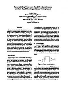
1.1.1. Picture It!: A Distributed Scenario Microsoft Picture It! [79] typifies a class of compelling applications needing distribution. Picture It! is a photo editing program similar to Adobe’s Photoshop [2]. Taking input from high-resolution, color-rich sources such as scanners and digital cameras, Picture It! produces output including greeting cards, collages, or publications. Picture It! provides tools for selecting a subset of an image, applying a set of transforms to the subset, and inserting the transformed subset into another image. Composed of several dozen COM component classes, the commercial version of Picture It! is a non-distributed application; it was designed to run on a single computer.
Image Merge Edge Sharpen Resolution Reduction
User’s Workstation Transformations
Photo Clearinghouse Figure 1.1. A Distributed Picture It! Scenario. Input files are loaded from a remote image clearinghouse, modified with transformations, and displayed on the user’s workstation. In a typical scenario, Picture It! might be used to produce the cover for an online automotive magazine. For this month’s cover on favorite import roadsters, the cover designer downloads images of a Ferrari, a Lamborghini, and a Fiat from a photo clearinghouse. The photo clearinghouse maintains an extensive database of high-resolution images. The designer applies transforms to rotate each car’s
5
photo, reduce its resolution for 72 DPI on-line display, and place it on the cover. For added emphasis, the designer applies an edge sharpening transform to the photo of the Fiat. The creation of the magazine cover is a distributed computation. As can be seen in Figure 1.1, the original photos are located remotely at the photo clearinghouse. Final output is displayed on the designer’s workstation and saved at a different remote server. Between the remote input and local output, a number of computationally intensive transformations must be applied. Picture It! has no explicit distribution code. In the described scenario, Picture It! could retrieve images from the photo clearinghouse using a file transfer protocol such as NFS [67], SMB/CIFS [60], or FTP [96]. The input images might be extremely large: on the order of tens to hundreds of megabytes. To avoid loading the input images across the network, the designer could run Picture It! remotely on the clearinghouse’s computer using a remote windowing system such as the X Window System [104] or the Window-based Terminal Server [81]. Unfortunately, a remote windowing protocol might also transfer large amounts of data due to the interactive nature of the Picture It! application. Both file transfer and remote windowing transfer large amounts of data because they are unable to distribute portions of the application. A programmer explicitly distributing the Picture It! application would notice that many transforms, such as resolution reductions or color reductions output fewer bytes than they input. The programmer would probably decide to run some of the transforms at the photo clearinghouse with the rest of the application running on the designer’s workstation.
By
explicitly distributing the application between transforms, the programmer makes application-specific distribution choices that significantly improve performance of the distributed application. Such a static choice of distribution won’t necessarily meet the needs of a different user.
1.1.2. Distributed Partitioning Choosing an appropriate distribution is critical to the performance of the distributed application. An ill-partitioned application can suffer serious performance penalties due to excessive network communication. Optimally partitioning a distributed application to reduce network communication costs is difficult due to the large space of potential choices. A distributed application with c components running on n machines has O(nc) possible distributions. Not only is the space of potential solutions large, but the shape of the solution space is extremely complex. It is difficult to predict the exact effect of moving any single unit of data or code from one machine to another. An efficient distributed partitioning decision should take into consideration the following factors:
6
• Relative and absolute machine resources. In general, machine resources include memory and processor cycles. Absolute resource values include the total memory on the machine available to the application and the speed of the machine’s CPU. The total memory on the machine becomes very important to application throughput if, for example, memory is over-committed, causing the virtual memory system to page to disk excessively.
Relative resources are
important in balancing load between machines. • Per-connection machine-to-machine latency. Latency determines how long it takes to get a message from one machine to another.
Calculating a value on an extremely fast remote
machine is futile if the time to invoke the calculation dwarfs the time to calculate it locally. • Per-connection machine-to-machine bandwidth. Bandwidth determines how much data can be sent to another machine during a certain period. An application sending large quantities of data across a low bandwidth connection will suffer serious performance degradation. • Network topology. The topology determines which machines may communicate directly and how messages bound for distinct machines might interact. For instance, on a broadcast medium such as Ethernet, messages between disjoint machines compete for the shared network. Alternatively, in point-to-point networks, aggregate bandwidth is the sum of all link bandwidths. Complicating the choice of an application distribution are evolutionary factors. For instance, advances in technology have significantly increased machine-to-machine bandwidths, while relative latencies have not seen comparable improvements. As another example, an application might improve its performance by using broadcast on a shared medium such as Ethernet. Future changes in machine resources, network characteristics, or even incremental application changes can all change the tradeoffs in a distributed application. Even within an organization, different users may have access to different networking or distributed resources depending on their geographic location or organizational status. A sound distribution coded into the application today might become a serious weakness in the future. Table 1.1 lists basic network parameters and roundtrip communication costs for RPC messages. Numbers were measured with a symmetric pair of 233MHz Pentium PCs. Not only does the available bandwidth change from one network to another, but also the cost ratio of sending a small message versus a large message. The change in the large-to-small ratio is due to the relative independence of network bandwidth and network latency. Any change in bandwidth, latency, or both has the potential to change the communication costs between components. A typical distributed application today might be deployed initially on a 10BaseT Intranet. In the future, the company’s internal network may be upgraded to 100BaseT or ATM. Users at remote
7
offices might need to access the application over an asymmetric digital subscriber line (ADSL) connection with 1.54Mbps downstream and 64Kbps upstream bandwidth. Each of these networks has a drastically different latency cost and available bandwidth.
Network
Raw Bandwidth
Available Bandwidth
Null RPC Round Trip
32KB RPC Round Trip
Ratio, 32KB to 0KB RPC
ATM
155 Mbps
71.5 Mbps
519 µs
3.62 ms
7:1
100BaseT
100 Mbps
44.1 Mbps
383 µs
5.67 ms
15 : 1
10BaseT
10 Mbps
7.8 Mbps
636 µs
32.0 ms
50 : 1
ADSL Central
1.384 Mbps
1.1 Mbps
28.2 ms
220 ms
8:1
ADSL Remote
64 Kbps
54.8 Kbps
31.7 ms
4.56 s
144 : 1
ISDN (1 Chan.)
64 Kbps
53.5 Kbps
59.4 ms
4.67 s
79 : 1
Table 1.1. Basic Network Information. RPC times for a round-trip message. The specified message size is number of bytes sent from client to server. The return message contains only a result code. We claim that the appropriate distribution strategy is to partition an application into as many logical components as possible and leave component placement to system software. Experimental evidence in this dissertation will demonstrate the feasibility and efficiency of automatic distributed partitioning. It will show that automatically distributed programs can readily be adapted to new networking environments and user usage patterns without modification of source code. Rather than modify application sources, we can automatically modify distributed partitioning information embedded in the application binary, based on run-time statistics, to take into account changes in network topology and configuration.
1.2. Solution Domain: COM Microsoft Corporation’s Component Object Model (COM) sets a standard for dynamically connecting units of software called components through connections called interfaces. A COM component is a reusable piece of software in binary form. One or more components can be grouped together to form an application. COM was originally developed as part of the second generation of Microsoft’s Object Linking and Embedding (OLE), a document-centric computing architecture. OLE programs, as exemplified by the applications in Microsoft Office, can share functionality within a single document. For example, a
8
Microsoft Excel spreadsheet can be embedded within a Microsoft Word document, which can then be embedded in a Microsoft PowerPoint presentation. For the user, OLE makes multiple applications function as one. Synthesizing a single user-experience from multiple applications required a great deal of inter-process communication. The original version of OLE used an IPC mechanism called Dynamic Data Exchange (DDE).
DDE passed data asynchronously through window event queues.
It was cumbersome,
difficult to program, and very error prone. To overcome limitations in DDE, OLE’s principal architects, Tony Williams and Bob Atkinson, conceived of the technology now known as COM. The central feature of COM is the interface, a communication connection between two components. Interfaces are strongly typed and polymorphic. More than just a communication channel, an interface represents a dynamic contract between two components regarding the semantics of their communication.
Any client can connect to any
component as long as the two support a common interface. From the perspective of this thesis, an interface’s most important feature is support for transparent invocation.
Implementations of both the client and component remain unchanged regardless of
whether they share an address space, are located in separate address spaces on the same machine, or are located on completely separate machines. True location transparency places some restrictions on component design. Specifically, COM defines rules for memory allocation when passing pointer-rich data structures between components. Within an address space, components share such data structures. When execution transfers between address spaces, data is copied from the source to the target using deep-copy semantics. The interface definition language (IDL) used by COM supports roughly a dozen annotations for optimizing data copy operations between machines. COM has proven itself an excellent environment for building component-based desktop applications. Binary reusability was instrumental in creating a $410M/year market for COM components in 1997 (up 71% from the year before) [38]. The publication of the Distributed COM (DCOM) wire protocol as an IETF working draft [15] and its availability on a wide range of platforms has made COM a viable mechanism for creating distributed applications.
1.3. Thesis Statement It is both possible and beneficial to automatically partition and distribution applications without source code provided the applications are built from distributable binary components. The Coign ADPS proves both of these claims. Coign has successfully partitioned three real COM applications, including
9
Microsoft Picture It!. These applications were partitioned without programmer intervention or access to source code. While not comprehensive, these applications represent different COM programming styles and are—to the best of our knowledge—some of the most complex COM applications currently in existence. It is reasonable to assume that they represent a large class of COM applications. Quantitatively the benefit of automatic distributed partitioning is determined by the performance of the chosen distribution.
Using techniques described in this dissertation, it is possible to choose a
distribution for a given COM application that minimizes communication costs.
Ultimately, the
performance of a selected application distribution is a function of the granularity and quality of the application’s components and the appropriateness of the profiling scenarios used to measure internal application communication. While Coign cannot improve an application’s design, it can achieve the best possible distribution of that design subject to the profiling scenarios.
As a corollary, this
dissertation suggests a number of guidelines to aid the creation of components and applications amenable to automatic distributed partitioning. Automatic distributed partitioning frees the programmer from “hard-coding” a particular application distribution. In non-automated environments, the programmer typically chooses a specific distribution based on past experience, intuition, or data gathered from a prototype application. The application’s design is then tailored to the chosen distribution. At best, the programmer has chosen a good presentday distribution that might be rendered obsolete by changes in network topology.
At worst,
assumptions used in choosing the distribution are later proven incorrect resulting in an application poorly matched to its intended environment. Automatic distributed partitioning reduces the programmer’s burden. Rather than code for a specific distribution, the programmer is encouraged to create easily distributed components. Emphasis is placed on code reusability, component autonomy, and choice of appropriate algorithm and data abstractions—all elements of good software engineering. In essence, automatic distributed partitioning makes the most of good software engineering by raising the level of abstraction for the distributed programmer. In contrast, manual distributed partitioning forces the programmer to be keenly aware of how an application will be distributed.
1.4. Issues for Automatic Distributed Partitioning Automatic distributed partitioning of applications is an ambitious endeavor balancing logical ideals and logistical details. To describe it, we introduce the notion of an automatic distributed partitioning system (ADPS). The ADPS takes as its input a program designed to run on a single computer. The
10
ADPS modifies the program to produce a distributed version that minimizes network communication costs. At a high level the problem of automatic distributed partitioning can be divided into three subproblems: • Discovery: Discovering how the application can be partitioned.
To solve the discovery
problem, individual pieces of the application must be identified, and communication and creation relationships between the pieces must be identified and quantified. • Decision: Deciding how the application should be distributed. While an application can be partitioned in many ways, not all of them will yield equivalent performance. Application distributions that reduce the number and size of distributed messages are most likely to exhibit good performance. • Distribution: Achieving a chosen distribution. The program’s execution must be modified to produce the selected distribution chosen as a solution to the decision problem.
1.4.1. Discovery: Understanding Application Behavior Distributed partitioning is complicated by interactions between code modules, between data structures, and between both code and data. For instance, one data structure may contain a pointer to another data structure. If either data structure is naively relocated to another machine without modification, an attempt to de-reference the pointer will fail, most likely producing a virtual memory fault. Automatic distributed partitioning requires that either the programmer or the computer system explicitly manage code and data interactions crossing machine boundaries. A major difficulty in automatic distributed partitioning is qualifying, quantifying, and managing the interactions between distribution units. An ADPS requires detailed knowledge of the structure and behavior of the target application. Data must be gathered on how the application can be divided into distributable pieces and how those pieces interact. ADPS functionality and effectiveness is limited by the granularity of distribution units, availability of structural metadata, choice of application analysis technique, representation of communication information, and mechanisms for determining location constraints on application pieces.
Distribution Granularity The granularity at which an application is divisible severely impacts the potential for improving performance of its distribution.
Distribution granularity dictates the smallest independently
11
distributable unit of the application. The number of potential distributions is inversely related to the distribution granularity. performance.
If the number of distributions is insufficient, none may offer good
However, if the granularity is too small, the tasks of choosing and realizing a
distribution may become prohibitively expensive. Perhaps even more importantly, the choice of partitioning unit shapes the relationships between partitioned granules. For instance, many DSM systems partition programs into VM pages. A single VM page often contains objects whose only commonality is their locality in creation time. The relationship between adjacent VM pages may be even more tenuous. Ideally, data within a distribution granule will exhibit good temporal and contextual locality. The ADPS cannot choose granularity directly. The choice of distribution granularity is determined by the choice of operating environment. For instance, the distribution granularity in Coign is a direct result of implementing the system on COM.
An ideal environment for automatic distributed
partitioning should provide a granularity of distribution with sufficient options to make automated partitioning worthwhile. The ideal granularity should match available metadata and provide a good “fit” to the application’s structure.
Structural Metadata Distributed partitioning divides an application into distributable pieces. Division requires access to appropriate metadata describing program structure. Program metadata can be gathered from any of several sources including a compiler intermediate representation (IR), application debugging information, an interface definition language (IDL), and memory access data from the virtual memory (VM) system. The structural metadata must provide the ADPS with sufficient information to separate application pieces and to manage code and data interactions among remote pieces of the application.
Application Analysis The choice of application analysis technique determines the type of application behavior visible to the ADPS. A fully functional ADPS requires whole program analysis with complete information about the application’s components, their dynamic instantiation relationships, and their communication patterns. Static analysis of whole applications is extremely complex and virtually impossible on commercial binaries without source code. Static analysis also deteriorates when application execution is data or input driven.
12
Dynamic analysis, on the other hand, provides insight into an application’s run-time behavior. Major drawbacks of dynamic analysis are the difficulty of instrumenting an existing application and the potential perturbation of application execution by the instrumentation. Techniques such as sampling or profiling reduce the cost of instrumentation. However, the former is only statistically accurate whereas the latter requires that profile scenarios accurately represent the day-to-day usage of the application.
Communication Representation Precise distributed partitioning analysis requires an accurate picture of the cost to distribute each piece of an application. Communication costs can be represented through several abstractions. For instance, communication costs can be represented as the time to transmit data from one machine to another or the amount of data transmitted. The former is network-dependent and will change with network interconnection. The latter fails to consider the realities of network latencies and bandwidths. An appropriate cost abstraction should be network independent, but allow realistic analysis of distribution tradeoffs. The abstraction used in Coign summarizes number and size of network packets independent of physical network. Immediately prior to distribution, the summary is combined with basic statistics about a physical network to calculate network-dependent communication costs.
Determining Location Constraints While ideally any piece of an application can be relocated, the physical location of resources places constraints on distributed partitioning. The most common form of distribution constraint is application communication through second-class communication mechanisms. A typical example of a secondclass communication mechanism is a Unix file descriptor.
The file descriptor represents a
communication channel between the operating system and application. The file descriptor is a secondclass mechanism because it cannot be directly distributed with first-class mechanisms, such as shared memory in a DSM system or interfaces in COM. The file descriptor implicitly constrains program location. An ADPS must recognize and respect existing location constraints.
1.4.2. Decision: Choosing a Distribution Given an application, the ADPS must decide where to distribute its pieces. Creating an efficient distribution requires judicious management of communication costs.
Because distributed
communication is much more expensive than local communication, a distribution should minimize the amount of inter-machine communication. In addition to communication overhead, the ADPS should take into consideration relative computation costs and resource availability.
Abstractly, the
13
distribution decision consists of a distribution model and cost metric that encode the decision problem for a particular application and an algorithm for optimizing the model.
A
A
B
C
B
C
D
E
D
E
F
F
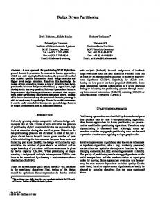
Figure 1.2 The Decision Problem. Given a graph of components and their connections, the ADPS must choose a component distribution to partition the graph between networked machines.
Distribution Model The ADPS must model the tradeoffs between candidate distributions.
Distribution costs can be
considered either directly or indirectly. Direct models specifically include communications costs and resource availability. Indirect models consider contributing factors such as data or temporal locality. The choice of model determines which kinds of input data are required and which factors the optimizing algorithm maximizes. One very useful model of the distribution problem represents the application as a connected graph. Nodes represent distributable pieces of the application and edges represent interactions between pieces. Edges are weighted with the relative cost of the interaction if remote.
Distribution Optimization Algorithms The distribution optimization algorithm accepts a model of the decision problem and maps it onto a computer network. In the case of a simple client-server network, the optimization algorithm most easily applied is a MIN-CUT MAX-FLOW algorithm [40]. For networks of three or more machines, the problem is provably NP-hard and approximation techniques must be used to partition the application across the network [24].
14
Choosing a Distribution Online If all distributed partitioning decisions are made offline, data for a particular network can be gathered from a large number of samples. In a dynamic environment where bandwidth and network availability may change from one execution to another, it is desirable to make distributed partitioning decisions online at application startup. Data for online decision-making must be gathered while the user waits. This creates a serious constraint on the number of samples used to determine available latency and bandwidth and model of network communication costs.
1.4.3. Distribution: Creating the Distributed Application Ultimately, the ADPS must modify the application to achieve the desired distribution. Achieving a distribution consists of two important steps: identifying application components and distributing them to the correct machine.
Component Classification One of the most difficult problems in automatic distributed partitioning is correlating data gathered from scenario-based profiling with later application executions. Through scenario-based profiling, the ADPS creates a profile of each component in an application.
The profile characterizes the
communication of the component with other components in the application and any relevant location constraints. The ADPS solves the distributed-partitioning decision problem by deciding where to distribute components created in profiling scenarios. Unfortunately, the profiling scenarios may never run again. The application may never use the exact same components again. Instead, the application will run on new input and will instantiate new components. To efficiently distribute the application in subsequent executions, the ADPS must be able to predict future application behavior based on information from the profiling scenarios. The output of scenario-based profiling and the distribution decision is a mapping of profiled components to networked computers. To partition the application during later executions, the ADPS matches each new component with the most similar profiled component. The problem of component classification is relevant within a single execution and across multiple executions.
The ADPS
classifies groups of similar components from multiple profiling scenarios. Difficulties in component classification arise because components are dynamic objects. Components may be instantiated at any point in the execution of a program. Multiple instances of the same type of
15
component may exist simultaneously. To produce a chosen distribution, the ADPS must be able to accurately classify all application components.
A
A
B C
B
C
D
E
Time
CoCreateInstance(Class1) { CoCreateInstance(Class2) { CoCreateInstance(Class3) } CoCreateInstance(Class3) }
D
…
F
Figure 1.3. The Component Classification Problem. Given a request to instantiate a new component during program execution (on the left), the ADPS must find the most similar profiled component (on the right). Figure 1.3 presents the component classification problem in context. During execution, an application dynamically instantiates a number of components. The ADPS must match each new component with a profiled component used in the decision problem. The ADPS classifies components according to their expected communication behavior. Given a matching communication profile, the ADPS directs the placement of the new component to achieve an optimal application distribution.
Distributing Components Creating a distribution is achieved by manipulating an application’s execution. There are three classes of solutions to accomplish this task: modify the application’s source code, modify the application’s binaries prior to execution, or manipulate the application’s execution through run-time intervention. Static modification of application source code or binaries is extremely difficult because it requires problematic whole-program static analysis. Manipulating the application’s execution through run-time intervention is relatively straightforward but has some limitations.
In general, an application’s
execution can be manipulated to produce a chosen distribution efficiently by intercepting component instantiation calls and executing them on the appropriate remote host.
1.5. Dissertation Organization The remainder of the dissertation is organized as follows. Chapter 2 presents background information about distributed systems and component systems. It contains a survey of related work in the field of
16
distributed application partitioning, and compares and contrasts this dissertation with prior work. Chapter 3 describes in detail general problems and issues related to automatic distributed partitioning. Among other things, it discusses the problem of component classification. The solutions in Chapter 3 are applicable to any ADPS. Chapter 4 gives a high-level overview of Coign, an experimental ADPS system implemented on COM on the Windows NT platform. It presents experimental evidence demonstrating the feasibility of automatic distributed partitioning and describes the performance of the automatically distributed applications. Chapter 5 details the implementation of Coign. The discussion places particular emphasis on the instrumentation to quantify program behavior as it relates to automatic distributed partitioning. Many of the instrumentation techniques in Chapter 5 are applicable to any instrumentation system for COM components and applications. Finally, Chapter 6 summarizes the findings of this dissertation, provides a few guidelines for developers of component-based applications, and suggests promising directions for future research in automatic distributed partitioning and in the high-level analysis of applications using run-time instrumentation.
17
2. Background and Related Work
Distributed systems have been a fertile field of research for several decades. If anything, interest in the area has increased in the last few years. The increase is fueled by the growing importance of the global Internet. Research in distributed systems is both abundant and diverse. Automatic distributed partitioning represents only a fraction of the open research in distributed systems. This dissertation is not so ambitious as to attempt to describe the entire field. The discussion in this chapter is limited to those areas of research most directly related to automatic distributed partitioning. The first section introduces prior research in automatic distributed partitioning. The next section provides an overview of Microsoft’s Component Object Model (COM) and compares COM to the Object Management Group’s Common Object Request Broker Architecture (OMG CORBA). Subsequent sections describe related work in object-oriented distributed systems, parallel task partitioning and scheduling, and structural application analysis.
2.1. Automatic Distributed Partitioning Internal and External Distribution Mechanisms For the purposes of this dissertation, distribution mechanisms can be divided into two categories: internal distribution mechanisms and external distribution mechanisms.
We define internal
distribution mechanisms as those that allow distribution through internal modification of an application. Internal distribution mechanisms include remote procedure call (RPC), distributed shared memory (DSM), and network sockets. We define external distribution mechanisms as those that allow distribution without any modification of an application. External distribution mechanisms include network file systems and remote windowing systems.
18
External distribution mechanisms are easy to use and very flexible. In the scenario in Chapter 1, the Picture It! application could retrieve images from the photo clearinghouse using an external distribution mechanism such as NFS. Alternatively, to avoid loading images as large as hundreds of megabytes across the network, the designer could run Picture It! remotely on the clearinghouse’s computer using a remote windowing system. However, the windowing system might transfer large amounts of data due to the interactive nature of the Picture It! application. Although they require extra programmer effort, internal distribution mechanisms are widely used because they allow application-specific distribution optimizations.
A programmer explicitly
distributing the Picture It! application might notice that some transforms, such as resolution reduction or color reduction, produce much smaller data sets than they consume. The programmer would probably decide to run the data reduction transforms at the photo clearinghouse with the rest of the application running on the designer’s workstation. By splitting the application between transforms with internal distribution mechanisms, the programmer has applied application-specific optimizations that significantly improve performance of the distributed application. The primary disadvantage of internal distribution mechanisms is that they often lead to ad hoc, onetime solutions with implicit assumptions about distribution costs. A distribution that works well on a local area network probably won’t work as well for remote users telecommuting over ISDN. Both external and internal distribution mechanisms have drawbacks. External distribution mechanisms don’t take advantage of application-specific distribution optimizations.
Internal distribution
mechanisms require extra programmer effort and suffer performance loss when the assumptions underlying the chosen distribution change.
The goal of an ADPS is to maximize distributed
performance by minimizing communication costs through optimizations available only to internal distribution mechanisms while providing ease-of-use similar to that of external distribution mechanisms
Properties Necessary for an ADPS In Chapter 1, we introduced the notion of an ADPS. We refine this notion here. The implementation of an ADPS requires five key properties of the underlying system: structurally identifiable and isolatable application pieces, location-transparent invocation, descriptive inter-piece metadata, a distribution optimization algorithm, and an application manipulation mechanism. Without any of these five properties, an application cannot be automatically distributed. These properties must exist in the underlying system or be added by the ADPS.
A sixth property, usable distribution granularity,
19
determines how effective the application partitioning system will be in optimizing distributed application performance. In more detail: • Structurally identifiable and isolatable application pieces. The ADPS must be able to identify the pieces of an application that might be distributed. The ADPS must also be able to distribute these pieces independent of the rest of the application. • Location-transparent invocation.
The ADPS must be able to distribute a piece of the
application without modifying any part of the application’s behavior other than its performance. • Descriptive inter-piece metadata.
The ADPS must be able to identify and quantify
communication and execution flow between application pieces. Inter-piece metadata describe the data communicated between application pieces. • Distribution optimization algorithm. The ADPS must be able to reason about possible distributions and select an optimal distribution of the application to minimize communication. • Application manipulation mechanism.
The ADPS must be able to manipulate the
application’s execution to produce a chosen distribution. • Usable distribution granularity.
The granularity of the application’s pieces (or, more
precisely, the granularity with which application pieces can be distributed) ultimately limits the choices available to the ADPS and therefore the effectiveness of any application distribution. In the case of Coign, the underlying COM system provides structurally isolatable application pieces, location transparency, and descriptive inter-piece metadata. To these properties, Coign adds a runtime system and tools for choosing a distribution and modifying the application. Experimental data in Chapter 4 verifies the appropriate granularity of COM components.
2.1.1. ICOPS The Interconnected Processor System (ICOPS) [72, 109, 117] was the first ADPS. Developed at Brown University in the 1970’s under the leadership of Andries van Dam, ICOPS pioneered the use of compiler-generated stubs for inter-process communication.
ICOPS was the first system to use
scenario-based profiling to gather statistics for distributed partitioning; the first system to support multiple distributions per application based on host-processor load; and the first system to use a minimum-cut, maximum-flow (MIN-CUT MAX-FLOW) algorithm to choose distributions. ICOPS was implemented on a host/satellite system consisting of an IBM S/360-67 timesharing system and two Digital Scientific Meta-4 minicomputers. One of the Meta-4 machines was dedicated to
20
driving a vector display. The second Meta-4 ran application code. The host and satellite were connected through a high-speed interface. ICOPS provided a virtual uniprocessor environment by moving execution and data seamlessly between the S/360 and the Meta-4. Applications for the ICOPS system were developed with a customized ALGOL-W compiler. The compiler emitted code for both the S/360 and the Meta-4. The link-edit preprocessor (LEPRE) merged object modules created by the compiler to create the final application.
Through a script, the
programmer notified LEPRE of the possible location (on the satellite, the host, or both) of each procedure. Using data in the symbol table emitted by the ALGOL-W compiler, LEPRE created stubs for remote procedure invocation and metadata for communication measurement in the ICOPS runtime. The ICOPS system evaluated distributions through scenario-based profiling. During profiling, an application was run through a number of scenarios. The ICOPS runtime trapped every procedure call and return to record in a trace file the number and size of parameters. The ICOPS runtime also recorded procedure execution time and time spent waiting for the user. ICOPS analyzed dynamic data from the runtime and static data from the compiler to choose a distribution. ICOPS supported distribution on a per-procedure basis. The partitioning decision itself was made by applying a MIN-CUT MAX-FLOW algorithm [35]. The output of the decision process was a library of distributions—each optimized to increase application response time by minimizing communication cost for a specific range of host processor loads. During application execution, the user could interrupt the program and redistribute it according to one of the pre-computed distributions. The ICOPS runtime provided the user with information about the host-processor load to aid in the selection of a distribution. ICOPS was used to automatically distribute HUGS, a two dimensional drafting program developed at Brown. HUGS consisted of seven modules. Of the seven modules, three modules—consisting of 20 procedures in all—could be located on either the satellite or the host. In addition to the ICOPS system, the Brown group identified three important properties of any target language for an ADPS (in their terminology, an Interconnected Processing (ICP) system [117]): • Machine Transportability. Due to the inherently heterogeneous nature of their development environment, they recognized the importance of having a single language that could be compiled to two target machines from common source code.
They achieved machine
transportability by customizing the ALGOL-W compiler and rewriting the microcode on the Meta-4.
21
• Procedure Oriented. ICOPS distributed applications at the granularity of the procedure. Consequently the Brown group identified procedure orientation as a necessary attribute of languages used in ICP systems. • Symbol Table Output. The Brown group stated that in order to move execution between two machines, “it is absolutely necessary that the compiler for the language retain complete information about all symbols (and parameters) defined by the programmer.” The important properties identified by the Brown group demonstrate an early view of the notion of an ADPS. Machine transportability is a very important property for creating distributable applications on networks of heterogeneous machines. In the context of the ICOPS system, machine transportability meant that the system provided a cross compiler capable of generating code for either the host or the satellite. In the last two decades, machine transportability, as emphasized in ICOPS, has been largely addressed by language standards, such as the ANSI C standard [105]. Procedure orientation is subsumed by object orientation in systems such as COM. However, fully distributable COM components can be created in relatively non-procedural languages such as scripting languages. It appears that the properties the Brown authors were trying to identify in citing procedure orientation were usable distribution granularity and, more importantly, structurally identifiable and isolatable application pieces. The need for symbol table output can be attributable to two ADPS properties: dynamic metadata for measuring communication and static metadata for separating distributable pieces of the application. Aside from separating distributable application pieces, the need for symbol table output has been removed in modern systems by the separation of the RPC [88, 123] abstraction which gathers symbolic information for distributed procedures from an interface definition language (IDL).
2.1.2. CAGES The Configurable Applications for Graphics Employing Satellites (CAGES) [46, 47] system shared similar goals with ICOPS. CAGES attempted to provide an environment in which the programmer could develop an application for a single computer and later distribute the application across a hostsatellite system. Unlike ICOPS, CAGES did not support automatic distributed partitioning. Instead, the programmer provided a pre-processor with directions about where to place each program module. The programmer could change a distribution only after recompiling the application with a new placement description file.
Like ICOPS, CAGES was procedure-oriented; programs could be
distributed at the granularity of procedural modules in the PL/I language. To aid the programmer in choosing a distribution, CAGES produced a “nearness” matrix through static analysis. The “nearness”
22
matrix quantified the communication between modules, thus describing how “near” the modules should be placed to each other. One important advantage of CAGES over ICOPS was its support for simultaneous computation on both the satellite and the host computers. CAGES provided the programmer with the abstraction of one dual-processor computer on top of two physically disjoint single-processor computers.
The
CAGES runtime provided support for RPC and asynchronous signals. CAGES gave the programmer a more robust development environment to compensate for the lack of automatic distributed partitioning. CAGES was used to create distributed versions of two applications [46].
The first application,
MEDICS, was an interactive application designed to fit a curve to set of data points. The original MEDICS program consisted of 14 modules. After initial analysis, graphics code in each of the modules was separated from computation to create 14 new modules. Of these modules, five were placed on the satellite producing a two-fold improvement in application execution time. The second application distributed with CAGES was BLOCKS, a program for creating and manipulating block diagrams such as electronic schematics. The original BLOCKS program consisted of 17 modules. Using CAGES, the authors compiled BLOCKS for four separate distributions. Over successive distributions, the authors were able to improve execution time by 30% through changes isolated to the placement description file. Both ICOPS and CAGES were severely constrained by their granularity of distribution: the ALGOLW or PL/I procedural module. Neither system ever distributed an application with more than a few dozen modules. However, despite their weaknesses, both systems provided a level of support for automatic or semi-automatic distributed application partitioning.
2.1.3. VisualAge Intelligent Dynamic Application Partitioning Kimelman et al. [58] describe the Intelligent Dynamic Application Partitioning (IDAP) system, an ADPS for Smalltalk applications.
IDAP is an add-on to IBM’s VisualAge Generator.
Using
VisualAge Generator’s visual builder, a programmer creates an application by instantiating and connecting components in a graphical environment. The builder emits code to create the application. VisualAge Generator includes the Interactive Test Facility for running the generated application through test scenarios. IDAP exploits the Interactive Test Facility to gather scenario-based profiling information about the application. After generating a version of the application with an instrumented message-passing mechanism, IDAP runs the instrumented application under control of the test facility.
23
The word dynamic in the IDAP name refers to this use of scenario-based profiling as opposed to static analysis to gather data about the application. The instrumented program displays a graphical window showing icons for each application component and links—drawn as springs—between connected components.
Every time a message is passed
between two components, the tension on the spring between the components increases. Over time, components move to reduce the tension on connecting springs.
This movement provides the
programmer with visual feedback about which components communicate frequently and should probably be placed together. After the application has executed, the programmer either manually partitions the components or invokes an automatic graph-partitioning algorithm. The algorithm used is an approximation algorithm capable of multi-way cuts for two or more hosts [24]. After choosing a distribution, VisualAge generates a new version of the application. IDAP supports distributed partitioning only for statically allocated components. Although initially based on Smalltalk, the distributable components are large-grain components, not the fine-grained objects native to Smalltalk. Kimelman’s team has tested their system on a number of real Smalltalk applications, but in each case, the application had “far fewer than 100” components [58]. The latest version of IDAP generates C++ code for connecting CORBA components, but still does not support dynamic component instantiation [53]. Moreover, the use of CORBA restricts IDAP to a distribution granularity of operating-system processes because CORBA does not support loading client and component code into the same address space. The IDAP programmer must be vary aware of distribution choices. IDAP helps the user to optimize the distribution, but does not raise the level of abstraction above the distribution mechanisms.
With a full-featured ADPS, such as Coign, the
programmer can focus on component development and leave distribution to the system.
2.1.4. Summary The automatic distributed partitioning systems of the 1970’s were inadequate for commercial applications distributed in binary form. The systems developed by van Dam and Foley were tied to a single language and compiler. Each system relied on metadata generated by the compiler to facilitate transfer of data and control between computers. Modules compiled in another language or by another compiler could not be distributed because they did not contain appropriate metadata. These systems gave the application the luxury of location transparency, but still required the programmer or user to explicitly manage distribution at run time. A major focus of both the ICOPS system and the CAGES system was support for networks of heterogeneous systems.
24
The VisualAge IDAP contains a number of improvements over the ICOPS system. The most notable improvements are support for multiple languages and the use of a multi-way graph-partitioning algorithm.
Although it supports multiple languages, IDAP still requires that applications be
constructed with a single application-development toolkit, the VisualAge Generator. Like ICOPS and CAGES, IDAP supports automatic distributed partitioning of static application pieces only. In the case of ICOPS and CAGES, the application pieces are procedures. In the case of IDAP, the pieces are CORBA components or Smalltalk components.
None of these systems allows
distributed partitioning of components dynamically instantiated during the execution of the application. Dynamic component instantiation is an integral feature of modern desktop applications. Automatic distributed partitioning of dynamic components requires an acceptable solution to the problem of component classification to be described in Section 3.1. Our research differs in scope from prior work because we attempt to automatically distribute an existing class of commercial applications. All of the applications in our test suite were developed by third parties prior to the design of Coign.
2.2. Component Systems Perhaps the most important advance in software engineering in the last decade has been the advent of commercial component systems. Component systems allow the assembly of applications from readymade components. At least one commercial component system, Microsoft’s Component Object Model (COM) provides sufficient metadata and appropriate granularity for automatic distributed partitioning of applications built from commercial, binary components.
2.2.1. COM As introduced in Chapter 1, COM is a standard for creating components—reusable pieces of software in binary form. Programmers can easily build applications from components, even components for which they have no source code. COM’s major features include multiple polymorphic interfaces per component, standard-mandated binary compatibility, and location-transparent invocation.
2.2.1.1. Interfaces All first-class communication in COM takes place through interfaces. An interface is a strongly typed reference to a collection of semantically related functions.
25
[uuid(00000000-0000-0000-C000-000000000046)] interface IUnknown { HRESULT QueryInterface([in] REFIID riid, [out, iid_is(riid)] IUnknown **ppObj); ULONG AddRef(); ULONG Release(); }; [uuid(b3c11b80-9e7e-11d1-b6a5-006097b010e3)] interface IStream : IUnknown { HRESULT Seek([in] LONG nPos); HRESULT Read([out, size_is(cb)] BYTE *pb, [in] LONG cb); HRESULT Write([in, size_is(cb)] BYTE *pb, [in] LONG cb); }; Figure 2.1. IDL for Two Interfaces. The IDL definition of an interface describes its member functions and their parameters in sufficient detail to support location-transparent invocation.
Interface Definition Language (IDL) Figure 2.1 contains the definitions of two interfaces: IUnknown and IStream. Interfaces are defined using a special language, the Interface Definition Language (IDL). An IDL compiler maps the interface definitions into a standard format for languages such as C++, Java, or Visual Basic. The IDL-generated interface prototypes facilitate usage of components in a language-neutral manner. Each interface declares a set of functions. IDL does not provide an implementation for an interface; it merely defines the format of the interface.
Each interface function can have any number of
parameters. To clarify semantic features of the interface, IDL attributes can be attached to each interface, member function, or parameter. For example, the size_is(cb) attribute on the pb argument of the Write function in Figure 2.1 declares that pb is an array with cb elements. In IDL syntax, attributes are enclosed in square brackets ([]). Attributes specify features such as the data-flow direction of function arguments, the size of dynamic arrays, and the scope of pointers. Syntactically, IDL is very similar to C++.
IUnknown The IUnknown interface, listed in Figure 2.1, is special.
All COM components must support
IUnknown. Each COM interface must include the three member functions from IUnknown, namely: QueryInterface, AddRef, and Release.
AddRef and Release are reference-counting
26
functions for lifetime management. Whenever a client of a component creates a new reference to the component, it calls AddRef. When it is finished using the reference, it calls Release. Through the AddRef and Release functions, a component knows exactly how many clients have references to it. When its reference count goes to zero, the component is responsible for freeing itself from memory. Components can support multiple interfaces. Clients dynamically bind to a new interface by calling QueryInterface. QueryInterface takes as input a globally unique identifier for the interface to which the client would like to bind and returns a pointer to the new interface. Through run-time invocation of QueryInterface, clients can determine the exact functionality supported by any component. class IUnknown { public: virtual HRESULT QueryInterface(REFIID riid, IUnknown **ppObj) = 0; virtual ULONG AddRef() = 0; virtual ULONG Release() = 0; }; class IStream : IUnknown { public: virtual HRESULT Seek(LONG nPos) = 0; virtual HRESULT Read(BYTE *pb, LONG cb) = 0; virtual HRESULT Write(BYTE *pb, LONG cb) = 0; }; Figure 2.2. C++ Language Mapping. The midl compiler maps the IDL description of an interface into a C++ definition. As per COM and C++ conventions, each member function has an implicit “this” parameter.
Globally Unique Identifiers All COM interfaces are named by a globally unique identifier (GUID). GUIDs are 128-bit values that with very high probability are truly unique. The algorithm for allocating GUIDs factors in quantities including the identity of the allocating machine’s network adapter and the current date and time to insure that each new GUID is unique in the world across both space and time. Each COM interface has a specific GUID. The [interface, GUID] pair is immutable. If the interface is modified, such as by adding or removing a member function or by changing the interface’s semantics,
27
a new GUID is generated to describe the new interface. An interface’s GUID represents an immutable contract covering both function signatures and semantics between client and component.
Language Mapping Figure 2.2 contains the C++ definitions generated by Microsoft’s IDL compiler, midl, for the IDL interfaces in Figure 2.1. An IDL interface maps into a C++ abstract class. Components support interfaces by multiply inheriting the desired interfaces and implementing their member functions. IDL has straightforward mappings into other compiled languages such as C and Java. In addition, midl can export compiled metadata to a specially formatted file called a type library. Type libraries can be imported by many development tools. Type libraries are especially well suited for scripting languages such as the Visual Basic Scripting Edition in Internet Explorer [75].
QueryInterface AddRef Release Seek Read Write Figure 2.3. Binary Interface Mapping. COM defines a standard binary mapping format. The format is equivalent to a C++ pure abstract virtual function table.
2.2.1.2. Binary Compatibility In addition to language mappings, COM specifies a platform-standard binary mapping for interfaces. The binary format for a COM interface is similar to the common format of a C++ virtual function table. All references to interfaces are stored as indirect pointers to virtual function tables. Figure 2.3 shows the binary mapping of the IStream interface. While extremely simple, the binary mapping provides complete binary compatibility between COM components written in any language with any development tool. Any language that can call a function through a pointer can use COM components. Any language that can export a function pointer can create COM components. Among component standards, COM is unique in its support of language-neutral binary compatibility.
28
2.2.1.3. Location Transparency Binary compatibility is important because it gives COM components true location transparency. A client can communicate with a COM component in the same process, in a different process, or on an entirely different machine. Stated more succinctly, COM supports in-process, cross-process, or crossmachine communication. The location of the COM component is completely transparent to the client because in each case the client still invokes the component by calling indirectly through an interface’s virtual function table. Location transparency is supported by two facilities: midl generation of interface proxies and stubs, and the system registry.
Interface Proxies and Stubs In addition to generating language mappings, the midl compiler generates interface proxies and stubs. Proxies marshal function arguments into a single packet that can be transported between address spaces or between machines. Stubs unmarshal packets into function calls. Interfaces proxies and stubs copy pointer-rich data structures using deep-copy semantics. In theory, proxies and stubs come in pairs—the first for marshaling and the second for unmarshaling. In practice, COM combines code for the proxy and stub for a specific interface into a single reusable binary. In-Process Communication For best performance, components can reside in the application’s address space. The application invokes an in-process component directly through the interface virtual function table. In-process communication is extremely efficient because it doesn’t use interface proxies or stubs. The primary drawback of in-process components is that they share the same protection domain as the application. The application cannot protect itself from erroneous or malicious resource access by the component. Cross-Process Communication To provide the application with security, components can be located in another operating-system process. The application communicates with cross-process components through interface proxies and stubs. The application invokes the component through an indirect call on an interface virtual function table. In this case, however, the virtual function table belongs to the interface proxy. The proxy marshals function arguments into a buffer and transfers execution to the component’s address space where the interface stub unmarshals the arguments and calls the component through the interface virtual function table in the target address space. transparent to both application and component.
Marshaling and unmarshaling are completely
29
Cross-Machine Communication Invocation of distributed components is very similar to invocation of cross-process components. Cross-machine communication uses the same interface proxies and stubs as cross-process communication. The important difference is that once the function arguments have been marshaled, COM sends the serialized packet to the destination machine using the DCOM protocol [15]. DCOM is a superset of the Open Group’s Distributed Computing Environment Remote Procedure Call (DCE RPC) protocol [49]. As with cross-process communication, cross-machine invocation is completely transparent to the application and the component. COM insures location transparency because all communication takes place through calls on interface virtual function tables. The client does not know whether the code pointed to by the virtual function table belongs to the component or to an interface proxy that will forward the message to the remote component.
The System Registry The second facility needed to support location transparency is the system registry. The registry is a per-machine configuration database. In particular, the registry contains information that tells the COM runtime how to instantiate a component. A component is instantiated through one of the COM application programmer interface (API) functions such as CoCreateInstance. When invoked, CoCreateInstance will instantiate the component in the same address space, in another address space, or on another machine depending on the registry settings and arguments specified by the application. CoCreateInstance returns to the application an interface pointer to the component, or an interface pointer to an interface proxy for transparent remote communication with the component.
The system registry facilitates dynamic, location-transparent binding to COM
components.
2.2.2. CORBA A well known alternative to COM is the Object Management Group’s Common Object Request Broker Architecture (OMG CORBA) [90]. Like COM, CORBA is a standard for building applications from components.
However, CORBA is specifically tailored for accessing distributed components.
CORBA provides no direct support for using in-process components. An implementation of the CORBA standard is called an Object Request Broker (ORB). Various vendors provide ORBs. Table 2.1 lists the important features of a component system and compares the features offered by COM and CORBA.
30
Feature
CORBA
COM
Interface Definition Language Language Mapping
Yes Yes
Yes Yes
Binary Mapping
No
Yes
Defines Standard APIs
No
Yes
Yes IIOP Assorted
Yes DCOM Assorted
Stub Generation Wire Protocol Additional Services
Table 2.1. Comparison of COM and CORBA. COM defines standard application programmer interfaces (APIs) for instantiating components. It also specifies a binary mapping for component interfaces. CORBA lacks both of these features.
Interface Definition Language An Interface Definition Language (IDL) provides a common language for describing interfaces. Describing interfaces in their own unique language frees the definitions from dependencies on a coding language such as C++ or Smalltalk. The COM and CORBA IDLs are extremely similar, having common ancestry in the RPC systems of the 1980’s. The two IDLs differ because COM follows an interface-centric model whereas CORBA follows a class-centric model. A COM component is visible only as a set of one or more interfaces. A CORBA component is an instance of a class with a single class-defined interface.
Language Mapping IDL describes component interfaces, but not their implementations.
Components must be
implemented in a coding language. The language mapping defines how an IDL interface is converted into a definition in the target coding language. For example, the C++ language mapping for COM maps a COM interface into an abstract class consisting solely of pure virtual member functions. Language mappings are much more important in CORBA than in COM. The standards differ in their treatment of language mappings because ultimately COM’s binary standard is its mechanism for mapping an IDL definition to a component implementation.
31
Binary Mapping A binary mapping specifies the exact format in memory of an interface to a component. The binary mapping for a COM interface is similar to the binary format of a C++ virtual function table on a given processor and operating system. CORBA has no standard binary mapping. ORB vendors are free to choose any binary mapping as long as it conforms to the appropriate language mapping. CORBA binary mappings often change from one language to another even on the same platform. Without a common binary mapping, components from separate vendors cannot communicate without an intermediate ORB. Consequently, CORBA does not support in-process invocation. COM’s standard binary mapping allows components from diverse languages and vendors to communicate efficiently in a shared single address space. The binary mapping makes inter-component communication cheap enough to encourage the aggressive use of component technologies. Interface metadata and binary mapping are the two most important features needed for automatic distributed partitioning of commercial COM applications.
Standardized APIs In addition to a binary standard format for interfaces, COM defines a standard set of functions and services for instantiating components. Unlike COM, CORBA has no standard API. Functions for creating and connecting components change from one ORB to another. A standardized instantiation API facilitates the implementation of Coign on COM.
Proxies and stubs Both CORBA and COM generate proxies and stubs from IDL interface definitions. The two standards differ in that COM generates proxies on a per-interface basis whereas CORBA generates proxies on a per-class basis. COM interface proxies and stubs can be reused by any component implementing an interface because multiple components can implement the same interface. CORBA stubs on the other hand are component specific, defined by the component’s class, and are not reusable across classes.
Wire Protocol The final feature of a distributed component standard is the protocol for communicating messages between machines. CORBA and COM both support wire protocols. CORBA’s standard wire protocol is the Internet Inter-Orb Protocol (IIOP). COM’s wire protocol is Distributed COM (DCOM). While the two protocols vary, the differences are irrelevant to automatic distributed partitioning.
32
2.2.3. Summary Component systems provide standards for building applications from reusable software components. They facilitate software reuse in binary form and make possible third party markets for software components. Three features make COM an ideal environment for automatic distributed partitioning. The first, interface metadata, is needed to isolate components and quantify their communication. The second and third, a binary mapping and true location transparency, are unique to COM. Without binary standardization, automatic distributed partitioning of commercial applications would be virtually impossible due to the difficulty of identifying and isolating distributable pieces of the applications. Without true location transparency, the individual components of the application could not be distributed without additional programmer effort.
2.3. Distributed Systems Numerous systems grant applications access to distributed resources. This section considers several distributed systems and services. It compares their features with the six properties necessary to partition and distribute applications automatically.
2.3.1. Distributed Communication Services With very few exceptions, most distributed communication services provide cross-process and crossmachine location transparency, but not location transparency for in-process communication. Using distributed communication services, the server portion of an application can execute either on a remote machine or on the local machine in another process.
Location transparency for distributed
communication services is often achieved at the network layer through OS loop-back mechanisms. However, client and server portions of an application cannot transparently reside in the same address space because they are coded as separate processes. Without in-process location transparency, programmers use distributed services only for cross-process or cross-machine communication. An application like Microsoft Picture It! uses COM components extensively because COM’s in-process communication is so inexpensive. The only added expense over a static library is an extra level of pointer indirection on invocation. For most COM developers, location transparency for cross-process and cross-machine communication is a nice option, but inexpensive in-process communication is a requirement.
33
2.3.1.1. Sockets Sockets [18] provide network connections using TCP/IP protocols. Sockets provide a convenient interface to the network. Data is written to and read from the network through a socket. While they support data movement between computers, sockets provide no structural information about the data transferred; the data is merely a stream of bits. Sockets offer network location transparency, but not in-process transparency. The Unix “streams” framework [100] offers an alternative API to sockets. Like sockets, streams provide point-to-point network delivery and network location transparency.
Lacking structural
metadata and complete location transparency, neither sockets nor streams offer sufficient support for automatic distributed partitioning.
2.3.1.2. RPC Remote procedure call (RPC) systems [23, 37, 45, 49, 55, 65, 88, 123] facilitate client-server applications by replacing APIs like sockets or streams with application-specific procedure calls. In the most general form of RPC, the programmer defines a set of server functions, in an IDL, that may be called from a client. Similar to the IDL in COM, the RPC IDL is used to generate proxies and stubs that are linked into client and server programs to support transparent remote invocation. Probably the most widely used RPC-based application is NFS [67]. COM uses a superset of DCE RPC [49] for cross-machine communication. However, unlike COM, general RPC systems do not specify a binary standard for transparently inter-changing in-process and cross-process calls. RPC systems provide dynamic location transparency only at the network level. While providing a higher-level interface than sockets or streams, RPC systems offer neither structural metadata nor complete location transparency for automatic distributed partitioning.
2.3.1.3. Java RMI The Java Programming Language [7] approximates COM in providing binary standard components. Java classes are distributed as individual binary files called class files. Class files are interpreted by a machine-specific Java Virtual Machine (JVM). The Java standard includes an RPC mechanism known as Remote Method Invocation (RMI) [122]. Unfortunately, Java RMI does not provide location transparent invocation for any arbitrary class or method. Only classes that inherit from a special RMI class may be distributed. Moreover, to be eligible for distribution, methods must be specifically marked. Finally, distributing a method changes
34
its exception handling semantics. While offering great promise, the Java system severely limits automatic distributed partitioning systems due to its lack of true location transparency.
2.3.1.4. CORBA As described in Section 2.2.2, CORBA [90] augments RPC capabilities with object-oriented semantics. Unlike COM, CORBA does not provide a binary mapping for component interfaces. CORBA’s location transparency is limited to the network; it has no in-process invocation mechanism.
2.3.1.5. Group Communication Services The Horus toolkit [119] provides group communication services for creating robust, fault-tolerant distributed applications. Group communication services offered by Horus include reliable broadcast with FIFO message ordering, consensus, and group membership management. Horus’s facilities are made available to applications through any of several mechanisms including system calls, libraries, or CORBA components [68]. While Horus offers very important services for creating robust distributed applications, it suffers the same deficiencies with respect to automatic distributed partitioning found in sockets and streams: no standard structural metadata for isolating components and incomplete location transparency. Isis [10] and Ensemble [118], immediate predecessor and successor respectively of the Horus toolkit, offer no additional support for automatic distributed partitioning. Other systems supporting group communication, but offering no better support for distributed partitioning support include Transis [3], CORBA Event Channels [27], Eternal [87], and Orca [111].
2.3.1.6. Summary From the perspective of automatic distributed partitioning, the primary deficiency of most distributed communication services is that they provide cross-machine and cross-process, but not in-process location transparency. In-process transparency is important because it encourages programmers to build component-based applications. With true location transparency, non-distributed components pay no performance penalty for exposing potentially distributable interfaces. A true location-transparent component system with structural metadata, similar to COM, could be built with some effort on any of the distribution services mentioned in this section, as in fact COM builds on DCE RPC. Coign could then be ported to the new component system. COM’s primary advantages are its ready availability and large base of existing commercial applications and components.
35
2.3.2. Distributed Operating Systems Many operating systems have provided distributed services as a first-class feature. Chin and Chanson [22] classify systems by their natural granularity of distribution. Large-grain distributed objects typically occupy their own address space and are equivalent to a process in most operating systems. Fine-grain objects are the size of language data types such as Booleans, integers, and floating-point numbers.
Medium-grain objects occupy the middle ground.
Most COM components would be
classified as medium-grain objects. Particularly in the 1980’s, most creators of distributed operating systems claimed that their systems were either object-based or object-oriented. Aside from object granularity, distributed operating systems differ in their level of support for location transparency and control over object placement in a network of computers.
With only a few
exceptions, distributed operating systems provide cross-process and cross-machine location transparency, but not in-process transparency. Object placement options range from those that place all objects locally (unless specifically instructed to do otherwise) to those that automatically attempt to place an object on an idle machine and provide no user-level or program-level control over object placement. None of the systems described in this section attempts any form of automatic distributed partitioning to minimize application communication costs. The systems are listed below according to the level of support they provide for automatic distributed partitioning. Systems with true location transparency and sufficient structural metadata are listed first; those with only cross-process and cross-machine location transparency are listed later.
2.3.2.1. Emerald Emerald [12, 13] combines a language and operating system to create an object-oriented system with first class support for distribution. Emerald supports large-grain, medium-grain, and fine-grain objects. It also supports true location transparency. Objects can migrate between machines at run time, be fixed to a particular machine, or be co-located under programmer control through language operators [56]. Migration, garbage collection, and debugging all take advantage of a common form of object metadata called an object template. The template describes in detail the internal format of the object’s data. Emerald is an ideal system for automatic distributed partitioning, although the creators appear not to have considered exploring this opportunity. The primary weakness of Emerald in comparison to COM is the fact that it is tied to a single development language and compiler, a shortcoming for any commercial system.
36
2.3.2.2. SOS SOS [106] is an object-based operating system with novel support for fragmented objects. fragmented object is an object composed of one provider and multiple proxies.
A
The provider
implements the primary functionality of the object on a single host. Cross-process or cross-machine proxies provide remote access to the object. In essence, the proxies are hand-written interface proxies and stubs for communicating with the provider. The advantage of proxies is that they can implement custom protocols for communicating with the provider. For instance, a proxy might provide an enumeration interface to a file-system directory provider. Clients of the proxy could ask for files one at a time. To reduce communication, the proxy could ask the provider for a complete list of files in a single message; caching the results to respond to client requests. COM provides custom marshaling, a similar feature for optional, programmer created proxies with custom communication protocols. SOS providers and proxies are medium-grain objects. SOS supports dynamic loading of providers and proxies into an application’s address space. Similar to COM components, fragmented objects in SOS support true location transparency. However, the designers of SOS appear not to have considered automatic distributed partitioning.
2.3.2.3. Clouds The Clouds system [25, 26] supports persistent large-grain, distributed objects. Each Clouds object occupies a separate address space. Communication between objects takes place through an RPC service in which the thread of execution moves from one object to another. Objects in Clouds can be distributed across multiple machines through distributed shared memory (DSM). The DSM provides coherent copies of object data across multiple machines. Clouds supports cross-machine transfer of execution within a distributed Clouds object [25]. Cross-machine execution in DSM systems provides true location transparency, but it does not provide any structural information about the internal composition of the object. Clouds, like most DSM systems [4, 19, 62, 110], is in the unfortunate position of providing sufficient location transparency but insufficient structural metadata for automatic distributed partitioning. For partitioning purposes, the DSM address space is a formless collection of bits.
37
2.3.2.4. Argus The Argus system [64, 66], consisting of a programming language and a run-time system, pays particular attention to the issues of reliability in distributed systems. Argus applications contain largegrained objects (one per address space) called guardians. Guardians execute on only a single machine, but can be relocated in the case of machine failure. Computation in the Argus system is composed of nested atomic transactions called actions. An RPC mechanism carries messages between guardians. As with most other RPC-based systems, Argus provides only cross-process and cross-machine location transparency.
2.3.2.5. Sprite, Mach, and the V System The Sprite [31, 92], Mach [1], and V [20] systems provide first-class distributed services in an environment similar to UNIX [101]. In each, the operating system provides RPC mechanisms for communicating with the kernel and with other processes, whether local or remote. Distribution in all of these systems is at the granularity of the OS process. The RPC mechanisms in these systems do not provide in-process location transparency.
2.3.2.6. Amoeba The Amoeba system [85, 113] is a singular achievement in distributed operating systems due to the uniqueness of its design. Amoeba attempts to create an extremely distributed, extremely efficient system. System services are spread across multiple servers, with any particular machine serving only a single function. Communication between processes is through a cross-process, cross-machine RPC mechanism. Amoeba has no in-process location transparency, and in fact the cross-process RPC has no optimizations over cross-machine RPC. The Amoeba design is guided by the philosophy that there will be at least one machine available to run every process. Amoeba provides no support for explicit process placement (apart from specially dedicated servers like the Bullet file server [120]). The process creation mechanism eschews locality; it goes so far as to always pick a non-local processor to exploit potential parallelism. The Amoeba creators express disdain for those who would attempt to minimize communication through automatic distributed partitioning [112]. Their criticism is based on the incorrect assumption that distributed partitioning replaces load balancing. However, distributed partitioning is largely orthogonal to load balancing; the two can be combined in the same application where the load balancing system partitions execution and the distributed partitioning system partitions code and data.
38
2.3.2.7. Inferno The Inferno system [30], based largely on the earlier Plan 9 system [94], attempts to provide a homogenous computing environment over heterogeneous computers. In a manner reminiscent of Java, Inferno applications are compiled for a binary virtual machine called Dis. At execution time, Dis instructions are converted to the instruction set of the native processor. All Inferno devices are accessed through a common namespace in the tradition of both UNIX and Plan 9. Each process sees a local version of the namespace. Portions of the namespace are available remotely through the Styx protocol. Inferno applications are written either in Limbo [29], Inferno’s native language, or in a dialect of Java. Inferno applications are built from medium-grain modules. Modules are self-contained units of code with well-defined interfaces, similar to COM components. Limbo supports cross-process and crossmachine communication through a mechanism known as channels. Although Inferno has all of the properties necessary for true location transparency, the mechanisms for module invocation and distributed communication are disjoint. A COM interface, on the other hand, provides true location transparency because it combines both communication and invocation in a single abstraction.
2.3.2.8. WebOS The WebOS system [116] provides operating-system functionality for applications running on the World Wide Web. WebOS’s primary goal is to make creating wide-area distributed applications as easy as creating local-area distributed applications.
WebOS provides wide-area functionality for
resource discovery, persistent storage, process control, security, and authentication. WebOS includes neither an object model nor specific distribution services such as RPC, etc.
While correctly
anticipating the need for load balancing in wide-area distributed applications, WebOS fails to anticipate the usefulness of automatic distributed partitioning.
2.3.2.9. Summary Distributed operating systems offer exciting benefits for utilizing distributed computing resources. However, their designs have been largely oblivious to the potential benefits of automatic distributed partitioning. In this regard, the primary weaknesses of most distributed operating systems are their lack of in-process location transparency and the resulting large distribution granularity. With the exception of Emerald and SOS, none of the systems in this section provides an effective distribution granularity smaller than an entire address space.
39
2.3.3. Large-Scale Distributed Object Systems Contemporary public interest in the World Wide Web has spurred a fascination with global distributed object systems. The systems described in this section intend to provide object services to networks of millions of users.
2.3.3.1. Globe The Globe project [51] is studying issues in creating a global, object-based environment. Similar to a fragmented object in SOS, a Globe object consists of four subobjects on each machine: a control subobject, a communication subobject, a replication subobject, and a semantics subobject. Subobjects may be located on many distributed machines. The control subobject exports interfaces to clients. From early proposals, it appears that control subobjects will support multiple interfaces in a manner reminiscent of COM. A communication subobject handles low-level communication with subobjects located on other machines.
The
replication subobject manages consistency between distributed subobjects. Finally, the semantics subobject provides the object-specific implementation; it is the heart of the object. The Globe object model supports flexibility and diversity in distributed object implementation. From the client’s perspective, Globe objects will offer true location transparency. However, while COM offers location transparency for both the component and client, it is not clear whether Globe will offer location transparency for the component. As described in the early proposal, the component developer will have great flexibility in choosing subobjects, but not necessarily at run time. It is too early to tell how well Globe will provide other properties necessary for automatic distributed partitioning.
2.3.3.2. Legion Legion [43, 44], based on the earlier Mentat system [42], is an attempt to create a distributed system capable of scaling to millions of machines. Legion’s creators seem to appreciate the importance of easing the placement of application data and code within the network. Legion provides a framework through which programmers can supply custom object-placement algorithms [57]. The framework does not include any automatic mechanisms for choosing appropriate distributions; instead, it leaves distribution decisions to the programmer; it merely lets the programmer isolate distribution code from application code. Legion’s core object model [61] is very similar to the CORBA model. Class interfaces are defined using an IDL. Legion objects are implemented as one or more operating-system processes. Like
40
CORBA, Legion provides cross-process and cross-machine location transparency, but not in-process location transparency.
2.3.3.3. Summary While they are much more ambitious in scope than earlier works, it is not obvious from preliminary results that either the Globe project or the Legion project will provide the infrastructure necessary for automatic distributed partitioning. From the perspective of distributed partitioning, Legion offers no advantages over CORBA. It is unclear whether Globe will support true location transparency.
2.4. Parallel Partitioning and Scheduling Distributed partitioning of applications, as treated in this dissertation, is a proper subset of the problem of partitioning and scheduling parallel programs on multiprocessor systems.
To operate on a
multiprocessor system, an application must be divided into separate threads of execution for each processor. Partitioning of parallel applications must take into account the cost of communication between separate processors. For a message-passing system, the cost of communication is directly visible in the latency required to deliver a message from one processor to another. In shared-memory systems, communication costs are indirectly visible as memory access delays when data must be propagated from one processor to another by the underlying memory system. Sarkar [103] describes a system for automatically partitioning and scheduling parallel applications on multiprocessor systems. Exploiting the semantics of single-assignment languages, Sarkar’s system divides each application into its most fundamental single-assignment blocks.
Blocks are then
recursively merged until the number of blocks remaining is equal to the number of processors in the system. Blocks are merged using a greedy algorithm in which the block with the most communication is added to the processor on which it will least increase overall execution time. Sarkar presents theoretical proofs showing that the problem for optimally partitioning an application for more than two processors is NP-hard. (Polychronopolous [95] shows that the general problem of partitioning among three or more processors is NP-hard.) Sarkar proves that his greedy algorithm will always find a solution within a factor of two of the optimal solution. Our work differs from that of Sarkar in two primary respects. First, our techniques accommodate applications in which components are instantiated and destroyed dynamically throughout program execution. Sarkar’s techniques are static and thus are insufficient for dynamic applications. Second, unlike Sarkar’s work, ours is not limited to a particular class of languages. Our system is appropriate
41
for any language capable of using COM components. In addition, our system has been demonstrated to work on commercial applications. We do not consider the question of parallel scheduling of application components. In that respect, the class of applications we consider is a degenerate case of parallel scheduling in which the number of threads is explicitly under control of the application programmer. Within the domain of parallel scheduling and partitioning, Ousterhout [91] proposed algorithms to schedule tasks for an application simultaneously to reduce waiting for communication. Efe [33] examined heuristics for load balancing in distributed systems. Markatos and LeBlanc [70, 71] showed that even for tightly coupled systems parallel scheduling should consider communication costs. Their scheduling algorithms reduce communication cost, indirectly by increasing task locality.
2.5. Structural Application Analysis In order to isolate and distribute pieces of an application, automatic distributed partitioning requires a sound understanding of the application’s structure. A large body of research in the field of software engineering deals with recovering structural information from an application. Prior work is dominated by static analysis techniques. Static analysis is insufficient for automatic distributed partitioning because it cannot fully predict the dynamic characteristics of the application. However, static analysis is important to distributed partitioning. For instance, interface metadata in COM is derived from static analysis of IDL source code.
2.5.1. SANE SANE [98] extracts structural information from C source files. The goal of the SANE system is to facilitate software reuse by creating modules that communicate through a common software bus such as POLYLITH [97]. A software bus provides a shared communication mechanism similar to a shared hardware bus. Source modules connected to the bus broadcast data to sink modules that consume the data. POLYLITH combines a group of modules into a distributed application with each module running on a separate machine. To connect to the POLYLITH software bus, an application’s interface must be described using the module interface language (MIL). MIL serves a role similar to that of IDL in RPC systems. Another package, SURGEON [50] allows distributed modules to be suspended, reconfigured, and restarted at run time.
42
SANE extracts the module’s interface—its input and output functions—directly from source files. This structural metadata is then output to a MIL file. SANE can analyze only a single module, not a full application. Its goal is to describe how a module may be used with others, not how it is used by others in a specific application. SANE provides no quantitative information about the analyzed module.
2.5.2. Canfora et al. Canfora et al. [16] describe a system to recover the functional decomposition of COBOL programs. Their system first creates a call graph of the application. Using the concept of node dominance, where a dominating node is one always referenced before a dominated node, program units are combined into modules. The algorithm assumes that dominated units are conceptually part of the dominating unit. After recovering the structure of program units, data variables are divided. First, all variables modified by code in a single module are assigned to that module. Variables accessed by multiple modules are “pushed'” up the call graph until all accesses are dominated by a single node. Variables are then assigned to the dominating node. While the work by Canfora et al. extracts structural information about the application, it provides no support for analyzing the impact of inter-module relationships.
2.5.3. OO!CARE OO!CARE [63] extracts structural information from a program using static control-flow and data-flow analysis. While the OO!CARE system relies entirely on static information, Linos et al. note that polymorphism in C++ programs with dynamic binding of virtual functions often makes it impossible to completely extract structural information from sources. Figure 2.4 contains a C++ code fragment exhibiting polymorphism. The actual code executed by the call to the draw member function of shape cannot be determined with static analysis. Only potential candidates can be identified. In component-based systems, dynamic component instantiation and lack of source code multiply the number of programs in which static analysis fails to recover application structure completely.
2.5.4. Module-Level Cobol Dependence Graphs Joiner et al. [54] propose an alternative form of static analysis. Instead of starting with control-flow graphs and call graphs, their algorithm focuses on variables and their inter-relationships. They create a set of dependence graphs called Module-level Cobol Dependence Graphs (MCDGs). In an MCDG, vertices represent variables.
Edges link variables with either data dependencies or control
43
dependencies.
Data dependencies occur when one variable is used to define another.
Control
dependencies occur when the assignment of one variable is controlled by another, such as through an if-then statement. Their algorithm is based on program slicing [121]. class Shape { virtual void draw(void) = 0; }; class Square : public Shape { virtual void draw(void) { cout func2()
… … b.func3: b->func4() … b.func4: c->func5() … a.func2: b->func3()
c.func5: CoCreateInstance(type) Incremental Classifier: 10 (for 10th call to CoCreateInstance) Component Static-Type Classifier: type Static-Type Component Call-Chain (T3C) Classifier: type + Type(c) + Type(b) + Type(a) Procedure Call-Chain (PCC) Classifier: type + func5 + func4 + func3 + func3 + func1 Internal Component Call-Chain (I3C) Classifier: type + c.func5 + b.func4 + b.func3 + a.func3 + a.func1 Entry-point Component Call-Chain (EP3C) Classifier: type + c.func5 + b.func4 + a.func3
Figure 3.1. Classification Descriptors. Each classifier uses a specific descriptor to identify classes of similar component instances. Call-chainbased classifiers form a descriptor from the execution call stack.
Experimental Application and Scenario Suite For our experiments, we use a suite of three applications built from COM components: • Microsoft Picture It! [79] (PictureIt). Picture It! is a consumer application for manipulating digital images. Taking input from high-resolution, color-rich sources such as scanners and digital cameras, Picture It! produces output such as greeting cards, collages, or publications. Picture It! includes tools for selecting a subset of an image, applying a set of transforms to the subset, and inserting the transformed subset into another image. Picture It! is a non-distributed application composed of approximately 112 COM component classes in 1.8 million lines of C++ source code.
54 • Octarine. Octarine is a word-processing application. Designed as a prototype to explore the limits of component granularity Octarine contains approximately 150 classes of components. Octarine’s components range in granularity from less than 32 bytes to several megabytes. Components in Octarine range in functionality from user-interface buttons to generic dictionaries to sheet music editors. Octarine manipulates three major types of documents: word-processing documents, sheetmusic documents, and table documents. Fragments of any of the three document types can be combined into a single document. Octarine is composed of approximately 120,000 lines of C and 500 lines of x86-assembly source code. • Corporate Benefits Sample (Benefits) [78]. The Corporate Benefits Sample is an application distributed by Microsoft Corporation to demonstrate the use of COM for creating client-server applications. The Corporate Benefits Sample provides windows for modifying, querying, and creating graphical reports on a database of employees and their corporate benefits. The entire sample application contains two separate client front-ends and four distinct server back-ends. For our purposes, we use a client front-end consisting of approximately 5,300 lines of Visual Basic code and a server back-end of approximately 32,000 lines of C++ source code with approximately one dozen component classes. Benefits leverages commercial components (distributed in binary form only) such as the graphing component from Microsoft Office [76]. Each of the applications in our test suite is dynamic and user-driven. The number and type of components instantiated in a given execution is determined by user input at run time. For example, a scenario in which a user inserts a sheet music component into an Octarine document will instantiate different components than a scenario in which the user inserts a table component into the document. To fully explore the effectiveness of automatic distribution partitioning on component-based applications, our experimental suite consists of several different scenarios for each application. Scenarios range from simple to complex. The intent of the scenarios is to represent realistic usage of the application while fully exercising the components found in the application. Table 3.1 gives a rough description of each scenario.
Experimental Methodology To evaluate how well classifiers preserve application granularity, each classifier was initialized with an empty classification dictionary for each application, and then run through all of the profiling scenarios in the order listed in Table 3.1. The goal of the experiment was to determine the maximum number of classifications found in each scenario and the average number of instances common to a classification. Recorded in Table 3.2 are the number of classifications found across all scenarios for Octarine, the average number of instances per classification, and the average number of instances per classification in the scenario that created the largest number of new classifications.
55
Application
Scenario
Description
Octarine Octarine Octarine Octarine Octarine Octarine Octarine Octarine Octarine Octarine Octarine Octarine Picture It! Picture It! Picture It! Picture It! Picture It! Picture It! Picture It! Benefits Benefits Benefits Benefits
o_newdoc o_newmus o_newtbl o_oldtb0 o_oldtb3 o_oldwp0 o_oldwp3 o_oldwp7 o_oldbth o_offtb3 o_offwp7 o_bigone p_newdoc p_newmsr p_oldcur p_oldmsr p_offcur p_offmsr p_bigone b_vueone b_addone b_delone b_bigone
Create a new word-processing document. Create a new sheet-music document. Create a new table document. Load an existing 5-page table. Load an existing 150-page table. Load an existing 5-page word-processing document. Load an existing 13-page word-processing document. Load an existing 208-page word-processing document. Load an existing 5-page word-processing doc. with tables. Create a new document, then do oldtb3. Create a new document, then do oldwp3. Do all of the above in a single application execution. Create a new image document. Create a new composition document Load an existing line-drawing document Load an existing composition document Create a new document, then load an existing line drawing. Create a new document, then load an existing composition. Do all of the above in a single application execution. View complete records for one employee. Add one employee to the database. Delete one employee from the database. Do all of the above in a single application execution.
Table 3.1. Profiling Scenarios for Evaluation. The profiling scenarios instantiate the majority of the components in the application. The off* scenarios create a new document and close it before loading an existing document. Doing so breaks any classifications made by the incremental classifier. In the second experiment, we ran classifiers through all but the _bigone scenarios for each application to create the instance profiles. We then ran classifiers for each application through the _bigone scenarios. The _bigone scenarios are a synthesis of the other scenarios for the application. Because the classifiers had been initially “trained”, we expect that no new component classifications would result from running the _bigone scenario. All of the component instances should correlate closely to pre-existing instance profiles. Choosing a metric to evaluate the accuracy of an instance classier is difficult because we must evaluate how well a profile for one component (or classification of components) correlates to a component instance. In the context of automatic distributed partitioning, a profile and an instance correlate if they have similar resource usage and similar communication behavior. Communication behavior is a somewhat abstract concept. To quantify communication behavior, we introduce the notion of an instance communication vector. An instance communication vector is an ordered tuple of n real numbers. Each number quantifies the cost of
56
communication with another component instance (assuming that the other component is located remotely). To compare two communication vectors, we measure the angle between them vectors in an n-dimension space. (That is, we take the are cosine of inner vector product of the two vectors after they have been normalized to have a vector length of one and then compute the arc cosine.) The resulting angle ranges from 0 to 90 degrees, were zero represents a perfect correlation and 90 degrees represents absolutely no correlation. The communication vector can be augmented with additional dimensions representing various resources such as memory and CPU cycles.
Instance Classifier Incremental StaticType T3C-1 T3C-2 T3C-3 T3C-4 T3C-8 T3C-16 T3C-∞ ∞ PCC-1 PCC-2 PCC-3 PCC-4 PCC-8 PCC-16 PCC-∞ ∞ I3C-1 I3C-2 I3C-3 I3C-4 I3C-8 I3C-16 I3C-∞ ∞ EP3C-1 EP3C-2 EP3C-3 EP3C-4 EP3C-8 EP3C-16 EP3C-∞ ∞
Classifications 1090 80 583 601 674 709 713 713 713 92 263 382 493 815 1205 1262 590 977 1184 1383 1434 1434 1434 734 945 1003 1029 1032 1032 1032
Average Instances / Classification 12.76 173.84 23.85 23.14 20.63 19.61 19.50 19.50 19.50 151.16 52.88 36.41 28.21 17.06 11.54 11.02 23.57 14.23 11.75 10.06 9.70 9.70 9.70 18.95 14.72 13.87 13.52 13.48 13.48 13.48
For Most New: Average Instances / Classification 1.00 12.21 3.23 3.14 2.92 2.70 2.67 2.67 2.67 10.69 3.91 2.74 2.18 1.56 1.33 1.31 3.21 2.01 1.41 1.21 1.16 1.16 1.16 2.42 1.87 1.87 1.87 1.87 1.87 1.87
Table 3.2. Raw Classifier Performance for Octarine. Classifiers were run across all of the scenarios, which instantiated 3,648 components. Listed are the number of classifications, the average number of instances per classification, and the average number of instances per classification of the scenario that created the largest number of new classifications
57
Instance Classifier Incremental StaticType T3C-1 T3C-2 T3C-3 T3C-4 T3C-8 T3C-16 T3C-∞ ∞ PCC-1 PCC-2 PCC-3 PCC-4 PCC-8 PCC-16 PCC-∞ ∞ I3C-1 I3C-2 I3C-3 I3C-4 I3C-8 I3C-16 I3C-∞ ∞ EP3C-1 EP3C-2 EP3C-3 EP3C-4 EP3C-8 EP3C-16 EP3C-∞ ∞
Profiled Classifications 1090 80 583 601 674 709 713 713 713 92 263 382 493 815 1205 1262 590 977 1184 1383 1434 1434 1434 734 945 1003 1029 1032 1032 1032
New Classifications 2561 0 0 0 0 0 0 0 0 0 0 0 0 0 0 0 0 0 0 0 0 0 0 0 0 0 0 0 0 0
Average Instances / Classification 1.00 45.64 6.26 6.07 5.42 5.15 5.12 5.12 5.12 39.68 13.88 9.56 7.41 4.48 3.03 2.89 6.19 3.74 3.08 2.64 2.55 2.55 2.55 4.97 3.86 3.64 3.55 3.54 3.54 3.54
Average Correlation Angle 76.7° 56.4° 35.5° 35.2° 35.4° 35.5° 35.5° 35.5° 35.5° 50.8° 50.0° 54.5° 55.1° 49.8° 42.1° 40.9° 35.6° 33.7° 32.0° 32.4° 32.4° 32.4° 32.4° 33.8° 33.5° 33.6° 33.6° 33.6° 33.6° 33.6°
Table 3.3. Classifier Accuracy for Octarine. Classifiers were run through training scenarios to create component communication profiles. Classifiers were then run through the o_bigone scenario to evaluate accuracy. The o_bigone scenario creates 3,648 component instances. The correlation angle is the average over all component instances. By normalizing the two instance communication vectors, we treat two instances as equal as long as the relative amount of data they send to other components are equal (even if the magnitudes differ). We compare two instances by their relative communication, not their absolute communication. Distributed partitioning is concerned more with the relative amount of communication between two components than with the absolute amount of communication.
58
Results For automatic distributed partitioning, an instance classifier should identify as many unique component classifications as possible in profiling scenarios in order to preserve distribution granularity. An instance classifier should also be reliable and stable; it should correctly identify instances with similar communication patterns and instantiation contexts. A good instance classifier is a classifier that correctly determines when two component instances are the “same” whether they are instantiated in the same application execution or in another application execution. First, we can evaluate how well instance classifiers preserve available distribution granularity by counting the number of unique classifications they identify. As can be seen in Table 3.2, the component static-type classifier performs very poorly. Given only the component’s static type as context, the static-type classifier cannot distinguish instantiations of the same static type used in radically different contexts. On the other hand, the “straw man” classifier, the incremental classifier, uniquely identifies every single instantiation within an execution. However, as can be seen in the result for Octarine in Table 3.3, the incremental classifier fails miserably because its accuracy depends strictly on the order of application execution and user input. The results were similar for both Picture It! and Benefits. Call-chain-based instance classifiers can preserve distribution granularity because they take into account a large amount of contextual information when classifying an instantiation. All of the CCC-based classifiers are more accurate than both the static-type classifier and the PCC-based classifier. The three CCC-based classifiers (T3C, I3C, and EP3C) are extremely similar in accuracy. They differ however, in the number of unique component classifications they identify. As would be expected, the I3C classifier, which uses the largest amount of contextual information, identifies the largest number of classifications. The results suggest that a CCC-based classifier can identify component classifications with sufficient accuracy to make possible the automatic distributed partitioning of applications with dynamic components. Fundamentally, the instance classifiers described in this section are limited in their accuracy by the amount of contextual information available before the component is instantiated.
Our classifiers cannot
differentiate two components that have identical instantiation context, but vastly different communication patterns. Our classifiers are partially limited because we only consider systems that do not support migration of live components. In other words, once the component has been instantiated there is nothing to be gained by updating its classification. In a future system supporting migration of live components, a classifier could use contextual information available at instantiation time to create a preliminary classification of the component. During program execution, the classifier could monitor the component’s communication patterns and adjust its classification accordingly. The ADPS could migrate the component as needed for the new classification.
However, it is unclear whether the benefits of dynamic re-
classification would outweigh the necessary monitoring costs.
59
3.1.4. Summary This dissertation makes several important contributions to the realm of automatic distributed partitioning. It is to our knowledge the first work to partition dynamically instantiated components of any form. All prior work has either only partitioned static functions and data, or partitioned all dynamic data based entirely on the static location of its instantiation. Second, in partitioning dynamic components, we have identified the importance of the component classification problem. Third, borrowing and extending upon work in the field of allocation lifetime prediction, we have identified a number of instance classifiers and evaluated their performance in a real application. Experimental results demonstrate that by exploiting the additional dimension of component identity, an instance classifier can preserve distribution granularity and reliably correlate instances with similar classification profiles across multiple application executions.
3.2. Network Communication An ADPS provides an application with a great degree of flexibility to adapt to future changes in network topology including changes in the relative costs of bandwidth, latency, and machine resources. The ADPS preserves application flexibility by insulating the programmer from the final distributed partitioning decision. The programmer is responsible for exposing as many partitioning choices as possible by dividing the application into distributable components, but the ADPS is responsible for correctly distributing the components for a given execution of the application based on the network environment. In essence, the ADPS allows late binding of an application to a particular network and its topology. Whether referring to the linking of application modules or to partitioning an application across a specific network, late binding is made possible by two mechanisms. The first mechanism is a layer of abstraction or indirection to insulate early application development and deployment from the details of the binding. The second mechanism is a run-time system that binds the application to the target environment. In this section, we discuss issues related to late binding of an application to a network. In Section 3.2.1 we discuss algorithms to determine the cost of communication through a network. In Section 3.2.2 we examine techniques to compress application communication information without dependence on network implementation. Compression of information about application communication reduces ADPS run-time overhead during profiling.
3.2.1. Network Sampling To partition an application optimally, an ADPS must have a realistic view of the costs associated with communicating through the network on which the application will be distributed. The ADPS uses network costs to explore the space of possible distributions and to locate the distribution that incurs the lowest networking cost.
60
To compare two application distributions, the ADPS essentially compares the communication costs in the first distribution with the communication costs in the second distribution. The communication cost for any message is composed of two sub-costs: a fixed sub-cost due to network latency and a variable sub-cost due to network bandwidth. For some message m, the cost can be represented as:
Size(m) . Bandwidth
Cost (m) = Latency +
The cost of an application distribution is the sum of the costs of all n messages sent between the partitioned components: n
Distribution Cost =
å Size(m)
n
å Cost(m) = n ⋅ Latency + Bandwidth . m =1
m =1
Measuring the real communication costs for a given network is extremely simple in theory, but somewhat error-prone in practice. For instance, to measure the average latency of a network, one sends a number of messages from one machine to another and back. One can compute the average round-trip time from either individual round trips: n
Tave =
åT i =1
n
i
,
or from the cumulative time for all of the round trips:
Tave =
Ttotal . n
In practice, as the average round-trip time is extremely unstable for most networks. This is particularly true for IP-based networks. Consider the round trip for a typical network message. The application initiates a message by creating a packet and invoking the operating system. The message passes through various layers in a protocol stack before the operating system eventually invokes the network interface. While travelling through the protocol stack, the message may be delayed by cache faults in the memory hierarchy. The network interface places the message onto the network medium. In many cases, such as shared medium token-ring or Ethernet, the network adapter may have to wait before actually transmitting the message. The message may travel over multiple physical networks; passing through routers to cross networks. At any router, the message may be dropped due to insufficient queue capacity on the router, forcing a re-transmission. When the message finally arrives at the receiver, it is placed in an incoming buffer. Again, the message may be dropped if the receiver has insufficient buffer capacity. In fact, the vast majority of message losses in typical networks are due to insufficient buffer capacity on the receiving
61
machine. The network interface alerts the operating system, which picks up the message, passes it through the protocol stack, and finally delivers it to the receiving process. The receiving process takes appropriate action, then returns a reply to the sending process. The reply may wind its way back to the original process only to find that the original process was rescheduled after losing its scheduling quantum. A message may be delayed at any point in the journey from the sender to the receiver and back. By measuring average round-trip time, an ADPS in fact measures the cumulative average effect of each source of delay. The more sources of spurious delay, the more measurements must be taken in order to calculate accurately the average round-trip time. Unfortunately, it takes time to make each network measurement. If network performance is unstable over time, then individual measurements will be unstable and the ADPS will therefore need more measurements to obtain an accurate view of current network performance.
Experiments To evaluate the instability of common, IP-based networks, we conducted a set of weeklong experiments. In each experiment, two computers were connected using distributed COM objects communicating through the DCOM network protocol. Each pair of computers consisted of a client and a server. The client continually sent round-trip messages through the server. Round-trip time for each message was measured with great precision using the Pentium cycle counter. The size of each message, time of origin, and roundtrip time were recorded to a trace file for post-mortem analysis. In all, almost 6 million measurements were taken. Measurements were taken on three networks. The first network consisted of a pair of computers connected through a local 10 Mbps Ethernet located in Redmond, WA. Using ICMP messages, the Windows NT tracert program measured a single network hop between the two machines. The second network consisted of one machine in Redmond, WA and a second machine in San Francisco, CA. Tracert measured six hops between the two machines. The third network consisted of one machine in Redmond, WA and a second machine in Cambridge, U.K. Tracert measured seven hops between Redmond and Cambridge.
Results Figure 3.2 shows the network latency and bandwidth for each of the three networks. Graphs run from 12:01 AM on Sunday, February 22 until 11:59 PM on Saturday, February 28, 1998. Averages were calculated by taking averages over successive twenty-minute periods. Round-trip latency was measured for empty packets sent between client and server. Available bandwidth was measured by dividing message size by the difference in trip time between an empty and a non-empty message. For the graphs in Figure 3.2, a message of 32KB was used to measure the available bandwidth.
62
Redmond, WA to Redmond, WA Latency
Bandwidth 5.0
7.0
4.0
5.0 Mbps
Milliseconds
6.0
4.0 3.0 2.0
Average
1.0
Minimum
3.0 2.0 Average
1.0
Maximum
0.0
0.0 2/22 2/23 2/24 2/25 2/26 2/27 2/28 3/1
2/22 2/23 2/24 2/25 2/26 2/27 2/28 3/1
Redmond, WA to San Francisco, CA Latency
Bandwidth 1.4
50
1.2
40
1.0 Mbps
Milliseconds
60
30 20 10
0.8 0.6
Average
0.4
Average
Minium
0.2
Maximum
0
0.0
2/22 2/23 2/24 2/25 2/26 2/27 2/28 3/1
2/22 2/23 2/24 2/25 2/26 2/27 2/28 3/1
Redmond, WA to Cambridge, U.K. Bandwidth 0.25
400.0
0.20
300.0
0.15
Mbps
Milliseconds
Latency 500.0
200.0 100.0
Average
0.10 0.05
Minimum
0.0 2/22 2/23 2/24 2/25 2/26 2/27 2/28 3/1
Average Maximum
0.00 2/22 2/23 2/24 2/25 2/26 2/27 2/28 3/1
Figure 3.2. Long-term Latency and Bandwidth of Three Network Connections. Shown are network latency and bandwidth over a seven-day period. Each data point represents the average value over 20 minutes. Application bandwidth was measured with 32KB DCOM packets.
63
The two machines in the Redmond-local network were connected to a switched network through a local hub. Variations in average latency and bandwidth are mostly quite short. It is most likely that the instabilities in the average latency figures are due to machine-local factors such as local daemons, etc. On the other hand, variations in the Redmond-to-San Francisco and Redmond-to-Cambridge connections are longer in duration. They are most likely the result of competing traffic on the network. Lower latency for the long-distance connections on Sunday, February 22 suggests that most of the traffic is driven directly by humans. Long-term variations in latency are particularly pronounced in the figures for the Redmond-to-Cambridge connection. There is a nine-hour time difference between Cambridge and Redmond. Latency goes up starting around midnight Redmond time (9:00 AM Cambridge time) with the start of the day for most English users. Latency peaks around 8:00 AM Redmond time (5:00 PM Cambridge time) when both English and American users are sharing the network. Latency falls off sharply around 5:00 PM Redmond time when Americans stop sending their British colleagues email, and gradually declines until around 6:00 AM Cambridge time when the early-morning workers come in. In addition to the gray “average” lines, the latency graphs in Figure 3.2 contain black “minimum” lines. The “minimum” line plots the minimum network latency during each successive twenty-minute period. The bandwidth graphs in Figure 3.2 plot contain both average and maximum bandwidth. Maximum bandwidth was calculated by taking the difference between the lowest latency of a 32KB packet and the lowest latency of an empty packet within the twenty-minute period. As can be seen in the graphs in Figure 3.2, the minimum network latency remains quite stable. In fact, the only real change in minimum latency occurs in the Redmond-to-Cambridge connection Monday, February 23. For most of a 16-hour period, the minimum latency increased from roughly 170 milliseconds to roughly 190 milliseconds. This increase of 20 milliseconds is similar to the routing times incurred on the last few hops on the Cambridge end of the connection. Evidence suggests that during this 16-hour period traffic was routed through a secondary network. Figure 3.3 plots the variation between long-term (20-minute period) network statistics and short-term (a few samples) statistics. The values in Figure 3.2 were computed by comparing the long-term value for each 20-minute period with short-term samples in the same period. Intriguingly, either the minimum network latency or the maximum bandwidth can be measured accurately with just a few samples. On average, with as few as four samples per packet size, the maximum bandwidth can be measured within 5% of the measurement taking 20 minutes! Average bandwidth figures are only within 6.5% after 100 samples per packet size. Stability in calculating the minimum network latency hints at the stochastic nature of packet-switched networks. No matter how heavy traffic is on a network, there are almost always a few packets that travel
64
through the network at peak speeds. In fact, short-term performance of packet-switched networks is extremely unpredictable. If this were not the case, we would anticipate that almost all packets would take a long time to travel through a heavily used network. In other words in a non-stochastic network, average latency and minimum latency would converge.
% Difference from Long-term
25 Average 20
Maximum
15 10 5 0 0
20 40 60 80 Number of Samples per Packet Size
100
Figure 3.3. Long-term vs. Short-term Network Statistics. Shown is the difference between long-term bandwidth (taken over a period of 20 minutes) and shortterm bandwidth (with a limited number of samples) for the same period. Calculation of the maximum bandwidth converges very quickly (within 5% of long-term with just 4 samples per packet size).
Related Work Mukherjee [84] studied the dynamics of traffic on three network segments: a regional network, the NSFNet backbone, and a cross-country network. He showed that although localized peaks in traffic are abundant, traffic patterns on each of the networks is dominated by a low-frequency component, namely the average workday. He noted that on lightly loaded networks the minimum round-trip time is relatively flat, whereas for congested networks it follows closely the pattern of the long-term average. His results confirm ours conclusions that minimum round-trip time predicts current traffic patterns with high probability. Our results further suggest that the minimum round-trip time is less likely to fluctuate rapidly with a small number of samples than the average round-trip time, thus making minimum round-trip time a better choice for online calculation of network traffic. In a definitive work using more than 35 global machines, Paxson [93] examined end-to-end dynamics of IP-based protocols. Paxson’s goal was to gain a deeper understanding of overall network performance on the global Internet. Paxson noted that a packet’s one-way transit time (OTT) is a much better predictor of network performance than its round-trip time (RTT). However, Paxson’s studies were not structured to
65
explore the correlation and tradeoffs between average and minimum OTT for online discovery of network performance.
Conclusion An ADPS can measure communication costs with either long-term averages of short-term sampling. While long-term averages are much more accurate at predicting actual communication costs, they are too expensive to be computed while the user waits.
Long-term averages must be computed off-line.
Considering the data from the Redmond-to-Cambridge connection, we can suggest two viable strategies to use long-term averages. First, compute the average latency and bandwidth over an entire usage cycle— either a full day or a full week—and partition the application once accordingly. Second, create a library of stored average latency and bandwidth numbers—say one set of averages for each hour in the day—and depending on the time of day, partition the application according to the pre-computed network statistics. The second alternative is similar in spirit to distribution libraries in the ICOPS system [109]. Calculating average latency and bandwidth using short-term sampling is extremely error prone. However, computing the minimum latency and maximum bandwidth using short-term sampling is both accurate and cheap. Numbers for minimum latency and maximum bandwidth make it possible for the ADPS to model network communication with good accuracy. It may be possible to partition an application at run-time strictly on the minimum latency and maximum bandwidth of the network calculated with only a few network measurements. If more accuracy is needed, it might be helpful to note from the Redmond-toCambridge bandwidth numbers in Figure 3.2 that there seems to be a strong correlation between maximum bandwidth and average bandwidth. Perhaps the correlation can be exploited to further improve the on-line measurement of real-time latency and bandwidth.
3.2.2. Compressing Communication Information An ADPS partitions an application based on inter-component communication. During scenario-based profiling, the application (or as much of it as possible) runs on a single machine. The ADPS measures communication between the components. Later, the ADPS partitions the application by comparing the communication costs of alternative distributions. Data about all inter-component messages are needed to choose a distribution. Pertinent features describing an inter-component message are the source component, the destination component, and the amount of data sent from source to destination. For practical reasons, it is important to minimize perturbation of the application by the ADPS during scenario-based profiling. While the ADPS might ideally log all data about every message, doing so would most likely have a severe impact on application execution during profiling.
Moreover, data about
application communication needs to be preserved until the application is actually partitioned. If the size of
66
the communication data is extremely large, preserving it may be prohibitively expensive. An inclusive log of all messages may be extremely large. It is conceivable that an application scenario could involve millions of messages. The communication log can be compressed somewhat by storing messages with the same source and destination in a single collection. The source and destination need only be written once with subsequent records containing the size of the message only.
However, the communication log might still be
prohibitively large. The communication log can be compressed even farther by noting that the important feature of the message in the partitioning decision is not the size of the message, but rather the communication cost of the message. The communication log for a source-to-destination pair could be compressed into a single number by summing the cost of all messages. However, to preserve generality we would like to separate the network dependent portion of the communication costs from the network independent portion. The cost of sending a message consists of a latency factor, which is fixed for all messages, and a bandwidth factor, which is a function of the message size. The correlation of message size to bandwidth is nearly linear. If we assumed that the bandwidth-cost function was in fact linear, instead of storing each message size, we could store the number of messages and the sum of the message sizes: n
n s Cost(m) = n ⋅ Latency + , where s = å Size(m) . å Bandwidth m =1 m =1
Unfortunately, the bandwidth-cost function is not strictly linear for most networks. As can be seen in Figure 3.4, the bandwidth-cost function for 10BaseT Ethernet is made up of discontinuous, near-linear ranges. The discontinuities occur when a message of size n+1 requires one more network packet than a message of size n. Not coincidentally, the discontinuities are a function of the maximum transmission unit (MTU) and the network protocols. Compressing message sizes under the assumption that the bandwidthcost function is strictly linear for 10BaseT introduces an average error of 15%.
Similar errors are
introduced for other networks. An alternative approach to compress the log of messages is to compress each near-linear sub-range separately. All 10BaseT messages from 0 to 1350 bytes could be linearly compressed into the number of messages and sum of message lengths. All messages from 1351 to 2744 bytes could also be linearly compressed. All messages above some large threshold value could be linearly compressed as MTU induced discontinuities become less pronounced. Unfortunately, compression based on the near-linear subranges of a specific network is network dependent, something we would like to avoid.
67
30.0
400.0
25.0
Milliseconds
Milliseconds
35.0 500.0
300.0 200.0 100.0
15.0 10.0 5.0
0.0
0.0 0
65536
131072 196608 262144
0
18.0
9.0
16.0
8.0
14.0
7.0 Milliseconds
Milliseconds
20.0
12.0 10.0 8.0 6.0
8192
12288
16384
2048
3072
4096
6.0 5.0 4.0 3.0
4.0
2.0
2.0
1.0
0.0
4096
0.0 0
2048
4096
6144
8192
0
1024
Figure 3.4. Detailed Messages Latencies for 10BaseT Ethernet. Plotted is the minimum message latency versus message size on a 10BaseT network. The graphs show the same data with more detail for smaller messages. MTU-induced non-linearities in the bandwidth-cost function are much more important for small messages than for large messages. As messages become larger, the amortized cost of each additional network packet becomes minimal. Rather than linearly compress sub-ranges based on the MTU of a specific network, we linearly compress a number of exponentially larger sub-ranges starting with a very small range. For each sub-range, the decompression algorithm (i.e. the algorithm to calculate the cost of the compressed messages) is: n
�
m =1
�
å Cost(m) = n ⋅ ��
� s � Latencyl arg e − Latency small − Sizesmall ÷ Sizel arg e − Sizesmall � n �
Latency small + �
n
where
s = å Size(m) , m =1
Latency small = Latency of the smallest message size in the sub-range,
� �
÷. ÷
68
Latencyl arg e = Latency of the largest message size in the sub-range,
Sizesmall = Size of the smallest message in the sub-range, Sizel arg e = Size of the largest message in the sub-range.
Experimental evidence on ATM, 10BaseT, 100BaseT, ADSL, and ISDN networks suggests the following sub-ranges for network-independent linear compression: 0 – 31 bytes, 32 – 63 bytes, 64 – 127 bytes, 128 – 255 bytes, 256 – 511 bytes, 512 – 1023 bytes, 1024 – 2047 bytes, 2048 – 4095 bytes, and 4096 bytes and larger. Compressing with these sub-ranges and then calculating values for a 10BaseT Ethernet results in an average error of just over 1%.
3.2.3. Summary In this section, we have discussed issues related to preserving application flexibility in the face of changing network topologies. We have presented experimental evidence suggesting that applications should either be partitioned based either on real-time calculations of minimum latency or on off-line calculations of average latency and bandwidth. We also presented a technique to compress application communication information independent of network implementation.
3.3. Graph Cutting Given a graph of an application’s components and their communication, the ADPS must partition the application by distributing components across machines. The problem of deciding where to place components can be mapped easily to the common problem of cutting a commodity flow network. In this section, we give a brief overview of known graph-cutting algorithms and describe the use of graph-cutting algorithms for automatic distributed partitioning.
3.3.1. Graph Cutting Algorithms Early ADPS research used commodity-flow graph-cutting algorithms to automatically partition distributed applications [117]. A commodity flow is a directed graph G = (N,E) with two special nodes (s and t) designated respectively the source and sink. A steady supply of a commodity is produced by the source s, flows through the graph, and is consumed by the sink t. Each edge of the graph has a capacity that determines how much of the commodity may from through it at a given time. The total flow through the graph is limited by the aggregate edge capacity. Figure 3.5 contains a simple commodity flow graph.
69
n1
12
n3
16
s
25 10
4
t
7 4
17
n2
14
n4
Figure 3.5 A Commodity Flow Graph. A commodity flows from the source s to the sink t through the connecting edges with limited capacity.
The Ford-Fulkerson Method The simplest commodity-flow problem, maximum flow (max-flow) asks, “what is the largest flow that may pass through the commodity flow graph without exceeding any of the edge capacity limits?” The classic Ford-Fulkerson [35] method solves the max-flow problem by repeatedly pushing flow from the source s to the sink t as long as there is an augmenting path. That is, as long as there is a path from the source to the sink along which each of the edges has unused capacity. Figure 3.6 shows an augmenting path for our example graph. Each edge in the graph is labeled by the used capacity and the total capacity. The running time of the Ford-Fulkerson method is largely dependent on the algorithm used to select an augmenting path. As long as the augmenting path is chosen with a breadth-first search, the Ford-Fulkerson method runs in polynomial time. A variant of the Ford-Fulkerson method, the Edmonds-Karp algorithm 2
[32], runs on O(NE ) time by always choosing the shortest augmenting flow from the source to the sink.
n1
0/12
n3
0/16
s
4/25 0/10
4/4
t
0/7 0/4
4/17
n2
0/14
n4
Figure 3.6 An Augmenting Flow. The commodity is pushed from the source s through n2 and n3 to the sink t.
70
n1
12/12
n3
11/16
s
23/25 1/10
4/4
t
7/7 4/4
16/17
n2
11/14
n4
Figure 3.7 Minimum Cut of a Commodity Flow Graph. The minimum cut of the flow graph is defined by the set of edges that limit the graph’s max-flow.
The MIN-CUT MAX-FLOW Theorem An important concept related to commodity flows is the cut. A cut (S,T) of a flow network G = (N,E) is a partition of the nodes N into two sets, S and T, such that the source s ∈ S and the sink t ∈ T and for all n ∈ N, n ∈ S or n ∈ T. The capacity of a cut is the capacity of all of the edges connecting S to T; in other words, the capacity of the edges that cross the cut. A minimum cut is a cut of the commodity-flow graph with the smallest capacity. The MIN-CUT MAX-FLOW theorem states that the capacity of the minimum cut is equal to the maximum flow through the flow graph. The theorem is obvious as the capacity of the MIN-CUT is determined by the same edges that constrain the MAX-FLOW. Figure 3.7 shows the MIN-CUT and MAX-FLOW for our example graph.
Preflow-Push Algorithms The most efficient algorithms to solve the MIN-CUT MAX-FLOW problem belong to the preflow-push family [39]. The basic idea of the preflow-push algorithms is to use an iterative technique in which the commodity (limited by edge capacities) is pushed breadth-first through each edge from the source to the sink. Excess commodity (when more commodity flows into a node than flows out) is iteratively pushed 2
back to the sink again using a breadth-first algorithm. The simplest preflow-push algorithm runs in O(N E) time. The algorithm we currently used to partition client-server application across two machines, the lift3
to-front algorithm, is a known preflow-push algorithm that runs in time O(N ), which is asymptotically at 2
2
least as good as O(N E). The best known pre-flow push algorithm to date runs in time O(NE lg (N /E)) [41].
71
Multiway-Cut Algorithms While the problem of partitioning a graph into two sets (one containing the source and one containing the sink) can be solved in polynomial time, partitioning a graph into three or more sets (creating a multi-way cut) in the general case is provably NP-hard [40, 103]. Until someone proves that P = NP, practical multi-way graph cutting will rely on approximation algorithms. Sarkar [103] describes a greedy algorithm for partitioning general graphs within a factor of two of the optimal cut. Bokhari [14] notes that multi-way graphs can be cut in polynomial time for a few specially structured graphs.
Specialized graphs with polynomial-time cuts include pipelines, layered
pipelines, and trees. Dahlhaus et al. [24] note that planar graphs can be partitioned in polynomial time for any fixed number of cuts, though the order of the polynomial grows exponentially in the number of cuts. They present a general approximation algorithm that is guaranteed to come within a factor of 2 – 2/k of the optimal cut, where k is the number of cuts. In a related work, Gary et al. [36] describe an equally strong approximation algorithm for node multiway cuts. Finally, Even et al. [34] and Naor and Zosin [86] present approximation algorithms for multiway cuts using linear programming in undirected and directed graphics, respectively. Both algorithms are accurate to within a factor of two of the optimal cut.
3.3.2. Mapping Distributed Partitioning onto Graph Cutting As documented early in the ADPS research of van Dam et al. [117], the problem of partitioning the components of an application across distributed computers readily maps onto the MIN-CUT graph problem.
The Base Mapping The algorithm to map the client-server distributed partitioning problem onto the MIN-CUT problem is as follows: Create one node for each component in the application. Create one edge between every pair of communication components. The weight on the edge should be the difference between communication cost (communication time) for the remote case (when the two components are placed on separate machines) and the local case (when the two components are placed on the same machine). Create two additional nodes: the source and the sink. The source represents the client. For each component that must reside on the client—for instance, because it directly accesses GUI functions—create an edge with infinite weight from the source to the component. For each component that must reside on the server—because it directly accesses storage—create an edge with infinite weight between the sink and the component. Find the
72
minimum cut of the graph. Since the minimum cut contains edges with the smallest weights (capacities), those edges represent the line of minimum communication between the client and server; see Figure 3.8.
s
s
A
A
B
C
B
C
D
E
D
E
F
F
t
t
Figure 3.8 The MIN-CUT Problem. One node is created for each component, plus one for the client and one for the server. Edges between components represent the marginal cost of inter-component communication.
Mapping CPU Usage Each edge in the component flow graph effectively represents the cost in time of distributing that edge. Because the common currency of graph edges is time, other time-based factors that affect distribution choice can be mapped readily onto the same MIN-CUT problem with communication costs. A good example is the problem of deciding where to place components when client and server have different speed processors. For this case, two additional edges are attached to each component. An edge from the component to the source s has a weight equal to the execution time of the component on the server. A second edge from the component to the sink has a weight equal to the execution time of the component on the client. Each “computation” edge represents the cost in execution time if the component is moved to the other computer. The MIN-CUT algorithm will cut through the edge that is least expensive (when considered with the other edges in the graph), thus leaving the component attached to the computer on which its aggregate communication and computation time is the lowest.
Mapping Memory Limitations Each of the edges in the commodity flow graph must be weighted with the same linear “currency”. Because communication costs are most readily converted into time, the graph can be augmented with other time-based costs. In an ideal environment, one would also like to map discontinuous features into the graph problem. A common influencing factor in the choice of distribution is memory overhead. It is often
73
desirable to keep memory footprint per client to a minimum on the server in order to maximize scalability of the server across multiple clients. Similarly, a client may not have enough memory to accommodate all components that would ideally be placed upon it if considering time-based costs alone. The only known method to map memory overhead onto the graph-cutting problem uses a multi-commodity flow graph [99]. Unfortunately, multi-commodity flow graphs are provable NP-complete in the general case.
3.3.3. Summary We have demonstrated in this section that the decision problem in distributed partitioning easily maps to related problems in graph cutting. We have briefly described a number of algorithms that provide either exact or approximate solutions to the graph-cutting problem. Rather than attempt to further the state-ofthe-art in the well-explored field of graph cutting, our research has instead focused on open problems related to automatic distributed partitioning such as component classification and communication compression.
3.4. Conclusion Automatic distributed partitioning requires the application of classic graph algorithms, real-time network analysis algorithms, and algorithms for component classification. In this chapter, we have summarized the current state of the art in the first area and presented original results in the other two areas. The results in Section 3.1 on algorithms for component classification make possible the development of an ADPS capable of distributing dynamic applications and represent one of the major contributions of this dissertation.
74
4. The Coign ADPS: Overview and Evaluation
In this chapter we introduce the Coign Automatic Distributed Partitioning System (ADPS). Through a guided tour of Coign's architecture and usage, we present an overview of its features. We also evaluate Coign’s effectiveness in distributing three COM-based applications. Given an application built with COM components (in binary form), Coign uses scenario-based profiling on a single computer to quantify inter-component communication within the application. Inter-component communication is modeled as a graph in which nodes representing components and edges represent intercomponent communication and location constraints. Using graph-cutting algorithms, Coign selects an optimal distribution of the application for a distributed environment. At run time, Coign manipulates program execution to produce the desired distribution. Coign analyzes an application, chooses a distribution, and produces the desired distribution without access to application source files. By leveraging the COM binary standard, Coign can automatically distribute an application without any knowledge of the application source code. As a corollary, Coign is completely language neutral; it neither knows nor cares about the source language of the components in the application. Finally, by analyzing binaries only, Coign automatically produces distributed applications without violating the primary goal of component systems: building applications from reusable, binary components.
4.1. A Guided Tour In this section, we give a detailed description of Coign’s usage to automatically distribute an existing COM application. The application used in this example is a preliminary version of a future release of Microsoft Picture It! [79]. Picture it! is a consumer application for manipulating digitized photographs. Taking input from high-resolution, color-rich sources such as scanners and digital cameras, Picture It! produces output such as greeting cards, collages, or publications. Picture It! provides tools to select a subset of an image, apply a set of transforms to the subset, and insert the transformed subset into another image. The original Picture It! application is entirely designed to run on a single computer. It provides no explicit support for distribution. Picture It! is composed of approximately 112 COM component classes in 1.8 million lines of C++ source code.
75
4.1.1. Creating a Distributed Application Starting with the original binary files for Picture It!, we use the setcoign utility to insert the Coign profiling instrumentation package; see Figure 4.1. Setcoign makes two modifications to the pi.exe binary file. First, it inserts an entry to load the Coign Runtime Executive (RTE) DLL (coignrte.dll) into the first slot in the application’s DLL import table.
Second, setcoign adds a data segment
containing configuration information to the end of pi.exe. The configuration information tells the Coign RTE how the application should be profiled and which of several algorithms should be used to classify components during execution.
D:\apps\pictureit\bin> setcoign /p pi.exe Config: Logger: Coign Profile Logger Informer: Coign NDR Interface Informer Classifier: Coign EP3C Classifier PE Executable: Initialized Data: 487424 (00077000) Image size: 1609728 ( 189000) Section Alignment: 4096 ( 1000) File Alignment: 512 File Size: 1579520 Optional header: 224 Directories: ___VAddr ___VSize ___VAEnd Exports: 15ac60 5563 1601c3 Imports: 157148 12c 157274 Resources: 173000 15868 188868 Debug: 111a60 54 111ab4 IAT: 110000 1a58 111a58 Sections: 4 ___VAddr ___VSize ___VAEnd ___FAddr ___FSize .text 1000 10e343 10f343 400 10e400 .rdata 110000 501c3 1601c3 10e800 50200 .data 161000 11224 172224 15ea00 d400 .rsrc 173000 15868 188868 16be00 15a00 .coign 189000 6cd0 18fcd0 181800 6e00 Debug Directories: 0. 00000000 00181800..00181910 -> 00188600..00188710 1. 00000000 00181910..001819c0 -> 00188710..001887c0 2. 00000000 001819c0..001819ea -> 001887c0..001887ea Extra Data: 512 ( 181a00 181800) Coign Extra Data: {9CEEB02F-E415-11D0-98D1-006097B010E3} : 4 bytes.
R 0 0 0 0 0
L 0 0 0 0 0
R 0 0 0 0 0
L 0 0 0 0 0
Figure 4.1 Inserting Coign into the Application. Invoked with the “/p” option, the setcoign utility rewrites the pi.exe binary to insert Coign profiling instrumentation into Picture It!. Because it occupies the first slot in the application’s DLL import table, the Coign RTE will always load and execute before the application or any of its other DLLs.
It therefore has a chance to modify the
application’s address space before the application runs.
The Coign RTE takes advantage of this
opportunity to insert binary instrumentation into the image of system libraries in the application’s address
76
space. The instrumentation traps all of the component instantiation functions in the COM library. Before returning control to the application, the Coign RTE loads any additional Coign components as stipulated by the configuration information stored in the application.
Figure 4.2 Executing a Profiling Scenario. With Coign instrumentation in place, the application is run through one or more profiling scenarios. During these profiling scenarios, the Coign instrumentation records the source, destination, and size of all inter-component communication. With the Coign runtime configured for profiling, the application is ready to be run through a set of profiling scenarios; see Figure 4.2. Because the binary has been modified transparently to the user (and to the application itself), profiling runs behave from the user’s point of view as if there were no instrumentation in place. The instrumentation gathers profiling information in the background while the user controls the application. The only visible effect of profiling is a slight degradation in application performance. For our simple example, we start Picture It!, load a file for preview, and exit the application. For more advanced profiling, scenarios can be driven by an automated testing tool, such as Visual Test [8]. During profiling, the Coign instrumentation maintains running summaries of the inter-component communication within the application. Coign quantifies every inter-component function call through a
77
COM interface. The instrumentation measures the number of bytes that would have to be transferred from one machine to another if the two communicating components were distributed. The number of bytes is calculated by invoking portions of the DCOM code, including the interface proxy and stub, within the application’s address space. Coign measurement follows precisely the deep-copy semantics of DCOM. After calculating communication costs, Coign compresses and summarizes the data online so that the overhead to store communication information does not grow linearly with execution time. If desired, the application may be run through profiling scenarios for days or even weeks to more accurately track user usage patterns.
D:\apps\pictureit\bin> pi.exe [Coign Runtime Environment: 00000080 636f6900 00000000] [Coign EP3C Classifier/9999] [Coign NDR Interface Informer] [Coign Profiling Logger (16 cycles)] [CoignRTE: DLL_PROCESS_ATTACH] [CoignRTE: DLL_THREAD_ATTACH] [CoignRTE: DLL_THREAD_ATTACH] [CoignRTE: DLL_THREAD_ATTACH] [CoignRTE: DLL_THREAD_ATTACH] [CreateFileMoniker( D:\apps\pictureit\docs\MSR.mix )] [StgOpenStorage( D:\apps\pictureit\docs\MSR.mix )] [CoignRTE: DLL_THREAD_DETACH] [CoignRTE: DLL_THREAD_DETACH] [Elapsed time: 26400 ms] [CoignRTE: DLL_PROCESS_DETACH] [Inter-component communication: ] [ Messages : ____16 ____64 ___256 __1024 __4096 __16384 __Totals ] [ In Counts : 105240 1629 473 1599 66 45 109052 ] [ Out Counts: 102980 4303 843 783 131 12 109052 ] [ In Bytes : 782022 57912 49616 815034 157619 237963 2100166 ] [ Out Bytes : 455207 130140 95473 304592 239239 70019 1294670 ]
Figure 4.3 Logging the Inter-Component Communication. At the conclusion of the profiling scenario, the Coign instrumentation logs the inter-component communication to a file for later analysis. The log file also contains data recording important information such as location of all the binary files invoked during execution. At the end of the profiling execution, Coign writes the summary log of inter-component communication to a file for later analysis; see Figure 4.3. In addition to information about the number and sizes of messages and components in the application, the profile log also contains information to classify components and to determine component location constraints. Log files from multiple profiling executions may be combined and summarized during later analysis. Alternatively, at the end of each profiling execution, information from the log file may be inserted into the configuration record in the application executable (the pi.exe file in this example). The latter approach uses less storage because summary information in the configuration record accumulates communication from similar interface calls into a single entry.
78
Invoking adpcoign initiates post-profiling analysis; see Figure 4.4. Adpcoign examines the system service libraries to determine any location constraints on application components.
For client-server
distributions, adpcoign recognizes components that must be placed on the client in order to access the Windows GUI libraries or that must be placed on the server in order to access persistent storage directly.
D:\apps\pictureit\bin> adpcoign pi.log Binaries: pi.exe mso97d.dll mfc42d.dll mfco42d.dll oleaut32.dll Dependencies: 01 D:\apps\pictureit\bin\pi.exe D:\apps\pictureit\bin\piserv.dll piperf.dll oleaut32.dll 00 D:\apps\pictureit\bin\piserv.dll D:\apps\pictureit\bin\mfco424.dll mfc42d.dll 00 D:\apps\pictureit\bin\mfco42d.dll C:\winnt\system32\ole32.dll 00 C:\winnt\system32\ole32.dll Objects: Interfaces: Calls: Bytes: Proc. Speed:
112 792 38286 743534 200MHz
Figure 4.4 Post-Profiling Analysis. After all of the profiling scenarios have completed, the adpcoign utility program analyzes the log file to create an abstract model of the program’s inter-component communication. Combining location constraints and information about inter-component communication, adpcoign creates an abstract graph model of the application. In the current implementation, adpcoign combines the abstract graph model with data about the network configuration to create a concrete model of the cost of distribution on a real network. Adpcoign then uses a graph-cutting algorithm to choose a distribution with minimum communication costs. In the future, the construction of the concrete model and the graphcutting algorithm could be performed at application execution time, thus potentially producing a new distribution tailored to current network characteristics. After analysis, the application’s inter-component communication model is written into the configuration record in the application binary; see Figure 4.5.
Any residual profiling logs are removed from the
configuration record. The configuration record is also modified to disable the profiling instrumentation. In its place, a lightweight version of the instrumentation will be loaded to realize (enforce) the distribution chosen by the graph-cutting algorithm.
79
D:\apps\pictureit\bin> setcoign /f:pi.set pi.exe Config: pi.set Informer: Coign Light Interface Informer Classifier: Coign EP3C Classifier Initialized Data: 487424 (00077000) Image size: 1646592 ( 192000) Section Alignment: 4096 ( 1000) File Alignment: 512 File Size: 1612800 Optional header: 224 Directories: ___VAddr ___VSize ___VAEnd Exports: 15ac60 5563 1601c3 Imports: 190f18 140 191058 Resources: 173000 15868 188868 Debug: 111a60 54 111ab4 IAT: 110000 1a58 111a58 Sections: 5 ___VAddr ___VSize ___VAEnd ___FAddr ___FSize .text 1000 10e343 10f343 400 10e400 .rdata 110000 501c3 1601c3 10e800 50200 .data 161000 11224 172224 15ea00 d400 .rsrc 173000 15868 188868 16be00 15a00 .coign 189000 83f8 1913f8 181800 8400 Debug Directories: 0. 00000000 00189a00..00189b10 -> 00189c00..00189d10 1. 00000000 00189b10..00189bc0 -> 00189d10..00189dc0 2. 00000000 00189bc0..00189bea -> 00189dc0..00189dea Coign Extra Data: {9CEEB022-E415-11D0-98D1-006097B010E3} : 4980 bytes. {9CEEB030-E415-11D0-98D1-006097B010E3} : 904 bytes. {9CEEB02F-E415-11D0-98D1-006097B010E3} : 4 bytes.
R 0 0 0 0 0
L 0 0 0 0 0
R 0 0 0 0 0
L 0 0 0 0 0
Figure 4.5 Inserting the Model into the Application. An abstract model describing inter-component communication is written into the application binary using the setcoign utility. The heavy profiling instrumentation is replaced with a lightweight instrumentation that re-routes component instantiation requests to realize a distribution. Aside from the inter-component communication model, perhaps the most important information written into the application configuration is data for the component classifier. The component classifier matches components created during distributed executions to components created during the profiling scenarios. The abstract model of inter-component communication contains nodes for all known components and edges representing the communication between components. To determine where a component should be located in a distributed execution, the classifier tries to match it to the most similar component in the profiling scenario. The premise of scenario-based profiling is that profiled executions closely match post-analysis executions. Therefore, if the circumstances of a component’s creation are similar to those of a component in a profiling execution, then the components will most likely have similar communication patterns. Based on the chosen distribution for similar profiled components, the classifier decides where new components created during the distributed execution should be instantiated. Figure 4.6 shows the distribution chosen for our profiled scenario. In this scenario, the user loads and previews an image in Microsoft Picture It! from a server. Each of the large black dots in Figure 4.6
80
represents a dynamic component in the profiled scenario. Lines between the components represent COM interfaces through which the connected components communicate. In the on-screen version of Figure 4.6, lines are colored according to the amount of communication flowing across the interface. Red lines represent interfaces with large amounts of communication (communication hot spots) and blue lines represent interfaces with minimal communication.
Figure 4.6 Choosing a Distribution. When the modified application is invoked, Coign combines network-specific performance parameters with the abstract model of inter-component communication to produce a concrete graph describing distribution costs on a specific network. Coign then cuts the graph to choose a distribution with minimal communication overhead. Solid, black lines represent interfaces that are not remotable (i.e., pairs of components that must reside on the same machine). An interface may be non-remotable for any of the following reasons: the interface has no IDL or type library description; one or more of the interface parameters is opaque, such as a “void *”; the client directly accesses the component’s internal data; or the component must reside on the client or the server because it directly accesses system services. The “pie” slice in the top half of Figure 4.6 contains those components that should be located on the server to minimize network traffic and thus execution time. In our example, the operating storage services, the document file component, and three “property set” components are all located on the server. Note that
81
approximately one dozen other “property set” components (of the “PI.PropSet” class) are located on the client.
In order to achieve optimal performance, a component-based ADPS must be able to place
components of the same class on different machines.
Figure 4.7 The Distributed Application. By relocating component instantiation requests, the lightweight instrumentation produces a distributed version of the application. The window in the lower right lists the components located on the server. The distributed application is automatically created without source code modification. After the abstract distribution model is written into the binary, the application is prepared for distribution. When the application user instructs Picture It! to load an image from the server, the lightweight version of the Coign runtime will trap the related instantiation request and relocate it to the server.
The four
components chosen for distribution in Figure 4.6 are automatically distributed to the server.
Coign
distributes components to the server by starting a surrogate process on the server. The surrogate acts as a distributed extension of the application; distributed components reside in its address space. A distributed version of the Coign runtime maintains communication links between the original application process on the client and the surrogate process on the server.
82
Figure 4.7 shows the distributed version of the Picture It! application. The window in the lower right corner of Figure 4.7 represents the surrogate process and the components distributed on the server. Coign has automatically created a distributed version of Microsoft Picture It! without access to the application source code or the programmer’s knowledge of the application. The automatic distributed application is customized for the given network to minimize communication cost and maximize application throughput.
4.1.2. Discussion We envision two Coign usage models to create distributed applications. In the first model, Coign is used with other profiling tools as part of the development process. Coign shows the developer how to distribute the application optimally and provides the developer with feedback about which interfaces are communication “hot spots.” The programmer can fine-tune the distribution by inserting custom marshaling and caching on communication-intensive interfaces. The programmer can also enable or disable specific distributions by inserting or removing location constraints on specfic components and interfaces. Alternatively, the programmer can create a distributed application with minimal effort simply by running the application through profiling scenarios and writing the corresponding distribution model into the application binary without modifying application sources. In the second usage model, Coign is used on-site by the application user or system administrator. The user enables application profiling through a simple GUI to the setcoign utility.
After “training” the
application to the user’s usage patterns—by running the application through representative scenarios—the GUI triggers post-profiling analysis and writes the distribution model into the application. In essence, the user has created a customized version of the distributed application without any knowledge of the underlying details. In the future, Coign could automatically decide when usage differs significantly from the profiled scenarios and silently enable profiling for a period to re-optimize the distribution. The Coign runtime already contains sufficient infrastructure to allow “fully automatic” distribution optimization. The lightweight version of the runtime, which relocates component instantiation requests to produce the chosen distribution, could count messages between components with only slight additional overhead. Run time message counts could be compared with relative message counts from the profiling scenarios to recognize changes in application usage.
4.2. Architecture The Coign runtime is composed of a small collection of replaceable COM components; see Figure 4.8. The most important components are the Coign Runtime Executive (RTE), the interface informer, the information logger, the component classifier, and the component factory. The RTE provides low-level services to the other components in the Coign runtime. The interface informer identifies interfaces by their
83
static type and provides support for walking the parameters of interface function calls. The information logger receives detailed information about all component-related events in the application from the RTE and the other Coign runtime components. The information logger is responsible for recording relevant events for post-profiling analysis.
The component classifier identifies components with similar
communication patterns across multiple program executions.
The component factory decides where
component instantiation requests should be fulfilled and relocates instantiation requests as needed to produce a chosen distribution.
Interface Informer
Information Logger
Component Classifier
Component Factory
Coign Runtime Executive (RTE)
Figure 4.8 Internal Component Architecture of the Coign Runtime. Composed of a runtime executive and multiple functional components, the Coign instrumentation system is extremely versatile. Runtime components can be replaced to produce variations such as lightweight instrumentation, detailed inter-component communication trace logs, and remote component instantiation.
Runtime Executive The Coign Runtime Executive is the first DLL loaded into the application address space. As such, the RTE runs before the application or any of its components. The RTE patches the COM library and other system services to trap component instantiation requests. The RTE reads the configuration information written into the application binary by the setcoign utility. Based on information in the configuration record, the RTE loads other components of the Coign runtime. The RTE provides a number of low-level services to the other components in the Coign runtime. Services provided by the RTE include: • Interception of component instantiation requests. The RTE traps all component instantiation requests made by the application through the COM runtime. It invokes the component classifier to identify the about-to-be-instantiated component. The RTE then invokes the component factory, which fulfills the instantiation request at the appropriate location based on its component classification.
84 • Interface wrapping. The RTE wraps all COM interfaces by replacing the component interface pointer with a pointer to a Coign instrumentation interface. Once an interface is wrapped, the Coign runtime can trap all function calls between components that cross the interface. An interface is wrapped using information from the interface informer.
The RTE also invokes the interface
informer to process the parameters to interface function calls. • Address space management and stack. The RTE tracks all binaries (.DLL and .EXE files) loaded in the application’s address space. The RTE also provides distributed, thread-local stack used by the other components to store cross-call context information. • Access to configuration information stored in the application binary. The RTE provides a set of functions to access information in the configuration record created by setcoign. The RTE, in cooperation with the information logger, provides other components with persistent storage through the configuration record. The current Coign runtime contains a single RTE.
The DLLs for profiling and “regular” program
execution differ in the choice of components to run on top of the RTE.
Interface Informer The interface informer locates and manages interface metadata.
With assistance from the interface
informer, other components can determine the static type of a COM interface, and walk both the input and output parameters of an interface function call. Described in more detail in Section 5.2.3, the current Coign runtime contains two interface informers. The first interface informer operates during scenario-based profiling. The profiling interface informer uses format strings generated by the MIDL compiler [82] and interface marshaling code to analyze all function call parameters and precisely measure inter-component communication. Profiling currently adds up to 85% to execution run time. Most of this overhead is directly attributable to the interface informer. The second interface informer is used after profiling to produce the distributed application. The distributed informer examines function call parameters only enough to locate interface pointers. As a result of aggressive pre-execution optimization of interface metadata, the distributed informer imposes an execution overhead of less than 3% on most applications.
Information Logger It is the information logger’s responsibility to summarize and record data for automatic distributed partitioning analysis. Under direction of the RTE, Coign runtime components pass information about a number of events to the information logger.
The logger is free to process the events as it wishes.
Depending on the logger’s implementation, it might ignore the event, write the event to a log file on disk, or accumulate information about the event into in-memory data structures. The current implementation of
85
the Coign runtime contains three separate information loggers. The profiling logger summarizes data describing inter-component communication into in-memory data structures. At the end of execution, these data structures are written to disk for post-profiling analysis. The event logger creates detailed traces of all component-related events during application execution. One of our colleagues has used traces generated by the event logger to drive detailed simulations of the execution of component-based applications. The null logger ignores all events. Use of the null logger insures that no extra files are generated during execution of the automatically distributed application.
Component Classifier The component classifier identifies components with similar communication patterns across multiple executions of an application. Coign’s scenario-based approach to automatic distribution depends on the premise that the communication behavior of a component during a distributed application can be predicted based on the component’s similarity to another component in a profiling scenario. Because in the general case it is impossible to determine a priori the communication behavior of a component, the component classifier groups components with similar instantiation histories. The classifier operates on the theory that two components created under similar circumstances will display similar behavior. The output of the postprofiling graph-cutting algorithm is a mapping of component classifications to computers in the network. The current Coign runtime includes eight component classifiers, created for evaluation purposes. (Section 3.1 describes in detail the algorithms used by the component classifiers.) Experiments indicate that the most accurate results are produced (at reasonable cost) by grouping components of the same type that are created in the presence of the same stack back-trace.
Component Factory The component factory produces the distributed application. Using output from the component classifier and the graph-cutting algorithm, the component factory moves each component instantiation request to the appropriate computer within the network. During distributed execution, a copy of the component factory is replicated onto each machine. The component factories act as peers. Each traps component instantiation requests on its own machine, forwards them to another machine as appropriate, and fulfills instantiation requests destined for its machine by invoking COM to create the new component instances. The job of the component factory is very straightforward since most of the difficult problems in creating a distributed application are handled either by the underlying DCOM system or by the component classifier. Coign currently contains a symbiotic pair of component factories. Used simultaneously, the first factory handles communication with peer factories on remote machines while the second factory interacts with the component classifier and the interface informer.
86
Summary The component structure of the Coign runtime allows it to be used for a wide range of analysis and adaptation tasks. The scenario-profiling runtime is converted to the distribution-realization runtime by changing the interface informer and information logger components. By changing just the information logger component, one of our colleagues has generated extensive traces of the activity of component-based applications. These traces were used to drive a simulator to analyze the performance of algorithms for a large distributed object system. Finally, our own experiments in Chapter 3 were conducted by replacing
##St ora PI.P ro ge pS PI.P ro et PI.P ro pS et PI.P ro pS et pS et P I.P P I.P ro pS ro p e t P I.P S Do ro pS e t cFile e t Fil e Mo PI E n ik PI ven t er Ma PI Eve nag e PI Eve n t M PI Eve n t M ana n E PI ve t M an ger PI Eve nt M anaa ge r PI Eve nt M an ge r P Ev n t an age P I Ev en t Man age r PI I E en t Man a ge r P E vven Man a ge r ag r P I Ev en t M er P IE e t M a P I E v e nt a na P I E ve nt Ma na gger P I Ev venn t MMa n ag er I E e t a na e ve nt Ma na ge r nt M n ge r M an aa ge r an g r ag e r er
m LE or O E sf w an ie t L V e O Tr E IF pS iew t on O L E I.NP ro FV Se si ti he OLL E P I. I p o ac h e O E P I.N ro mp C ac e L E P I. P o ite C ch eO L P I.C pr r ite C a ch eO P I.S p it e C a ch LE P I.S pr ite C a eO E P I.S pr ite ch OL E P I.S pr Ca he L P I.S r ite C accheOO LEE p e P S r it C a h e L PI. Sp r ite C ac h eOe r PI.I. Sp r it e C ac n ag P I. Sp r ite Ma ss P Sp en t er I Cla PI.I Ev on ik ra U P eM me ss Fil I.Ca UI Clala ss s s n C P S ca I Cla P I. O the rUra UI ss P I. Ca me I Cla PI. can U gy te a S e P I. Ima g intS tr ateg y P I o P a intS tr ss P I.CCo P a I Cla P I. the rU Cla PI.O eraUI PI.CamoAppOp t PI.Dec nUI Clas PI.S ca oPrintOp ec .D PI ows Cl PI.W indoWin do PI.Dec positio PI.Com PI.DecoApp PI.Workpane PI.AddOnMg PI.Workpane *System* *AppBase* ##GUI
the component classifier.
PI.PropSet PI.PropSet PI.PropSet PI Event Ma PI Event Ma PI Event Ma PI Event Ma PI Even t Man PI Ev PI Even en t Man PI Ev en tt Man PI Ev en Man PI Ev en t Man t Ma PI PI Even t Manna Ev en PI Ev Manaa en t M PI Ev an ag en t M PI Ev an ag en tt Ma PI Ev na en M PI Ev an agge en t tMa P na ge P I Ev P I E v en t P I E v en t Man P I E v en t Man a ge P I E v en t Man a ge r P I E v en t MMan a ge r P I E v en t an a ge r P I.P en t Man a ge r P I.P ro pS Ma a ge r P I. Proro pS e t n a ge r r P I.P ro pS e t P I.P pS e t P I.P ro pS ee t t D I.P ro P o r p e o S c p I. F PPI. Pr ile Set t P I.PNIF o p P I. ro V Se A P I. r p ie t PI. I.NPro ptFxTSet wOL Pr I FV Se r an E o p ie t s fo Se wO t LE rm
er ag er r an n a g ge e r t M a na ag er r en t M Ma an a g ge r Ev ven n t t M an na age PI I E Eve en nt M Ma an t v P PIPI E Eveven nt Met t PIPI E Evero pSpSe e t PI I. P Pro opS r P PI. Pr pS e te t a ge e r PI. I.P roro pSn t Manan a g ge r r P P I.P ve t M an a a ge r n P I E ve t M an a ge r n e n g a P I EI E veven t M an a a ge r r PP I E ven t M n t M an ge P I EI Eveven t tMMan a P I E ven P IE ager P en t Manna ge r PI Ev en t tMa an ager ge r PI Ev en tMMa naag er PI Ev PI Even en t Manna ge r PI Ev t Maan ager r PI Even en t MMa na geer PI Ev en tt Man agge r PI Ev en Mana er PI Ev en t t Man agge r PI Ev en Mana PI Ev t PI Even PI Event Manag PI Event Manag PI.PropSet PI.PropSet PI.PropSet PI.PropSet PI.PropSet
er ag an tMt en Se et Ev rop pS e t P I P ro S e t PI. I.P rop pS et t P I.P ro pS e P I.P ro pS et P I.P ro S e t r P I.P rop pS et ge P I.P ro pS na er P I. P ro t Ma na gge r P I.P en Ma na ger P Ev en t Ma n a e r PI Ev ent Ma n ag e r PI I Ev ent Ma na g er P v nt a ag r E M PI Eveen t Man age PI Ev nt an er PI Eveen t M nag PI I Ev Ma a ge r P E ven t t Man a ge r P I E ven t Man a ge r PI ven Man ge r P I E ven t Man a ge r P I EE ven t Man a ge r P I ven t Man a ge r P I EE ven t Man a PI ven t ge r PI E t Mana ge r PI Even t Mana PI Even t Man ager PI Even t Man ager PI EvenpS et E PI.P ro iteC acheOL PI.S pr pS et PI.P ro PI.SpriteCacheOLE PI.PropSet PI.NIFViewOLE PI.PropSet PI.SpriteCacheOLE PI.PropSet PI.NIFViewOLE PI.P ro PI.S pr pS et PI.P ro iteCach eOLE pS et PI.N IF PI.P ro ViewOLE PI.CompS et position PI.P Transf orm PI.S ro pS prite e t P I.P P I.N ro pSC ach e OL P I E IFV iee t E P I ven wOL t P I EE ven t Man aE PI ven t Man a ge r Man ge r PI Eve a ge PI Eve nt M r PI Eve nt M an PI Eve n t M an a ger PI Eve n t M an a ge PI Ev nt M an a ge r PI Ev ent an a ge r P Ev en t Ma age r P I E en t Mann a ge r P I E vven Man a ge r ag r P I E en t M er P I E ve t M a P I E ve n t a n a P I E ve nt Ma na gger P I I Ev vennt MMa na g er na e E e t a n v en t MMannagge r r t M an a g er an ag er ag e r er
er ag er an n ag tM a en t Me t Ev ven pS et t PI I E Pro ro pSpSeSet t P I. P ro p Se t P PI. P ro p e t PI.PI. P Pro ropSpSe e t PI. I.P Pro o pS ge r P PI. Pr pS e tMan a a ge re r PI.PI.P roven tn t Manan a g ge r r an a a ge r P I EI E veven t M M t P I E ven t Manan a gege r P I E ven t M an a ge r PP I E ven t M an a ge r a n P I EI E veven t tMMan P I E ven er r P IE agge P Even t Manna er r PI Even t Ma an agge PI Even t MMa naager PI Even t Man r PI Even t na geer PI Even t Maan PI Even t M anag er PI Even t M anag ager M PI Even t an ager r PI Even t MMana ge PI Even t PI ro pS et PI.P PI.SpriteCacheOLE PI.PropSet PI.SpriteCacheOLE PI.PropSet PI.NIFViewOLE PI.PropSet PI.SpriteCacheOL PI.PropSet PI.NIFViewOLE PI.PropSet PI.SpriteCacheO PI.PropSet PI.NIFViewOLE PI.PropSet PI.Com PI.P ro posi tio PI.S pr pS et nTr iteCa PI.P ro PI.N pS et ch eOL Vi O PI EvIF LE en tew PI Even Mana PI Ev Man agge r en tt M PI Ev en ag er PI Even t Maan na geer PI Ev t M an en t Ma agerr PI Even FileM ge r t Manna on ike F r ager P il eM PI I.ECo Pon ike P v ain r P I IEE veenn t MtStr a P v t an te P I E v en t MMan a ge g yE P I E v en t an a ge r nu m P I E en t Man a ge r P I E ven Ma a g r P I IEE veven t tMMann a geer r PI E venn t M an aa ge r P g t a P I E ven t MMannaa geer r P IE v g a PI I Ev venen t M n a gee r r P PI Eve en t t Ma an a ve nt Ma n a g PI I EE v e n PI Ev en t Ma na ge r M PI.PI.DEve en t t Ma an n ag ge r r Do o m nt Ma n a a ge er ma a in Ma na ge r n a ge r in ge r r
Figure 4.9 Simple Distribution of Microsoft Picture It!. Of 295 components in the application, eight are placed on the server. The distribution is limited by the non-distributable interfaces exported from sprite cache components.
4.3. Evaluation In this section, we evaluate the effectiveness of Coign in distributing the three applications introduced in Section 3.1.3: Microsoft Picture It! (PictureIt), Octarine, and the MSDN Corporate Benefits Sample (Benefits). The applications employ between a dozen and 150 component classes and range in size from approximate 40,000 to 1.8 million lines of source code. The applications apply a broad spectrum of COM
87
implementation and utilization techniques. We believe that these applications represent a wide class of COM applications.
4.3.1. Feasibility Because it makes distribution decisions at component boundaries, Coign depends on programmers to build applications with significant numbers of components. For our first set of experiments, we ran each application in the test suite through a simple profiling scenario consisting of the simplest practical usage of the application. After profiling, Coign partitioned each application between a client and server of equal computational power on an isolated 10BaseT Ethernet network. For simplicity, we assume that there is no contention for the server. Figure 4.9 is a graphical representation of the distribution of Microsoft Picture It!. In the profiling scenario, Picture It! loaded a 3 MB graphical composition from storage, displayed the image, and exited. Of 295 components in the application, eight were placed on the server. One of the components located on the server is the component that reads the document file. The other seven components are high-level property sets created directly from data in the file. The property sets are located on the server because their output data sets are smaller than their input data sets. As can be seen in Figure 4.9, Picture It! contains a large number of interfaces that can not be distributed; these are represented by solid black lines. The most important non-distributable interfaces connect the sprite cache components (on the bottom and right) with the user interface components. Each sprite cache component manages the pixels for an image in the composition. Most of the data passed between sprite caches moves through shared memory regions.
These shared-memory regions correspond to non-
distributable interfaces. While Coign can extract a functional distribution from Picture It!, most of the distribution granularity in the application is hidden by non-distributable interfaces. To enable other, potentially better distributions, either the non-distributable interfaces in Picture It! must be replaced with distributed IDL interfaces, or Coign must be extended to support transparent migration of shared memory regions; in essence leveraging the features of a software distributed-shared memory (DSM) system [4, 110]. Figure 4.10 is a graphical representation of the Octarine word processor. In this scenario, Octarine loaded and displayed the first page of a 35-page, text-only document. Only two components of 458 are located on the server. One of the components reads the document from storage; the other provides information about the properties of the text to the rest of the application. While Figure 4.10 contains a number of nondistributable interfaces, these interfaces connect components of the GUI, and are not directly related to the document file. Unlike the other applications in our test suite, Octarine’s GUI is composed of literally hundreds of components. It is highly unlikely that these GUI components would ever be located on the server. Direct document-related processing for this scenario is limited to 24 components.
ry r y na ryy e ar io naar lp s ict tioio n Hey ion tie . D icct e t r t r r s O .D.Dci Filrsisionar D icpsa ge ope rtie OO o e t ieer o n s r pe D . P.Dicotifegt PrMaop h P ro OO .N t x r ap s P OO .In. Tetylext Pgr r opph s ry O .S.Tea raxt Pgr ar na rtie OO .P e ra ie t io pe ce O ..TPa otif ie rr D ics Pror ue n OO .N tif e op d ge q O .NInot exgt Pprouannae Se ry O . Te m M sit a n O . Coyle po tio O. t m OO.SCooryie r D ics er g r O ..SNt oteifg ePr oapn as ie O . In t t M op pe rt O . exle Pr O .T ty t P ro rtie h O .STex grapp s ro pe O . ra Pr o h P O .Paext grap ry O a .T r ra n O .Pa tifie r o O .No tifie r D icsti ro pe O .No g e rop d Pe r O .In text Po un a g eq u O .Teom p Manite S O os tyle O .C mp o O .S ry totifie r O.C o O.S O.N fie r D ict ion O.Noti teg er op sage O.In xt Pr Tetyl O..S e Man s O Te P xt Prraop O. ar ag phs O.P P xt Prraop Tear O..P ag ph O No er tifi r D ictiP O..In te ge O Com po un d O. O.Style Mana O.Notifier O.Composite O.Story O.Integer Dic O.Style Shee O.Dictionary O.Document *System* *AppBase* ##GUI ##St or Do ileag e O.TcF ext Pr op s O.P t O. Wain in do O ain O..P t w Win do O.P w O.Wain t O.N in d O.P otifi o w e O.Wa in t r O .P do O .W ain O .N inin t w O .P otifido w O .Wa in e O .P in dt r O a o O .Winin t w O .O do O .C L E w O . F on C O . Paor mtro on tr O ..W l O P inint Si Sit ol H O .Wa indo te e el O .N in t w O .P ot do O . a if ie w O .. PWainindt r O W O . inin ow O . Co dot I . Fo n w Ote OL r tr O . m Em o l O . P M CS S O .OCor og on ointe ite ik tr OO.F.CoL EntrID o Mer ol . OO .OBuor mnt roC ol Bi on H e .C L t to S l n trnd ik lp onE n i teSit ol iner er troC oCo e H g l Sntr n tr elp er iteol ol H elp er
88
r dle an dH r ar bo lp e ol ey t tion e er ntr t K r r Se c l H elpCo ex ifieie e e le tr o . TNototifngt Se on Site l Hr op o a . r x C OO t m N e raL EtifietrolSi teonatrckdLis iew OO. .R.T.F o nm C n OO .O.N OO .C.FoorLEr mnBow r d V OO . OFonkr m da i ew OO . .U ota n y Vl Sitee o it OO.F.S a lle ut O .G on trm Sr yo r r e O o tifirye Lear OO.C.F.N oto H elp OO.S.N ootitifififieerer r n tr oel OO .N otitifi C o Sit n .NoLoEn tro lSitr e OO.N cti o OO.O .C ormfie e le O .F.Noutilevr e Ser ler ik ti nd O OO.R .AecM on Mouse Ha e er il ng r F yo Ra ifie Lantr olutH elp ot O. .NGa lle yCo OO. te l Si OL E tro te O. O.Conrm Sil Sit e ro Fo nt O. Si te Coor ro l e m er O. .F Co nt OO. tifi l Help ar No rollb C on tro ScLE O. .O on ike rrr O mM Ite M on ike ike Item ike rr ike r mM on on Ite on ike M ron ItemM mM Ite rogIDike .P O mM on on ike r Ite ItemM ItemMoniker ItemMoniker ItemMoniker ItemMoniker ItemMoniker ItemMoniker ItemMoniker ItemMoniker ItemMoniker ItemMoniker ItemMoniker ItemMoniker ItemMoniker ItemMoniker ItemMoniker ItemMoniker ItemMoniker ItemMoniker ItemMoniker ItemMoniker Ite ItemM mM on Ite on ike ike rr Item M on mM ike Item on rr ike M on Ite ike ItemM on r mM Ite on ike m ike rr M on O.Ac ike Fi tiv Serle oneike O leM r O..P Tero xtgID O on Ke M .N O. Noottififie r yb oa O. Ra ngier O e Se .T O. t Se Frex am O e lecttio .O LE O .N O. CootntifieCr on trol O O .Fo ro l Site H .O rm O .F O oLrE .U CSite O .F km onrm n oBoanctr o .S OO.G O .N ata n w n kdl H l otille yd ard VL isrtopeC OO.C o .F O n e iew r Vi ew .O trfio O .F Lorm O E CS .Unor m itl Sit O.F k B one e FOil .S wor mn owa c tr ol H e OO .NeM oitch n Lkd isro lp e o p a n F~ilC.A o ctitivfie rikerble t Conrtr FFil eeMGe tIen Se le View OIt eil eMM oon stan ccetiFon OO. .U.NmoM oonn ikikeer rom tif n ike r U n OIt.em File N Mni ci coie r ike r OO. .U Unnoict if onoikddee r OI tem r e OO . .No Miocodoie OF.il e.UU n ti n ikdee r OLMnoi ci cofie e E odd er r e Cnik oner tr o lH elp er
rr ikee r onnikikeer r M o n ik e m M oonnik er r t ItetemmMM o nikikeer r is r L I I tIet eemmMMooonn ikiken t ikee r It temmMM onnowLis onn ik t I I teem Mk ng M o Lis n ri u M It tem I O.U.St eongIDIDow n t nu O .Mr og r OO. P.Pr nkn g L is Me lpe OO .UStri nn ud arldSite l H e o O . .MSeta nntroSioten trit e O . orm C l S r ro l OO.CFo E tro i te lpe n t L O . .OConr mieSr l Site l Hpe Co OO . Fo tif ro te tr o r o i o t OO. .NCon m CSonckd a r O. .FoLEm B ist O .OFor ow n L O O. .Unokr nm e r ite r l lp e n tro O otinfitro l itSe ol Hpe Co O.F o Son trkdrot O .N O .C C c is orm L E Ba n L O .F orm ow le cti on O .O O .F nkn e orme S r k O.U O.F ctivn ike o c Oil.A M o ar D er F e oo lb l H elp O .T LE C on tro erl Site O.O Notifitro O..C er l O on Si tetrol H elp rm Cont ro Fo C onck O..O dr op t Ban Lis O LE or m ow O.FUn O. orkn m O.FMDI ation W indow O..Applic Sit e O ro l O. Cont O.Form Site O.Active Selection FileMoniker O.OLE Control Helper O.Control Site O.Form Site O.Notifier O.Ruler O.Range Mouse Handle O.Notifier O all O..G OL Eey O.C CoLa ntyout ro tro l O. Foon He lp er O.C rm Sil Site te tro O. on e rm Sil Sit O Fo ifie r te O..N Scotro llbar Co O.O Ite LE C on ro l trol nt It mM on ike r H elp er It emM ItemM oon ike It emM n r er OemM on ik ike It .Pro on ik r It emMg ID e r It emM oon ikM on It emM ikee r ike r o nik It emM onnik er It emM e rr I t emM on ik It em on ikee r I em M r Ittem M on IteemMMoonikiker IIt emmM o nik e r I t em M onnik e r te I m M on ik e r Ittem M on ik e r I em M on ik er I tem Moon ikikeerr Itetem MM o nik e IItt e m onnik e rr I emm M ik e r I te M on e r I te m M on ik IttemmMMoon ikikeer e I tIet emmMM oonnik e rr e I Ite m M o n ik r I te m M o n ikeer OtemmMMoonn ikikerr .P M o n ikee r r o o nikike r n g ID ikeer r Mr on ike r
ol er ntr l elpCo te t ro SiCron Site ol Hr opt l n trckdL is ti on r me l ie ro Si te oa n c FLoa botifntm . C OO. . N.Coor E m Bow Se le OO .F. OLor knm e iker OO .F. Unor tivon t w OO .F.AcM in dot w OO il ePa in in do FO . . WPa in OO. .W a in tdot w w inin do OO.P .Pa in OO.W in t w .Pa inotidfioet r w OO.W dot w .N a in OO.W .Win OO.P doe r a in in OO.P.W oatifiin tdo w OO.N.P inin t w OO.W .Pa intidfioe r o t OO.W .N ain ow .PW ind OO. H elp er int Pa O. indowon trol st .W OO. OL EknCowLinstLi r O. Un ike .Stri ng nu M on O ike r O.Me M on oggIID D ike Pr O. ro .PmM onow nr List OIte List ike rr Untrikn O..S ng on nuID M OO. Me on ike M og D Pr r gI O. ro on ike .PmM r O Ite M on ike ike r Item mM on Ite ItemMoniker ItemMoniker O.Unknown O.String ListList O.Menu O.ProgID Moniker O.ProgID Moniker ItemMoniker ItemMoniker ItemMoniker ItemMoniker ItemMoniker ItemMoniker ItemMoniker ItemMoniker ItemMoniker ItemMoniker O.Unknown List O.String List O.Menu O O..P gID M Prro og Ite ID M on on ike mM Ite on m M on ike Item ike r ike Ite M on ike rr ItemM on ike mM on O. Un ike rr kn ow O.S O n List ng .Mtri en Lis u O. t O Prroog ID M Ite.P on ike r mMgI M on Ite onDike mM Item on ike rr ike r M on Ite mM ike Ite on ike r mM Item on ike rr M on Ite mM ike Ite on ike r mM It r on emM ike r mM on ItIteem O on ikike .UnM .S OO.M er triknnoon ik O.P er O roen ug Lwisnt rL is .Pro ItIteem ID M mM ggID t on M M o ItIteemm Item MM oonnikikikee ronnikike r It er o r e Ite m M o n ik e r ItIteemmMMoonnikikee r ItIteemmmMMMoonnnikikeerrr I te e o ik I tIet emmMM onnikikeerrr Ite e OO. mmMM oonik r OO. .SUtrinkMnoonnnikikee r e n ikee rr ItO .P. PM r or gognug oLw I tIeteemmM n Lr is ID I t M t is Itee m o ID t ItIetemmmMMMoononnikikeMMoon mMM o nikik e r r n ikike er r oonn nikikeeer r ikeer r r
Figure 4.10 Simple Distribution of Octarine. Of 458 components in the application, two are placed on the server. Most of the non-distributable interfaces in Octarine connect elements of the GUI. Figure 4.11 shows the distribution for the MSDN Corporate Benefits Sample. As shipped, Benefits can be distributed either as either a 2-tier or a 3-tier client-server application. In the 2-tier scenario, the Visual Basic front-end and the business-logic components are located on the client, while the database is located on the server and accessed through ODBC, a commercial database system [73]. In the 3-tier scenario, the Visual Basic front-end is located on the client, the business-logic components are located on the middle tier, and the database is located on the server. Coign cannot analyze proprietary connections between the ODBC driver and the database server. We therefore focus our analysis on the distribution of components in the front end and middle tier. Coign analysis shows that application performance can be improved by moving some of the business-logic components from the middle tier into the client. The distribution chosen by Coign is quite surprising. Of 196 components in the client and middle tier, Coign would locate 135 on the middle tier. The programmer chose to distribute 187 components on the middle tier. The programmer’s distribution is a result of two design choices. First, the middle tier represents a conceptually clean separation of business logic from the other pieces of the application. Second, the front-end is written in Visual Basic, a popular language for rapid development of GUI applications while the business logic is written in C++. It would be awkward
89
for the programmer to create the distribution chosen by Coign.
The Corporate Benefits Sample
demonstrates that Coign can improve the distribution of applications designed by experienced client-server
##St or ag e Benefits Li Benefits st C List C B en efi B en ts Li s tC efits List l B en Cl efi B en ts List Cla efits B en L efits ist Cla s Be List ne Cla s Be f its n L Be efits ist C ne Li s l as f Be its t s( n L Cl Be ef its i st E ass ne m (V B f Li en its L st Cla plo y ee i st B efit s s C e s l as (Ve B n ef Li s (V e it s B nef s L t E er e it i m B n ef s L st C pl e it o i B nef s L st C l ass yee en its i s l t a (V C ef its Li s E m ss ( er las Li t Cl p lo Ve 1.0 s ( st as y r Cl s ee 1.0 ) as (V C ) e la s (V r 1 ss e r .0 ( V er 1. ) 0)
*System* *AppBase* ##GUI
Visual Basic DocFile
0) 1. ) er 1. 0 (V e r .0) s 1 ) as s (V er 1.0 ) l C s (V r .0 e 1 st l a s Li st C l as (V er .0 ) s s 1 i fit L t C as (V r ne fits Li s Cl ss (Ve . 0) Be ne fit s Li st Cl a ss r1 Ve 1 .0) B e n e its i st Cl a s( r L f Be ne its i st las (Ve 1. 0 C L f ss (Ver fit Be n e its 1 n e Cla f B e ne Be efit lass (Ver e f it s Ben fit C ss B er e ne la (V Be efits Ben fit C ss la e Ve n s Be ef it Ben f it C ss ( n e la Be efits Ben fit C n e s Be efit Ben ss n Cla Be efit s efit ss n B en fit Cla Be efits ne s B en fits B e fit Cla e e n n e la Be ts B efit C fi e n ef B en ts B e n e efi tB B en ts Lis efi B en ntro ist Co ImageL Cont r r Ba Stat us ol, v Co ntr Ch ar t rd Fo nt Stan da rd Fo nt Stan da
programmers.
Benefits List Class (Ver 1 Benefits List Class (Ver 1
0) 1. ) er .0 (V 1 s er as (V Cl ss ) ink Cla 0) . 0 t L nt .0) 1. 1 e fi da r 1 0 ) er e r . V V en n e B pe (V r 1 ( s ( e ss s st e s Li D s (V Cla Cl a s st l a s ) fit Li t C as nk ink 1 .0 n e f its Li s Cl Li t L e r .0 ) .0) V Be ne fits Li st efit efi 1 s( r1 e B n e its en B en la s ( Ve Ver B e f t C ss ss ( B ne its i st la an L e f nd nt C t Cla B ne its n ) pe e f a B ne De e nd n da r 1.0 .0) e fit s Dep ep e (Ve 1.0) er 1 B ne D r V Be efits Li st l ass (Ve ss ( n C s s la Be ef it List l as k C r n C n (V e Be efits List fit Li n lass er e C k (V Be efits Ben n t L in Cla ss Be efits n e fi t t B e en da n .0 ) n Li s p 1 Be efits ist De s (V e r ) L s B en 1.0 r efits ist Cla (V e .0 ) L B en ss a er 1 efits t Cl B en ts Li s lass (V efi tC B en ts Lis 0) efi (V er 1. B en Cl ass s Li st er 1. 0) Benefit ass (V List Cl er 1.0) Benefits ass (V List Cl er 1.0 Benefits ass (V s Li st Cl (V er 1.0 Benefit Cl ass s Li st Benefit
Benefits List Class (Ver 1 Benefits List Class (Ver 1 Benefits List Class (Ver
Benefits List C Benefits List E Benefits List Benefits List Benefits Dep Benefits List Benefits List Benefits Benefit Li st C Benefit s Li st C Benefit s List C Bene s List C fits Benefits List C Benefit Li st Cl Benefit s Bank C s Empl B en oye Ben efits B B e efits en efi B enn efits List C t C efits Li st lass B e C ( n L B e efits ist C lass (V B en n efits List C lass (V B e efits List C lass (V e B e n efits List C lass (V e r las Lis e B n efi ts e List t Clas s (V e r r B ne Cl a s (V 1. Be en e f it s ss e (V e r 1.0 ) B n e fits Li st r 1.0 Be ene fits Li st Cl a ) B ne f its Li st Cla ss Be en ef f it s L Li st Cl a ss (Ve (V r it n C s i e fits s Li st C l ass s (V er 1 1.0 ) Li s st C lass (V e r 1 .0 ) la e .0 t ( C l as ss ( Ver r 1. 0 ) s ( Ve 1.0 ) Ve r 1 ) r 1 .0 ) .0 )
) .0) r 1 .0) 1.0 Ve r 1 e r s ( (Ve ( V l as ss la ss e C l a C . 0) ye e C ee r 1 0) pl o l oye p loy (Ve r 1. .0 ) Em mp Em ss (Ve r 1 f it s E st t Cl a ass (Ve s l ne fits Li .0 ) Be ene ef its s Lis i st C Cl as e r 1 1.0 ) B en efit s L i st B en L it ss (V e r 1.0 ) B enef efits Cla s (V r ) List t Clas ss (Ve e r 1.0 ) B en la (V B efits Lis 1.0 B en n efits List C Class s (V e r r 1.0 ) ) B e efits List (V e 1.0 las B en n efits List C Class s (V e r B e n efits List Clas B e n efits List ) B e n efits er 1.0 0 ass (V 1. Be s Li st Cl ass (V er Benefit List Cl (V er 1 Benefits s List Cl ass s (V er Benefitfit s Li st Cl as s (V e as Bene Li st Cl (V Benefits List Cl asss ( Benefitss List Cl as s Benefit s Li st Cl as Benefit BE ngine .3 DA O.D Benefits Admin
Benefits List Cl ass (V Bene er fits 1. List Cl as s Benefit (V er 1. s Li st Cl ass Benefit (V er 1. s Li 0 st Cl ass (V Ben er 1. 0 efi B en ts Lis tC efi B en ts Lis lass (V tC e e fi la ss (V r 1.0 ) B en ts B an er 1 efi k .0 B en ts B a C la ss nk C (Ve ) efits r 1.0 la B B a e n k C ss (V ) n er la s Be ef it s s ( V 1.0 ) n B er 1 Be efits an k .0 ) n C B Be efits an k la s s n B an C la ( Ve B efit s e s k r s n B e ef its Li st C las ( Ve 1.0 ) n Em Ban s ( V r 1.0 Be efi pl o k C er ) ts ye las 1.0 Be n ef E e ) s it m C l as (Ve B e nef s E pl o it s ( r 1. Be n ef s E mpl yee Ve 0) it o r1 B nef s E mpl ye Cl a .0) e e it o s m n ef s E pl ye Cl s ( its m oy e as V E p e e Cl a s ( e r 1 l o m V pl ye e Cl a ss e r .0) (V oy ee Cl a ss ( er 1.0) C ss V 1. e l as (V r 1 0) e . s (V r 1 0) e r .0) 1. 0)
) 1.0 er ) (V .0) 1.0 ss r1 er C la .0 ) Ve e (V ) 1 s ye r .0 s ( l as plo (Ve r 1 la s t C Em ass (Ve e C 1. 0) s i t s e l L is s y er C ) fits L st Cl a p lo (V 1.0 m s n e fits Li st ) Ve r Be en e efits s Li i st E Cl as r 1.0 ss ( B en efit s L i st (V e C la .0 ) B en L it lass lo yee r 1.0 ) ) er 1 B enef f it s C t (V e p Lis Em s (V .0 ) B ene r 1.0 ass B en efits ts Li st t Clas ss (V e ink Cl ( Ve r 1 er 1 L s ss (V is Cla B n efi t s L fi B e n efits List B en e nt Cla t Cla B e n efits List e nd a n da n B e n efits De p De p e B e n efits List ) B e n efits (V er 1.0 Cl ass s (V er 1. 0) Be s Li st as Benefitfits List Cl ant Class (V( pe nd ant Class Bene De nd s Benefits t Clas s De pe Benefit s De pe nd an t Clas Benefit De pe nd an fit Link ne Benefits List Be ndan Benefitss List De pe (V Benefit s Li st Cl ass Benefit Benefits List Class ( Benefits List Benef Benefits Dependa Benefits List Depe Benefits List Clas Benefits List Clas Benefits List Ben Benefits Depend Benefits List De Benefits Benefit List Cl as Benefit s Li st Cl as Benefit s Benefit L Benefit s Benefit Li Benefitss Benefit Li Benefits Benefit Li n Benefit Benefit Li n nk s Li st Be B en ne fit B en efits D Be efits e pe n B enn efits De pe d a nt C n D Ben efits L e pe d a nt l B e efits ist D nd a nt Cla Ben n efits List C e p en d Cla s B e efits Li st C lass (V a nt C Ben n efits B en efi lass (V e r 1.0 tL efits B en e ) B B en efit L ink Clar 1.0 ) B en e efit ink s Be ene fits Lin Cla s s (V e kC B ne fits Ben la ss s (V er Be en ef f its L Ben efit (V it er 1 B n e s i st efit Li n Be en ef fits L List Ben Li n k C la k ne its D i f its Li st C ep e efi t L Cla ss ( Be st C l ass nda ink ss ( Ver n e l as 1 n C V fit s ( (Ve r t Cla l ass er 1 . 0) Li n Ve 1. .0 k C r 1 0) ss (V (Ve r ) la s .0) er 1.0 1 .0 ) s( Ve ) r1 .0)
Figure 4.11 Simple Distribution of the Corporate Benefits Sample. Of 196 components in the client and middle tier, Coign locates 135 on the middle tier, rather than the 187 components chosen by the programmer.
4.3.2. Changing Scenarios and Distributions The results in the previous section demonstrate that Coign can automatically choose a partition and distribute an application. The Benefits example notwithstanding, one could argue that an experienced programmer with appropriate tools could partition the application at least as well manually. Unfortunately, a programmer’s best-effort manual distribution is static; it cannot readily adapt to changes in network performance or user-driven usage patterns. In a changing environment, Coign has a distinct advantage, as it can repartition and distribute the application arbitrarily often. In the limit, Coign can create a new distributed version of the application for each execution. The merits of a distribution customized to a particular usage pattern are not merely theoretical. Figure 4.12 plots the optimized distribution for Octarine loading a document containing a single, 5-page table. For this
90
scenario, Octarine places only a single component out of 476 in the application on the server. The results are comparable to those of Octarine loading a document containing strictly text; see Figure 4.10. However, if fewer than a dozen small tables are added to the 5-page text document, the optimal distribution changes radically. As can be seen in Figure 4.13, Coign places 281 components on the server out of 786 created in the scenario. The difference in distribution is due to the complex negotiations for page placement between the table components and the text components. Output from the page-placement negotiation to the rest of
er elp lH tr o n y or Cnaaryry er ry lp s na LEtioio nna e rtie s . O ic t io Hry tio OO.D.Dicict ilesistnar D ics ger pe rt ie OO .Do cFer tioieer opnas Pro pe P DO. .Dicotteifgt PrMraopph s P ro O ..NIn exylet Pr a op h OO .T t x agPr ap s ry OO .S.Tea rxt gr na e rtie O .P. Teara ierr ict io ro p nce OO .P ot if ie r Dp s Per ue OO .NNoteifgePr ounnda gSeq y o t t a . r e OO.InTeoxm p M sit na tio po O. .CStyle OO . Coomryie rr D ics ger OO..SNt otteifg ePr oapn as rtie OO. .In extle PMr op P ro pe ie rt y T OO..STtext grapphs P ro pe rop h O . .Paera tP ry grar a O .T axra O .P otifiee r iction pe O .N otifi r D s ro O .N teg e ropn d Pe r u O .In xt Po u a g eq O .Teom p Manite S O po s tyle O .C omry O .S totifie r O.C o O.S fie r ct ion O.N oti .N O In teg er Di s e O..Text Pr op ag O St yle Man s O..Text Pr op phsP O aragraop O.P t Prraph P ex O.T arag r cti O.P fie oti Dis er op O.N teg Pr O.In t P O.Tex po un d O.Com O.Style Mana O.Notifier O.Composite O.Story O.Integer Dic O.Style Shee O.Dictionary O.Document *System* *AppBase* ##GUI ##St or Do cFileag e O. Pa in O indt O..W intow O Paind O..W Pa int ow O.W indow O.N O otifi O.P a .Winin t e r O.P O .W a indo w O .N in t O .P o do a tifie w O .W O .P inindt r O .W a in o w O .O in dt O .C ow L E O o C O .F n tr on O .P or o l Sittreol H O . Wainm O . Pain dt Si te O ..W o in O N in t w O .P ot d O . ainifieo w O .PWin t r O. a d O . W in ow O . Coin dt I te.OFor nmt roow O L l O .PmME Si teSite OO .C r o o C O .. O o gIDn ikon O . C L n t e tr O .BFoor nEt Crol M or ol H OO. C.OLu ttomro l onBin n ik elp O. S tr O .LFoor nEt Cn Ci teSiteoldinger er .N a b mro o o H ot el Sl Sntr ntr elp ifie C i te it o o er r on e l Hl tro elp er l
the application is minimal.
t L is iew w n V we r t no ar dVi eSit nokr mnlldeytro lSirte you lpe He a on mifiey Lar OO.U.F.S.ta ol t r fieie r r OO G.C.FNoroto ti if O r ntrite O ie OO. .S. N.Noototiftie r C ol Ste dle O o ifE tro Si n . O cti o Han r .NNOLonr m r OO e O . .CFo tifier Se le use r . O .Noucletivoen ikeeMo yooult H elp OO OO.R .A Man gfieyr Loan trite il e.R FO S it e otille Co l it r tr So l eS OO.N .GaLoEnr m tro llp e OO.O tr Sitr e r Coonl H e .C oonrm tr e OO.F.C .Fo otifioll bCaone r r O r ik c E e OO.N .S .OLM oonn ik O r ItIteemmMM on ike r ike m ikeMr on ike r M on Ite m onID Ite mM ogon Ite ike rr Pr O. M r m on ike Ite ike mM ike r Ite on m Mon Ite mM on ike rrr Ite ItemM M on ike ike r m on Ite ike M m on rr Ite mM on ike Ite M ike m Ite ike r M on m on Ite mM on ike rrr Ite mM Ite ike r M on ike Item mM on on ike Ite ike r ItemM mM on Ite ItemMoniker ItemMoniker ItemMoniker ItemMoniker ItemMoniker ItemMoniker ItemMoniker ItemMoniker ItemMoniker ItemMoniker ItemMoniker ItemMoniker ItemMoniker ItemMoniker O.Active Sele FileMoniker O.ProgID Mo O.Text Keyb O.Notifier O.Notifier O.Range Se O .Text Se O O..Fra le me OL O Contct otiEfie O.N .C rl r O. Foon rmtroSi Site O.O LE te O .F or on O. mCBa Un tro O.F orkn ow nckLd O m ta O..S nd Ga lle O Vi yarVidew .N O. Cootntifie O. Fo O rmroSirl te Site O..O C on tro FoLE O .U nkrm O noBa .F or wnckdrl o O. m Fi leSwitcha List M on O .N ikeble r Vi e ~OC.A cotifi FFilil eoMGtievtIee rS e le M oon ikn sta ItFeil eeM n c ItOe.NmoMoon ikikeerr n cetiFon ro OO.NmMtifien ikeer r o o r .U O .U ictifioenrike r nnic DOa.D d O .Ntaicti od e OO .N oA do nae ti v is o fi .N e ti ery OO.N ootitifififieerrr Ho ld e OO. T.In te e r OO. .St ex g er rD ic tion OO . .PTaexylet Pr a ry OO. .PTex rat PMaop OO .T.InNoatirat Pgr ar opn as OO. .C extegfiegr ar opp hs ge OO. .SSt yom tpPerr rD p hs Pro r o uop ic Pro pe OO .C. NToatboryle M FO il e. T.Satoomtifiele LLa yannadsPtion a per rtie s a r p r M obnley o sit yoouu tge rro p ry ties er ike eS t tie r eq s ue nc e
t r Lis e r iken t ik er onowLis onn ik t M n g M o is nu er m nkri nnu ID Mn Lt ItOe .U.SMt er ogg IDowLis Mee elp OO . . P r o knng r dSit l H O .P.Untri n undaol i te tr oe O .S ea tr S on it OO . M t nm C l Ste l er t ro O .S o r o i C r S E o n t . O lp O .F. OLonr m r Sit e H e Co OO .C o if ie l e ol op OO.F.Nootn troSitonctrkdrist rm C a L O o r rol F O .C L E Bow n e lpeont O..OFor m O . Unkrnmie r l Sit l H pe C O . Fo tif tro i te tr o r o OO . Noon S on kdist OO..CFor mE CBacn L n O. .OLorkmn ow cti o O .F nr m O . UFo e Seerle ck elp er O O. .AcMtivon ikar Dotr ol H O e oo lbC on Fil.T er o l O L tiEfieor l Site l H elpCon tr o e O .O o tr p it tr S ro O .N on rm onckd t is O .C L .FoL E CBa n O ow orm O.O nkn O.F orm O.U do w DI O .F on W in O .M pplicati l Site O.A n Cont ro te Si O..F m or Ser lectio er O Ac tiveike O.leM on ntr ol H elp Fi OL E Col Site O..Con troSi O Form r te O..Notifie ndler O Ruler Mo use Ha O..Ran ge O O.Notifier O.Galley Layout O.OLE Control Helper O.Control Site O.Form Site O.Control Site O.Form Site O.Notifier O.Scrollbar Control O.OLE Control Helper ItemMoniker ItemM Ite M on ike r Item mM on on ike r Item O M on ike rr Ite.ProgIDike M on ike Ite mM on ike r ItemM on rr Ite mM on ike ike r ItemM on ike r Ite mM on ike It mM on ike rr It em M m o Iteem n It M o ike r n M ik o e It emM on ike rr It emM n ik e It emM on ik er It em on ik er It em M on ik er It em M on ik er It em M on ik er I em M on ik er Ittem M on ik e rr I em M Ittem M on I em M o ik I te M o nik e r I temmM o nik e r I t em M o nik e r I tem M onnik e r I tem M on ik e r I te M o ik er I temmMoonnikikeer M Itetem M o nik e r OO . m o nik e r O . P M nik e r O .NTerxogon e rr IDik . OO N ot t e O ..TRaotif ifieKeyMor OO ..F exn gie r b onik a . O ra t e r rder OO N L m S S O .C o E e e e t le . H O .OFoor nift ieC o ctt an .F L mro r n tr io dle or E Sl S o n r m C o i te it l H Bantr e elp ck ol er d r oH e p lp Coer nt ro l
l ro eront elpC ite l Hop l Ste tr okdrist on tro SCi oBna cn L lecti w oonr mE m e o Ser e ik OO.C.F. O.FLornokrnm tivon tdo w OO .U. FAcM t w OO .il ePa ininin OF . .WPa indot ow OO . W a inin d t OO . . P ain o w dt w OO.W .P inin OO .W a intidfioet r w o in do OO.P.W OO.N .Pa in in t o w OO.W .Pa inotidfiet ro w dt w .N a in OO.W dfioe r .Win OO.P a in in tdo w otiin OO.P.W OO.N .Pa in in t o w lp er l He OO.W .Pa in d C on tro t LEkn owLinstLis OO.W .OUn r gu O. rin on ike St M ike r O. en ID .M M on OO. og Pr r List ID ike og Pr on wn O. M no m nk Ite .U gu List on ike rr O rin St ike O. en DM .M gIID M on O roog .PPr r O ike O. mM on ike rr on Ite mM r on ike Ite M ike m Ite M on ikenr List m onow Ite mM Ite Unkn ng List O. O.Stri O.Menu O.ProgID Moniker O.ProgID Moniker ItemMoniker ItemMoniker ItemMoniker ItemMoniker ItemMoniker ItemMoniker ItemMoniker ItemMoniker ItemMoniker ItemMoniker O.Unknown O.String ListList O.Menu O.ProgID Monike Monike O.ProgID ItemMoniker ItemMoniker ItemMoniker ItemM Ite on m O. on ike UnMkn ike rr O .S ow tri O.M n ng en Lis O. Pr oguID t List O.P rogID M on ike Ite Item M on r on ike mM M on Ite mM ike rr ike r Ite on ike m M on ItemM ike rr Ite on mM ike ItemM on ike r Ite on ike rr mM on Ite m M on ike ike r Item Ite M on mM ike rr O on ike .U O. Stnk rinno O. Me g w n rLis O .Pr nu List t O .P o It g emrog ID M o ID M o mM ItIteem It n em M oon ikikeM onn ike M n e r ike r ItIteem mM r M oon ikike r ItIteem M onn ik e rr ItItemmMM oonn ikikeeerr on ike r ItIteeemmMM oonnikikikee rr ItIteemmmMM o It n emM M oon ikikeerrr .U OO.S n ik e r o n O n k e OO.P.Metrninugn oLwikne rr I te . P ist L ist Ite r r og I tIt emmmMog IDID ItIteem MM oon MM ItIet eemmmMMMoononnikikikee r oonn ik Ite ikee r It m M r n ik e o m e r ItIetemmMMMooonnnikikikeeerr r Ite ItIetemmmMMMoonnikikikeeer r r mMM oonn ik er r oonnnikikikeeer r ikee r r r
Figure 4.12 Octarine Scenario with a Multi-page Table. With a document containing a five-page table, Coign locates only a single component on the server. In a traditional distributed system, the programmer would most likely be forced to optimize the application for the most common usage pattern.
At best, the programmer could embed a minimal number of
distribution alternatives into the application. With Coign, the programmer need not favor one distribution over another. The application can be distributed with an inter-component communication model optimized for the most common scenarios. Over the installed lifetime of the application, Coign can periodically reprofile the application and adjust the distribution accordingly. Even without updating the inter-component communication model, Coign can adjust to changes in application infrastructure, such as changes to the relative computation power of the client or server, or changes in network latency and bandwidth.
r ikr ee r onied e e r Mtifcoondikrikr e r n e m onniMi ctoifie te..NU Um oMtifocieoodndiker ee r IO . OOte.Nmonii coien ikr e r IOt e.NU nMt ifoie d ee r IO ..Um oMt ifcoodikr e OOt e.Nm oni i conien ikr e r IOt e.NU nMt ifoied e e r IO ..Um oMtifcoodn ikr e OOte.Nmonii coie ik IOte. NU nMtifon r IOO.. Um oM ied eee r OIte. Nm otiifccoondikr e r OI te ..N UnnMi toifoien ikr e r O ee OOe. U ieddik er t .mNmoM ontiiifccoooie IO n rike r elp te..N IO U ndr ee r ol H t ifoie UnM O e tr NoM OI t.e.m ontiiifccoondik oanrryy er OI te.m U .N O UnM oEioCnnnaa rye lp O H OF.il.eOLicicttio io t ry .D O D icilt eis ry tiona O OO..oDPcFe rstioenraD ic ge r ert . ic pnsa D roa s ro p rt O otifigt ePrM .D O .N r opph P ro pe x let Pra .I.Tnete O O ty gPr opphs P na ry eaxra .S O .T O o t ra pe x ti g O r .P ea ra O fifieerr Dpicsd Perorq u .T O ootitig .P e r oun agS e O .N ne text P O .Nne po a O.I na O o sit otymle pM .T O .C mrye r D icstio o O .S fi p .C O to r ti O .S otegt ePro O e O.N .I.Tnex Manag O ophs Pro yle O Prap St xt O. gr Te ophs Pr ra O. Prap Pa xt O. gr Te raier O. Pa io O. Noottififie D ict rr op O. .N sd Pe ge O te .In Pr t po un O .Tex ag om Man O .Cty site S le po O om O .C ryfierr O.S to .S i O oti ict ifie D .N ot er op sag O .N O In teg ans O. xt Pr Mop Te yle O. O.St Text Pr O. O.Paragraph O.Text Props O.Paragraph O.Notifier O.Integer Dic O.Text Props O.Compound O.Style Mana O.Notifier O.Composite O.Story O.Integer Dic O.Style Shee O.Dictionary O.Document *System* *AppBase* ##GUI ## St or Ite ag m O. M onike e O.No ier r Untif O. icod Un O e ic .D odar Da e ion taict O .N y viseH otAd O .N ifie .Noti O fierr oti O fie .N oti O.T fierr .Inex O tetge O r Dict .S Pr O .Tty le Mop O. ansa Paexra t Pr O op gr .Te s O.P O xt P aph P .Na O r op .I O notirafig O .T era s .Ceote O xtgP e rr Dph P O.S tym O .Sto ic lepM .T oro O up O .Nao n sd tio btiry .C le L Laayn O.S o a fi m O g e a ouP Ite.T por yo O mato utte O .N Mbory le site S .U O tifin noic .U O D reer e oedik a.Dnic O O . NtaicAtidoovd e n .N O a O.. Noott if iseryH O N if ie O o o . ie ld t O.. TIn tot ififie rr e O egie r O O...PTSeteyxle t r O Ta x Per O O ..NPaexrat PMraoDpic O O ..TIn totrifat ggPrrraooppnsasgtion OO.S ..SCoexetgie O errrapphhs P e r a ry t O m . P y O . T to le por oD P ro p OO .CNoatbifrley LM u pict ro e OIte..TS om ie Laannds ion pe rt i OO . mato p r ayoa P a rt O ..UN Mbry o sityeouugt erro pry ie er OD . U not ole Set t OO..aNtDaicniiccifoienrik qu ie O N o . t e d A en OO . N oot dio d e r OO ..INn oottififiev nae ce OO..P.TSTtetxetgififieieierri sery O H y r . e O T a let e OO..In.NPaexrxat PPMrrroD o ld . T totrat Pgr r oap ic e exegif iegr r aoppnas t io r t Per rapphs ge na r oD hsPPr r ry pisct r op io o p e r na e tie ry rtie s s
91
l rn tro ol lpCeo rn t r H ep lpCeo ite ol r ot l l Soten trcnkLdise l rHotpe n er roSiB a o lp ern tro n tm C owr l Steit ctrkoLdiscti k e o H n lp C c le l n a e CooLr Er m knmieroSiow o SeerDotr o e l Hop O. .F.OFUonor t ifn tm CB . m . F O O . r N CoooLr E kn e ikaron i teitnctrkoLdrist OOO w OO. . . F..OFonocrtmivonlb C or l S ie U o S n a O . F d O o . O Bow .ilA.eTM LoEtif tEr C OOO W in n er mo .O oonr m N F n o n . r L C O e o . F OOO it cti o elp onrokD r mI coaltiS iteeernletritoel H Han dle OOO. ..OF. U r p pnlitr OOO..FM meSikSoo lS ite use t elp e .CoocrtivonC S O.A tr .F M O n L e m O ooE fier re rMLoanytritooeul H il.O OFO.A .C orutile ol er .F OO e it e ntr .N eeytrCooSl itlSS aoantillgfiE H elp .R OO .R .N Loonrm O troeSbritaeorneCtrrrool .G O .O OO .C oonr m .F O .C O octiLr fioEllooCnnikikikikeeeerrron iker .F O .N OO M .S onn ik M .Om OO M M oonIDikMeerr Iteem M ik g It n m n o m ItItIteeem ro M rr .P M oonike O eem m rr ike ItItIte on ike mM on ike rrr mM M on ike m Ite M ike on m Ite M on ike Ite rrr m M on ike m Ite M ike on Ite m M ike Ite m er on rr m Ite Mon ike on ik Ite mM Ite r M ike on Ite mM Mon onike Item ike r m r M on Ite m r ike M Ite ike on m rrr on Ite ike mM ike mM on Ite on rr Ite ike mM ike on mM Ite on rr Ite ike mM ike on mM Ite on rr Ite ike mM M on ike m Ite M on Ite r ike rH ike m M on ike Ite m M onID Ite ike m M Mron oard Ite m M Ite m ogon t Kerr yb Ite Prex O..T otifie O .N O .Notifie Set O O.Range O.Text Selection O.Frame O.OLE Control O.Notifier O.Control Site O.Form Site O.OLE Control O.Form Backd O.Unknown Li O.Form O.Standard V O.Galley View O.Control Site O.Form Site O.Notifier O.Story Layo O.Notifier O.Notifier O.Notifier O.Notifier O.OLE Contr O.Control Sit O.Form Site O.Notifier O.Ruler O.Active Sel FileMoniker O.Range Mo O.Notifier O.Galley Lay O.OLE Cont O.Control Sit O.Form Site O.Control Sit O .F O or .N O otim fieba Si te O .O Ite.S LE mcr Ite Moll Crike on Ite onr rtrC m Item M mM Ite on ike M on m on ik O. M er ik ItePr on err mM ogon ik Ite M er IDike Item M Ite m on on M mM ike Ite on ItemM ikerr on mM on ike Ite mM onike Ite ikerrr on Ite mM on ike mM Ite Item ikerr M onike m Ite on M m on ike Item M ikerrrr Ite m on M ike Ite on Ite mM r on ike M m ike Ite on M mM rr on ike Ite Mon m Ite onik er m ik Ite Mon err Ite m onike ike M m Ite M Ite m onike ike rr M mM Ite on mM on ikerrrr ike ItIt m mM onike r ItIt eem mM M ItIteeem mM M oonik ikee FOile.A M ooonnnik r O e c r O ik o .P M ti ik O .T O ennik eeerr .N er xotgovn O .N o IDikS O .R e rr ee O .T O .F eaoxntitififieeKre yMrole cti O .O O .N .C O oLraEmt gSe rS b onaik orn O .F O .O oorntifitreCer oe leectti rdeH O .F n m L O a .U o o o tr n O l n .F rE O .S on O n oCBSoitnS .G e iteol H elp rkmm ta O .N O .C O .F ko ooatillend wanctr er O .O .F O Lorn trfieyraVr d Ldisrl oH O e m .U o o p V t E O ie lp l ie C w S krm OFil..F oenrtr S onrm n CwSo aitncetritoe w F~O . NeMw oB o l He dro FF ilC.oAcot oi tch n Lkis lpe t pC IOIteilil eeMMGoteivifteienik r aerble onr tr OO.t.eN.mNmeoM Moonn ikIn S ol n M t.e.m t e s U OIO o ik e t le Vi nik oifnie NUM nnoiitcifie OOIt.em rikeerr an c ew N . U t.e.mU OIO oMot ocoodrik err cetiFon nnitcifoifniendikee er NoM OOI.t.eNm rom OI tO.em . UnoM t ifiocienoodiedreikre e r Fil n icct ifoie NU e r e oM oddnrikrik t ifioie eer noik r eee r r
er elp H tdowr w tr oel ie ainintif t o w nSit .PW o indtdoCooSl i te er OOO...NP.Waainin inE tr w elp O .P L n mt o O OO..W.OCFooar iinnindtdoiewr w it e l He rg o ik r O .P t a in O t inif dot wl iStneetrron din elp e OO...W n OO .P.WNPoa inindtoroSoik OO .. WPainonr mCn Ml Bi ol H lp er le O . W Eo tr O OO...CFOoLMognID t ro onSitenotrl oH ol teotr e l OO .emPr o E CroSl iC ern tr n it o t OI t . .C L nm elpCo O O o n ol Stentr C r O trolSCri oSiteol rHot p OO...CFBouLtEto l tetrkd n OO...OCoonrbmeif ie troSoi anc L iscti o OO ..FLaotnm OO .NCoorEmCoBw ne le OO...FOLorkm n e Ser O OO..FUFnocrt ivont ikw . o A O O O.il ePMaininindt o w d . t F a W O O.. PWainin do w O P inindto w OO...W ain O indtoew .P r ain .W O .P O tiinfito w o O .W .N d O ain O .P in to w O .W .Paointidfiteorw O O .Na ind O.W in O .P o in rw dt e .W O ain O .P otiinfidto w .W O O a .N inint ow .P O O .W d ain Helper O .P O Lilst .WLE Cont nstro O kngow r O Un O..O rin u LiM onike Sten iker O. on M ID M O. og r Pr IDike O. ogon List Pr O. mM nown Ite List ikerr nkng .U O .Stri M onike O.M en uD O D M on gI rogI O .Pro on ike rrr O.P ike mM on ike Ite r on ike mM Ite mM ikenrList Item onow Mon Ite mM Ite O.Unkn O.String O.Menu List O.ProgID Moniker O.ProgID Moniker ItemMoniker ItemMoniker ItemMoniker ItemMoniker ItemMoniker ItemMoniker ItemMoniker ItemMoniker ItemMoniker ItemMoniker O.Unknown O.String ListList O.Menu O.ProgID Moniker O Ite.P mro MgI Ite M on ike onDike m Ite M M on Item r on ike mM ike rr Ite on m r M O. on ik O. iker kn Strin er ow O Un .M en O.P stList ug Lin .Pro O ro gID Ite gI M on ike DM Ite mM ItemM ike on ike rr mM on on Ite on ike m M on ike rrr Ite ike M Item on ike mM r Ite M m on ike rr It on ike Ite r em It mM Mo Ite em O on mM nik .U e o O ik .S nM O k on nik eerrr O.M ike .P trinn o w O e g n ro .P isntrL ist ItIteemrogguIDLM M It ID m o It e M o ik m nikM em M M ikeeronnik oonnik mM ItIt em o eerr r nike emM ItIt e M oonik It ikeerr mM I t eem nik M ooonn er mM IItteem n ik eerr mM IItteem o ikerr n M OI t.eem M oon ikike mM O O . oonn ik e r SUtnM O . M O r k on ikik e rr tI ..m PPrreoinnungonwikeeerr IItteem L nr MoggID mM M IItteem o ID Mist L ist mM IItteem M oonn ikM o mM IIteem M oonn ikikee ronn ik IIttteem M o n ikik e rr ikeerr IItteemm M oonnnikik eerr IItteemm MM on ikikeeerr OIteemm MM oon e rr OO .Um MM oonn ikik OO ..S nM oonn ikik ee r OO ..PPMteriknonn ikik eerr OO .S.Urr onnugoLwikeeerrr OO ..Mt nokggID i nr OO .F.CStaerinnnID o st Lis OO..F.COLoor nnt dug LwMM .N o Emr a isn oon t ootrnmt r CSoilrSd t Lnisikike ifie oSl onte itM t e rr r i teSittr oe en e lH u elp er
s tie e er nc op Pgre r ue n da uut t eq oMuLaanayyoitoe S r p ld e a ry tie s s leryleifieLpro s ike r o otm y r ie o y r e b C H y t t o r leonie dd easre ..S ion r pe rt . STNaSootm OOO o nvi rrr abMont ifi ci cotio ict ge ro pe . . Tm OOO.O.. C nicaAtdiftifie ieie errrDoapnspashsPP ro e .N U OI tO . U if o ie o . p t D t P ie s o M r . if OOO a.N t xgtlet Pgr ar oapp h n arry DOO..NN.NoInote pert ce r P o e y ti a x g t t r . n OOO .T. STeaexra r Dpicsd Pgro autet q ue OOO..P a otifigeePr roouannyyo t lep MLLaa itoeuSe OOO..TP.N n te eoxtym .I.T ros r O ry le e OO .C fi to b r p .S aootimryle ikr e OO .S ld e .T OO no .N e o o e to b .C ry e d H O fi a a d e M OO.S o nis n ar ry rtiess .Tm onntiic e O .N ItO e ie .U icicAtitiodfivfieeerrrr Dpicstiaogero .U O .Dta O oootititififigeerroanps P roppe rt O DOa.N h P o .N o M r p sP te t .N OO .N n etyxxlet P .I.T gPrara O r opph O e ra .S y ties g t O a .T x O ea ra ier D ictionar .P O O .T op sd Pr r er .PNo er tif O op ge O teg un Pr na In O. xt O. ut yo mrypoMa en ce Te yout Co O. yle La Stto O. r sit e Sequ leLa O. .S ab ifie O .T po ot O .N om r ryle O .C to ike O .S r on ab O .T ee y der fie mM O oti od Ite .N nic ol odis O ar .U nic O ion .U r eH dver ict O .D ifie aA O ottifi at ionrary tie s D .N ier ict O tif No D ier s O. No tif er opnasge O. No teg oper Ma In O. xt Pr erytie O. Te phsPr Pr St O. raop Propar xtag op O. Teyle ar t Pr O. ra .P erti ctionop ex ag O rr ph Di .T ar O .P ot op ge O .N teifie unsd Pr Pr t po O .In O om .T O .Cex O O.Style Manager O.Story Layout O.Table Layout O.Notifier O.Composite Sequ O.Story O.Table ItemMoniker O.Notifier O.Unicode O.Unicode O.Dictionary DataAdviseHolder O.Notifier O.Notifier O.Notifier O.Notifier O.Integer Diction O.Text Props O.Style Manager O.Text Props O.Paragraph O.Text Props Pro O.Paragraph Pro O.Notifier O.Integer Diction O.Text Props O.Compound Pr O.Style Manage O.Story O.TableLayout Layout O.Notifier O.Composite Se O.Story O.Table Ite m O. M No on O. tif Un O. ie rike r Un ic O. iciood Di od e Da ct e O. ta na Ad No O.N vi seryHo .Nottififie O ier O.N otifie lde r O ot .Inex O tetifie .T O ge .S rrrop O.P ty D io Pr .Tar O exle M O t Pr s erna anict .Tex ag O op raop O .P t Pr phsag .Nar ag otifie Prop O ra O..In r phsPr Tete O. Co xtge O. Disctionop Prr un m St O. po op yle St O. or ar Mayo Tablye La d ge O..C Prop na O Layo tifier O ut om .SNo O to .T ut r Ite ry ab mM lepo site Se O.U .N O que otion O fie nic .Uict O r r odike nic .D Da O iood naeery .NtaA O O .N o dviseH O .N older O ootititifififiee r O .I.N o O n .T ti O .T .Sete O xletgfiPeeerrrr O .Paety O .T r aDp icti O .P t gPM exxra O O ro .I.N tP s on ra O nea otira .T O .C r oppn a O e r ary .S xtgfiPeegrra ote O .S r opphhssPgro m ty O .T le poro O Pro pe .N ato O .C uD npdsiction rt le LLM .S tibfiry oom ItOe.T aaa n to O y e apert ie s a O m p o ry r .N b osityoauugtPero O.U .UnoM O r peryrt ie s tifiole D .D t e n ic a n O e ik ies S ta ic ic o O .NoAtidooddre er O.N equ .N O O o ti vn e e nc OO...T.N In ootitifififieerisaery e Steytxetigfieerrr Holde OOO...T O P O Te t r OOO ..NP ea rxtle PerroD OO ..CT. In toeatrifxatagPgPrM xt g eie r ar oar opapnpasict io OOO...SSt oem r p hs g n DOOo..TS..CNTooattboyrle y pMPoruroDp hs Pr e r a ry cFatbo rmifple OOO..W y ieorLLaaaynnpadsictioProo pe OOO. ..P.W PaPaininilele O p y n P o s r O g t e o u it a O.. P .NWain e Su tt e rro p ry rt ieie s inindotdot w Waoinin eq e rt ie s in dt ift dieot w w ue o wr nc s e
Figure 4.13 Octarine Scenario with Tables Interspersed Between Text. With a five-page document containing fewer than a dozen embedded tables, Coign places 281 of 786 application components on the server.
4.3.3. Performance of Chosen Distributions Table 4.1 lists the communication cost for each of the application scenarios. The cost for the default distribution (the distribution of the application as configured by the developer without Coign) is the cost to access data from a server. Costs are measured with two 200MHz Pentium PCs running Windows NT 4.0 SP 3 with 32MB of RAM on an isolated 10 Mbps Ethernet network. Column 4 lists the communication cost for the distribution chosen by Coign. As can be seen, Coign never chooses a worse distribution than the default. In the best case, Coign reduces communication costs by 99%. The Corporate Benefits Application has significant room for improvement as suggested by the change in its distribution in Section 4.3.1. The distribution of single-machine COM-based applications is limited by the extensive use of nonremotable interfaces. For Picture It! in particular, Coign is severely constrained by the large number of non-remotable interfaces. It is important to note that the distributions available in Octarine and Picture It! are not limited by the granularity of their components, but by their interfaces. We believe that as the
92
development of component-based applications matures, developers will learn to create interfaces with better distribution properties, thus strengthening the benefits of Coign.
Application
Scenario
Octarine Octarine Octarine Octarine Octarine Octarine Octarine Octarine Octarine Octarine Octarine Octarine Picture It! Picture It! Picture It! Picture It! Picture It! Picture It! Picture It! Benefits Benefits Benefits Benefits
o_newdoc o_newmus o_newtbl o_oldtb0 o_oldtb3 o_oldwp0 o_oldwp3 o_oldwp7 o_oldbth o_offtb3 o_offwp7 o_bigone p_newdoc p_newmsr p_oldcur p_oldmsr p_offcur p_offmsr p_bigone b_vueone b_addone b_delone b_bigone
Communication Cost (sec.)
Reduction
Reduction
Coign Dist.
Default Dist.
in Comm.
in Exec Time.
0.152 0.149 0.006 1.048 0.042 0.143 0.696 1.099 0.562 0.037 1.090 22.630 4.496 15.014 1.613 11.482 0.722 11.497 27.084 0.954 1.601 2.834 1.414
0.152 0.149 0.006 1.058 15.064 0.143 0.696 21.089 1.734 15.079 20.878 27.497 4.726 17.016 2.384 14.517 1.583 14.650 33.032 1.465 2.322 3.414 1.754
0% 0% 0% 1% 99% 0% 0% 95% 68% 99% 95% 18% 5% 12% 32% 21% 54% 22% 18% 35% 31% 17% 19%
0% 0% 0% 0% 6% 0% 0% 37% 3% 6% 23% 1% 1% 2% 4% 5% 4% 5% 4% 5% 4% 5% 5%
Table 4.1. Reduction in Communication Costs. Communication costs for the default distribution of the application (as shipped by the developer) and for the Coign chosen distribution.
4.3.4. Accuracy of Prediction Models To verify the accuracy of Coign’s model of application communication costs and execution time, we compare the predicted execution time of each scenario with the measured execution time; see Table 4.2. In each case, the application is optimized for the chosen scenario before execution. For all of the scenarios, the error in prediction is less than 10%. From these measurements, we conclude that Coign’s model of application communication costs and execution time is sufficiently accurate to instill confidence in the distributions chosen by Coign’s graph-cutting algorithm.
93
4.4. Conclusion We have presented a high-level overview of the usage and architecture of the Coign ADPS. Evaluation of Coign shows that it is able to minimize distributed communication costs for each of the applications and scenarios in our test suite. Surprisingly, the greatest reduction in communication costs occurs in the distributed Corporate Benefits Sample where Coign produces a distribution that places almost half of the middle-tier components on the client.
Results from Octarine demonstrate value of more than one
distribution of an application depending on the user’s predominant document type. Further experiments quantify the reduction in communication costs of the Coign-generated distributions and compare application execution time predicted by the Coign models with real execution time. On every front, Coign excels at automatically distributing component-based applications.
Application Run Time (sec.) Application
Scenario
Octarine Octarine Octarine Octarine Octarine Octarine Octarine Octarine Octarine Octarine Octarine Octarine Picture It! Picture It! Picture It! Picture It! Picture It! Picture It! Picture It! Benefits Benefits Benefits Benefits
o_newdoc o_newmus o_newtbl o_oldtb0 o_oldtb3 o_oldwp0 o_oldwp3 o_oldwp7 o_oldbth o_offtb3 o_offwp7 o_bigone p_newdoc p_newmsr p_oldcur p_oldmsr p_offcur p_offmsr p_bigone b_vueone b_addone b_delone b_bigone
Predicted 10.738 10.942 9.316 19.022 231.055 5.476 7.154 33.378 33.620 232.662 67.192 416.098 14.277 76.832 18.768 49.039 18.078 53.763 139.644 9.444 14.569 8.945 5.627
Measured 10.745 10.945 9.313 19.067 231.082 5.668 7.331 33.568 33.618 232.684 65.615 429.748 14.261 72.874 18.837 49.501 18.106 54.248 136.276 8.912 13.850 8.392 5.197
Error 0% 0% 0% 0% 0% -3% -2% -1% 0% 0% 2% -3% 0% 5% 0% -1% 0% -1% 2% 6% 5% 7% 8%
Table 4.2. Predicted Execution Time. Predicted application execution time and measured application execution time for Coign distributions.
94
5. Implementation Details
Coign performs distributed partitioning on applications built from COM components. COM provides a realistic context for research in automatic distributed partitioning because it supports a large class of existing commercial applications. The choice of COM and Windows NT [107] places several constraints on the implementation of the Coign system. Significant COM features relevant to this work include: • Binary components. Component code is contained either in application executables or in dynamic link libraries (DLLs). DLLs can be relocated at load time to any virtual address, but are fixed afterwards. Components cannot be relocated or migrated after instantiation. • Location transparency. Components can be located in the same process with an application, in a separate process on the same machine, or in another process on another machine. Regardless of location, the component is always invoked through an indirect call on one of its interfaces. A component’s location is transparent to both the application and the component. • Dynamic binding of interfaces. All first-class communication between components takes place through pointers to interfaces. Interfaces are strongly typed, immutable, and uniquely identified by a global unique identifier (GUID). Given one interface pointer, a client can query the component for another supported interface type at any time. In addition, at any time, a component can export a new interface to a second component for callback. • Interface metadata. Interfaces are defined using an interface definition language (IDL). The IDL is sufficiently rich to allow transparent marshaling of interface parameters between address spaces. IDL metadata is readily available to aid distributed partitioning through either interface proxies and stubs or type libraries. Coign is a component-based ADPS. It instruments, measures, partitions, and distributes applications at the level of binary-standard COM components. In this chapter, we describe problems and solutions found in implementing a component-based ADPS using COM on the Windows NT platform.
While the
instrumentation described in this chapter was developed specifically for automatic distributed partitioning, we describe a number of original techniques and mechanisms that are applicable to any instrumentation system for COM components.
95
5.1. Application Instrumentation To understand component behavior, Coign needs intimate knowledge of how an application and its components interact with the COM run-time services. Coign is a binary-level system. The Coign runtime must be able to penetrate the boundary between the application and the COM runtime transparently to the application. In this section, we describe how Coign inserts itself between the application and the COM runtime services.
5.1.1. Intercepting Component instantiations COM components are dynamic objects.
Instantiated during an application’s execution, components
communicate with the application and each other through dynamically bound interfaces. A component frees itself from memory after all references to it have been released by the application and other components. Coign must be particularly aware of component instantiations. Applications instantiate COM components by calling API functions exported from a user-mode COM DLL. Applications bind to the COM DLL either statically or dynamically. BindMoniker CoCreateInstance CoGetInstanceFromFile CoGetInstanceFromIStorage CoGetObject CoRegisterClassObject CreateAntiMoniker CreateBindCtx CreateClassMoniker CreateDataAdviseHolder CreateFileMoniker CreateGenericComposite CreateItemMoniker CreateOleAdviseHolder CreatePointerMoniker GetRunningObjectTable MkParseDisplayName MonikerCommonPrefixWith MonikerRelativePathTo OleCreate OleCreateDefaultHandler OleCreateEmbeddingHelper OleCreateEx OleCreateFontIndirect OleCreateFromData
OleCreateFromDataEx OleCreateFromFile OleCreateFromFileEx OleCreateLink OleCreateLinkEx OleCreateLinkFromData OleCreateLinkFromDataEx OleCreateLinkToFile OleCreateLinkToFileEx OleCreatePictureIndirect OleCreateStaticFromData OleGetClipboard OleLoad OleLoadFromStream OleLoadPicture OleLoadPictureFile OleRegEnumFormatEtc OleRegEnumVerbs StgCreateDocfile StgCreateDocfileOnILockBytes StgGetIFillLockBytesOnFile StgGetIFillLockBytesOnILockBytes StgOpenAsyncDocfileOnIFillLockBytes StgOpenStorage StgOpenStorageOnILockBytes
Figure 5.1. COM Component Instantiation Functions. COM supports approximately 50 functions capable of creating new component instances. instantiations use either CoCreateInstance or CoCreateInstanceEx.
Most
96
// Application Source …
1 XCoCreateInstance(Clsid)
CoCreateInstance(Clsid) …
;; Application Binary …
push call
2 push call
Clsid [CoCreateInstance]
Clsid [XCoCreateInstance]
…
3 CoCreateInstance: word _X_XCoCreateInstance
CoCreateInstance: word _COM_CoCreateInstance …
;; COM DLL Binary …
4
_COM_CoCreateInstance: push ebp mov ebp,esp
;; COM DLL Binary Replacement …
_COM_CoCreateInstance: call XCoCreateInstance push ebp mov ebp,esp
…
…
;; COM DLL Binary
5
…
_COM_CoCreateInstance: push ebp mov ebp,esp …
6
_COM_CoCreateInstance: trap mov ebp,esp _COM_CoCreateInstance: jmp _X_XCoCreateInstance mov ebp,esp
Figure 5.2. Intercepting Instantiation Calls. Component instantiation calls can be intercepted by 1) call replacement in the application source code; 2) call replacement in the application binary; 3) DLL redirection; 4) DLL replacement; 5) trapping in the COM DLL; and 6) inline redirection in the COM DLL. Static binding to a DLL is very similar to the use of shared libraries in most UNIX systems. Static binding is performed in two stages. At link time, the linker embeds in the application binary the name of the DLL, a list of all imported functions, and an indirect jump table with one entry per imported function. At load time, the loader maps all imported DLLs into the application’s address space and patches the indirect jump table entries to point to the correct entry points in the DLL image. Dynamic binding occurs entirely at run time. A DLL is loaded into the application’s address space by calling the LoadLibrary Win32 function. After loading, the application looks for procedures within the DLL using the GetProcAddress function. In contrast to static binding, in which all calls use an indirect jump table, GetProcAddress returns a direct pointer to the entry point of the named function.
97
The COM DLL exports approximately 50 functions capable of instantiating new components; these are listed in Figure 5.1 (p. 95). With few exceptions, applications instantiate components exclusively through the CoCreateInstance function or its successor, CoCreateInstanceEx.
From the
instrumentation perspective there is little difference among the COM API functions. For brevity, we use CoCreateInstance as a placeholder for any function that instantiates new COM components. To correctly intercept and label all component instantiations, the Coign instrumentation should be called at the entry and exit of each of the component instantiation functions. As shown in Figure 5.2, there are a number of techniques available for intercepting functions. Interception techniques include: • Call replacement in application source code. Calls to the COM instantiation functions can be replaced with calls to the instrumentation by modifying application source code.
The major
drawback of this technique is that it requires access to the source code. • Call replacement in application binary code. Calls to the COM instantiation functions can be replaced with calls to the instrumentation by modifying application binaries. While this technique does not require source code, replacement in the application binary does require the ability to identify all applicable call sites. To facilitate identification of all call sites, the application must be linked with substantial symbolic information. • DLL redirection. The import entries for COM APIs in the application can be modified to point to another library. Redirection to another DLL can be achieved either by replacing the name of the COM DLL in the import table before load time or by replacing the function addresses in the indirect jump table after load. Unfortunately, redirecting to another DLL through either of the import tables fails to intercept dynamic calls using LoadLibrary and GetProcAddress. • DLL replacement. The only way to guarantee interception of a specific DLL function is to insert the interception mechanism into the function code. The most obvious method is to replace the COM DLL with a new version containing instrumentation. DLL replacement requires source access to the COM DLL library. It also unnecessarily penalizes all applications using the COM DLL, whether they use the additional functionality or not. • Breakpoint trapping of the COM DLL. Rather than replace the DLL, the interception mechanism can be inserted into the image of the COM DLL after it has been loaded into the application address space. At run time, the instrumentation system inserts a breakpoint trap at the start of each instantiation function. When execution reaches the function entry point, a debugging exception is thrown by the trap and caught by the instrumentation system. The major drawback to breakpoint trapping is that debugging exceptions suspend all application threads. exception must be caught in a second operating-system process. trapping has a high performance cost.
In addition, the debug
Interception via break-point
98 • Inline redirection of the COM DLL. The most favorable method for intercepting DLL functions is to inline the redirection call. At load time, the first few instructions of the target function are replaced with a jump instruction to the detour function in the instrumentation. Replacing the first few instructions is usually a trivial operation as these instructions are normally part of the function prolog generated by a compiler and not the targets of any branches. The replaced instructions are used to create a trampoline. When the modified target function is invoked, the jump instruction transfers execution to the detour function in the instrumentation. The detour function passes control to the remainder of the target function by invoking the trampoline. The Parasight [5, 6] parallel debugger pioneered the use of inline redirection.
Parasight used inline instructions to pass
information to a debugger thread running on another processor on the ENCORE system. The Coign runtime uses inline indirection to intercept component instantiation calls. At load time, Coign replaces the first few instructions of the target function with a jump to the instrumentation detour function. As shown in Figure 5.3, the trampoline allows the detour function to invoke the target function without interception.
;; COM DLL Binary
;; COM DLL Binary
…
_COM_CoCreateInstance: push ebp mov ebp,esp push ebx push esi push edi
…
_COM_CoCreateInstance: jmp _Coign_CoCreateInstance _COM_CoCreateInstance+5: push edi …
…
;; Trampoline
;; Trampoline …
_Trp_CoCreateInstance: jmp _COM_CoCreateInstance …
…
_Trp_CoCreateInstance: push ebp mov ebp,esp push ebx push esi jmp _COM_CoCreateInstance+5 …
Figure 5.3. Inline Redirection. The first few instructions of the target API function are moved to the trampoline and replaced with a jump to the Coign instrumentation. The trampoline effectively invokes the API function without instrumentation. On the Intel x86 architecture, a jump instruction occupies five bytes. Although inline indirection is complicated somewhat by the variable-length instruction set of the Intel x86 architecture, its low run-time cost and versatility more than offset the development penalty.
Inline
redirection of the CoCreateInstance function has less than a 3% overhead, which is more than an order of magnitude smaller than the penalty for breakpoint trapping. Table 5.1 lists the average invocation time of the target function within a loop consisting of 10,000 iterations. The invocation times include the
99
cost of redirection, but not any additional Coign instrumentation.
Unlike DLL redirection, inline
redirection correctly intercepts both statically and dynamically bound invocations.
Finally, inline
redirection is much more flexible than DLL redirection or application code modification. Inline redirection of any API function can be selectively enabled for each process individually at load time based on the
Overhead for Inline Redirection
DLL Replacement
Inline Redirection
CoCreateInstance
Breakpoint Trapping
Empty Function
0.11
0.14
0.14
229.56
0.15
36.4%
14.84
15.19
15.19
265.85
15.19
2.4%
Direct Call
Intercepted Function
DLL Redirection
needs of the instrumentation.
Table 5.1. Interception Times. Listed are the times (in microseconds) for intercepting either an empty function or CoCreateInstance. Columns list the time to invoke the target function directly and with interception.
5.1.2. Loading the Coign Runtime To apply inline redirection, the Coign runtime must be loaded into the application’s address space before the application executes. The Coign runtime is packaged as a collection of dynamic link libraries. The Coign run-time executive (RTE) is the most important DLL; it loads all other Coign DLLs and inserts the inline redirection code. In addition to exporting function entry points to applications, Windows NT DLLs also export a special entry point to the operating system, the DllMain function. Implemented by the DLL, the DllMain function is invoked by the operating system on initialization or termination of an application or any of its threads.
DllMain gives the DLL first-chance execution on program initialization and last-chance
execution on termination. One use for DllMain is to invoke static C++ constructors and destructors. When loaded into an application’s address space, the DllMain function of the Coign RTE DLL applies inline redirection to the COM API functions. The easiest way to load the Coign RTE into an application is to bind the RTE DLL statically with the application. Static binding insures that the RTE executes with the application. However, the application’s binary must be modified to add the RTE DLL to the list of imported DLLs. Alternatively, the Coign RTE DLL can be loaded into an application without modifying the application’s binary through a technique known as DLL injection. Using an application loader, the RTE DLL can be forcefully injected into the application’s address space. The application loader must insert a code fragment
100
into the application’s address space and get the application to execute the fragment. The code fragment uses the LoadLibrary function to dynamically load the RTE DLL. Inserting a code fragment into an application’s address space is relatively easy. With sufficient operatingsystem permissions, the Windows NT virtual memory system supports calls to allocate and modifying memory in another process. Invoking the code fragment is a little more complex. Windows NT supports several methods to modify the execution of an application. The most straightforward method to invoke an external code fragment in an application is through the Windows NT debugging API. To execute the injected code fragment, the application loader suspends the application, changes the program counter on the application’s startup thread to point to the injected code fragment, and resumes execution of the thread. After loading the Coign RTE DLL, the injected code fragment triggers a debugging breakpoint. The application loader then restores the original program counter and resumes application execution. The primary disadvantage of invoking a code fragment through the debugging API is its penalty on application execution. Once a loader has attached to an application using the debugging API, it cannot detach itself from the application. As long as it is attached, the loader will be invoked synchronously for all debugging related events. Debugging related events include process creation and termination, thread creation and termination, virtual memory exceptions, and application exceptions. Each of these events necessitates two full context switches: one to the loader and one back to the application. A secondary disadvantage to invoking a code fragment through the debugging API is that only one program can attach to an application through the debugging API at a time. The application cannot be debugged if the Coign application loader uses the debugging API. An alternative method to invoke a code fragment within the application is to inject a new thread of execution into the application. The Win32 API supported by Windows NT includes a function called CreateRemoteThread.
CreateRemoteThread starts a new thread within another operating-
system process at an address specified by the caller. Using this method, Coign loads the application in a suspended state using a special flag to the CreateProcess call. Coign injects the RTE-loading code fragment into the application and starts a new thread to invoke the RTE-loading code. After the code fragment executes, it terminates its thread. Coign then resumes application execution. Invoking a code fragment with CreateRemoteThread has little side effect on application execution. After the remote thread has executed, the application loader can terminate, leaving the instrumentation runtime firmly embedded in the application’s address space.
101
Test Application Base Base + Debug Events
No DLL
Static Binding
Injection w/ Remote Thread
Injection w/ Debug APIs
23.2 ms
79.7 ms
110.6 ms
135.3 ms
103.3 ms
158.6 ms
190.9 ms
556.5 ms
Table 5.2. Coign RTE DLL Load Cost. Times to load a base application with no Coign RTE DLL, with the RTE DLL statically bound, with the RTE DLL injected via a remote thread, and with the RTE DLL injected via the debugging API. The second application triggers debug events with 1000 calls to OutputDebugString. Table 5.2 lists the cost of loading and initializing the Coign RTE into an application using static binding, dynamic injection with the debugging API, and dynamic injection with the CreateRemoteThread call. In each case, the initialization overhead includes time to apply inline redirection patches to the COM APIs. The base application prints “Hello World,” and terminates. A second application prints “Hello World,” then throws debugging events by calling OutputDebugString one thousand times. The average cost per debugging operation is 420 microseconds. As can be seen in Table 5.2, using the debugging API is prohibitively expensive. Injecting the Coign RTE DLL using the CreateRemoteThread call is only marginally more expensive than including the DLL through static binding. The primary advantage of static binding is simplicity. The statically bound application is invoked without a special loader or special command line parameters. Coign uses binary rewriting to statically bind the Coign RTE DLL with the application. The binary rewriter replaces the application’s DLL import table with a new table. Into the new DLL import table the binary rewriter inserts an entry to load the Coign RTE DLL and appends the old DLL import table. The binary rewriter can also append a Coign configuration record to the end of the application. The Coign configuration record contains information used by the distributed runtime to produce a chosen distribution.
5.2. Interface Issues All first-class communication between COM components takes place through interfaces. In many respects, the Coign runtime is an interface instrumentation system. The bulk of its functionality is dedicated to identifying interfaces, understanding their relationships to each other, and quantifying the communication through them. This section describes how the Coign instrumentation intercepts interface invocations to quantify and qualify inter-component communication.
102
5.2.1. Intercepting Interface Calls To measure communication between components, the Coign runtime must intercept all inter-component communication through interfaces. By standard, an interface is a pointer to a virtual function table (VTBL, pronounced “V-Table”). A component client always accesses an interface through an interface pointer (a pointer to a pointer to a virtual function table). The component is responsible for allocating and releasing the memory occupied by an interface. Quite often, components place per-instance interface data immediately following the virtualfunction-table pointer. Figure 5.4 shows the memory layout of a typical component. With the exception of the virtual function table and the pointer to the virtual function table, the component memory area is opaque to the client. Invoking an interface member function is similar to invoking a C++ member function. The first argument to any interface member function is the “this” pointer, the pointer to the interface. Figure 5.5 lists the C++ and C syntax to invoke an interface member function.
Client
Component Interfaces pVtbl
pInterfaceInst1 pInterfaceInst2
Instance 1 Data pVtbl Instance 2 Data
Virtual Function Table
Code QueryInterface
pfQueryInterface pfAddRef pfRelease pfSeek pfRead pfWrite
AddRef Release Seek Read Write
Figure 5.4. Memory Layout. Clients access interfaces through interface pointers. The interface itself must consist of at least a pointer to a virtual function table. Typically, components place interface data immediately after the virtual function table pointer on a per-instance basis.
IStream *pIStream; pIStream->Seek(nPos); pIStream->pVtbl->pfSeek(pIStream, nPos)
// C++ Syntax // C Syntax
Figure 5.5. Invoking an Interface Member Function. Clients invoke interface member functions through the interface pointer. The first parameter to the function (hidden in C++) is the “this” pointer to the interface.
103
The initial interface pointer to a component is returned by the instantiating API function. By intercepting all component instantiation requests, Coign has an opportunity to instrument the interface before returning the interface pointer to the client. There are four techniques available for instrumenting interfaces to intercept member function invocations: • Replace the interface pointer.
Rather than return the component’s interface pointer, the
interception system can return a pointer to an interface of its own making. When the client attempts to invoke an interface member function, it will invoke the instrumentation, not the component. After taking appropriate steps, the instrumentation “forwards” the request to the component by directly invoking the component interface. In one sense, replacing the interface pointer is functionally similar to using remote interface proxies and stubs. For remote marshaling, COM replaces a remote interface pointer with a local interface pointer to an interface proxy. • Replace the interface virtual function table pointer. The runtime can replace the virtual function table pointer in the interface with a pointer to an instrumentation-supplied virtual function table. The instrumentation can forward the invocation to the component by keeping a private copy of the original virtual function table pointer. • Replace function pointers in the interface virtual function table. Rather than intercept the entire interface as a whole, the interception system can replace each function pointer in the virtual function table individually. • Intercept component code. Finally, the instrumentation system can intercept member-function calls at the actual entry point of the function using inline redirection. The choice of an appropriate technique for intercepting member functions is constrained by COM’s binary standard for component interoperability, common coding patterns employed by COM programmers, and the information needs of the instrumentation.
COM Component Interoperability By design, the COM binary standard restricts the implementation of an interface and components to the degree necessary to insure interoperability. COM places four specific restrictions on interface design to insure component interoperability. First, a client accesses a component through its interface pointers. Second, the first item pointed to by an interface pointer must be a pointer to a virtual function table. Third, the first three entries of the virtual function table must point to the QueryInterface, AddRef and Release functions for the interface. Finally, if a client intends to use an interface, it must insure that the interface’s reference count has been incremented. As long as a component programmer obeys the four rules of the COM binary standard, he or she is completely free to make any other implementation choices.
104
During implementation, the component programmer must choose a memory layout for component and perinstance interface data. Memory layout is influenced by the number of supported interfaces, the existence of unique instances of the same interface for different clients, the expected lifetimes of interface instances, the amount of per-instance and per-component data, and internal, component-specific design factors.
Common Component Coding patterns Most components support at most roughly a dozen interfaces with each interface having only a single instance. It is common practice to lay out these simple components in a memory block containing one VTBL pointer per interface, a reference count, and internal component variables; see Figure 5.6. Within the component’s member functions, a constant value is added to the “this” pointer to find the start of the memory block and to access component variables. All of the component interfaces use a common pair of AddRef and Release functions to increment and decrement the component reference count.
Client
Component Instance Data
IUnknown * IDataSink * IPersist * IStream *
pIUnknownVtbl pIDataSinkVtbl pIPersistVtbl pIStreamVtbl • Reference Count • Component Data…
Virtual Function Tables pfQueryInterface pfQueryInterface pfAddRef pfQueryInterface pfQueryInterface pfAddRef pfRelease pfAddRef pfAddRef pfRelease pfSeek pfRelease pfRelease pfSeek pfRead pfSeek pfSeek pfRead pfWrite pfRead pfRead pfWrite pfWrite pfWrite
Code QueryInterface AddRef Release
Other Functions …
Figure 5.6. A Common Component Layout. The component instance is allocated as a single memory block. The block contains one VTBL pointer for each supported interface, an instance reference count, and other component-specific data. All interfaces share common implementations of QueryInterface, AddRef, and Release.
Multiple-Instance and Tear-off Interfaces Sometimes, a component must support multiple copies of a single interface. Multiple-instance interfaces are often used for iteration. A new instance of the interface is allocated for each client. Multiple-instance interfaces are typically implemented using a tear-off interface. A tear-off interface is allocated as a separate memory block. The tear-off interface contains the interface’s VTBL pointer, an interface-specific reference count, a pointer to the component’s primary memory block, and any instance-specific data. In addition to multiple-instance interfaces, tear-off interfaces are often used to implement rarely accessed
105
interfaces when component memory size must be minimized, (i.e. when the cost of the extra four bytes for a VTBL pointer per component instance is too expensive).
Universal Delegators Components commonly use a technique called delegation to export interfaces from another component to a client. Delegation is often used when one component aggregates services from several other components into a single entity.
The aggregating component exports its own interfaces, which delegate their
implementation to the aggregated components. In the simple case, the delegating interface simply calls the aggregated interface. The simple case is interface specific, code intensive, and requires an extra procedure call during invocation. The simple solution is code intensive because delegating code must be written for each interface type. The extra procedure call becomes particularly important if the member function has a large number of arguments or multiple delegators are nested through layers of aggregation. An obvious optimization and generalization of delegation is the use of a universal delegator. The universal delegator is essentially a type-independent, re-usable delegator. The data structure for a universal delegator consists of a VTBL pointer, a reference count, a pointer to the aggregated interface, and a pointer to the aggregating component. Upon invocation, a member function in the universal delegator replaces the “this” pointer on the argument stack with the pointer to the delegated interface and jumps directly to the entry point of the appropriate member function in the aggregated interface. The universal delegator is “universal” because its member functions need know nothing about the type of interface to which they are delegating; they reuse the invoking call frame. Implemented in a manner similar to tear-off interfaces, universal delegators are instantiated on demand, one per delegated interface with a common VTBL shared among all instances.
Information Needs of the Instrumentation The choice of interface interception mechanism is tied directly to the type of information required by the intercepting system. For example, if the intercepting system only needs to know which interface has been intercepted, it can easily deduce this from the “this” pointer passed as the first argument to each of the interface member functions. However, the choice of interception technique becomes much more important if the intercepting system needs additional information such as the identity of the member function invoked within the interface. In order to quantify inter-component communication, the Coign runtime needs to know the identity of the called component, the static type of the called interface, the identity of the called member function, and the static types of all function parameters. The runtime must be able to record crucial information about each interface and component with minimal overhead. Moreover, the interception mechanism needs to degrade
106
gracefully. Even if not all of the needed information can be determined, the interception system should continue to function correctly.
Interface Wrapping Coign intercepts interface member-function invocations by replacing the interface pointer given to the component’s client with an interface pointer to a specialized universal delegator, the interface wrapper. The implementation of Coign interface wrappers was chosen after evaluating the functionality of possible alternatives and testing their performance against a suite of component-based applications. For brevity, we often refer to the process of creating the wrapper and replacing the interface pointer with a pointer to an interface wrapper as wrapping the interface. We also refer to interfaces as being wrapped or unwrapped. A wrapped interface is one to which clients receive a pointer to the interface wrapper. An unwrapped interface is one either without a wrapper or with the interface wrapper removed to yield the component interface. Wrapping interfaces breaks neither component nor client code. This is an incredibly important attribute. A broken application is of little use whether distributed or not. During testing, we found a number of techniques used in coding components that broke when either the interface VTBL pointer was replaced or the function pointers in the VTBL pointer were replaced: • Explicit VTBL Pointer Comparison.
Rather than using explicit constant offsets, some C
components locate the start of a component’s main memory block by comparing VTBL interface pointers. For example, the IStream::Seek member function of the component in Figure 5.6 starts with its “this” pointer pointing to pIStreamVtbl. The component locates the start of its memory structure by decrementing the “this” pointer until it points to a VTBL pointer equal to the known location of the VTBL for IUnknown. If the interception system has replaced the value of pIUnknownVtbl with another pointer, the component will fail to locate the correct start of its memory structure. • Explicit VTBL Function Pointer Comparison. In a manner similar to VTBL pointer comparison, some components perform calculations assuming that VTBL function pointers will have known values. These calculations break if the interception system has replaced a VTBL function pointer. • Universal Delegation. Although it does not necessarily break when VTBL function pointers or VTBL pointers are replaced, universal delegation complicates interception because the same VTBL is used by all instances of the universal delegator. Interfaces with vastly different static types can all pass through the same VTBL making it extremely difficult for the interception system to differentiate between interfaces. For example, the HookOLE [74] instrumentation system breaks whenever a component uses universal delegation.
HookOLE replaces function pointers and
assumes that the same function will not be used to implement multiple, dissimilarly typed interfaces.
107
Interface wrapping provides an easy way to identify an interface and a ready location to store information about the interface: in the per-instance interface wrapper. Unlike interface wrapping, inline redirection must store per-instance data in an external dictionary. Access to the instance-data dictionary is made difficult because member functions are often re-used by multiple interfaces of dissimilar type. This is definitely the case for universal delegation, but common even for less exotic coding techniques. As a rule, almost all components reuse the same implementation of QueryInterface, AddRef, and Release for multiple interfaces. Interface wrapping is robust, does not break application code, and is extremely efficient. Finally, as we shall see in the next section, interface wrapping is central to correctly identifying the component that owns an interface.
5.2.2. Identifying Components: The Interface Ownership Problem In addition to intercepting interface calls, Coign must also be able to identify which component owns an interface. The identity of the owning component is needed for analysis of inter-component communication. A major challenging in implementing Coign was the discovery of heuristics to find an interface’s owning component. The interface ownership problem is complicated because to COM, to the application, and to other components, a component is visible only as a loosely coupled set of interfaces. The component can be identified only through one of its interfaces; it has no object identity. COM supports the concept of a component identity through the IUnknown interface. As mentioned in Chapter 2, every interface must inherent from and implement the three member functions of IUnknown, namely: QueryInterface, AddRef, and Release. Through the QueryInterface function, a client can query for any interface supported by the component. Every component must support the IUnknown interface. A component’s IUnknown interface pointer is the component’s COM identity. The COM specification states that a client calling QueryInterface(IID_IUnknown) on any interface must always receive back the same IUnknown interface pointer (the same COM identity). Unfortunately, a component need not provide the same COM identity (the same IUnknown interface pointer) to different clients. A component that exports one COM identity to one client and another COM identity to a second client is said to have a split identity. Split identities are especially common in applications in which components are composed together through a technique known as aggregation. In aggregation, multiple components operate as a single unit by exporting a common QueryInterface function to all clients. Due to split identities, COM components have no system-wide, unique identifier.
108
The Obvious Solution A client can query an interface for its owning IUnknown interface (its COM identity). In the most obvious implementation, the Coign runtime could maintain a list of known COM identities for each component. The runtime could identify the owning component by querying an interface for its COM identity and comparing it to a dictionary of known identities. In
practice,
calling
QueryInterface
to
identify
the
owning
component
fails
because
QueryInterface is not free of side effects. QueryInterface increments the reference count of the returned interface. Calling Release on the returned interface would decrement its reference count. However, the Release function also has side effects. Release instructs the component to check if its reference count has gone to zero and to free itself from memory in the affirmative. There are a few identification scenarios under which the component’s reference count does in fact go to zero. In the worse case scenario, attempting to identify an interface’s owner would produce the unwanted side effect of instructing the component to remove itself from memory!
Sources of Interface Pointers To find a correct solution to the interface ownership problem, one must understand how a client receives an interface pointer. It is also important to understand what information is available about the interface. A client can receive a component interface pointer in one of four ways: from one of the COM API component instantiation functions; by calling QueryInterface on an interface to which it already holds a pointer; as an output parameter from one of the member functions of an interface to which it already holds a pointer; or as an input parameter on one of its own member functions. Coign intercepts all of the COM API functions for component instantiation. At the time of instantiation, the Coign runtime wraps the interface and returns to the caller a pointer to the interface wrapper.
An Analogy for the Interface Ownership Problem The following analogy is helpful for understanding the interface ownership problem. A person finds herself in a large multi-dimensional building. The building is divided into many rooms with doors leading from one room to another. The person is assigned the task of identifying all of the rooms in the building and determining which doors lead to which rooms. Unfortunately, all of the walls in the building are invisible. Additionally, from time to time new doors are added to the building and old doors are removed from the building. Mapping the analogy to the interface ownership problem; the building is the application, the rooms are the components, and the doors are the interfaces.
109
We describe the solution first in terms of the invisible room analogy, then as it applies to the interface ownership problem. In the analogy, the solution is to assign each room a different color and to paint the doors of that room as they are discovered. The person starts her search in one room. She assigns the room a color—say red. Feeling her way around the room, she paints one side of any door she can find without leaving the room. The door must belong to the room because she didn’t pass through a door to get to it. After painting all of the doors, she passes through one of the doors into a new room. She assigns the new room a color—say blue. She repeats the door-painting algorithm for all doors in the blue room. She then passes through one of the doors and begin the process again. The person repeats the process, passing from one room to another. If at some point the person finds that she has passed into a room where the door is already colored, then she knows the identity of the room (by the color on the door). She looks for any new doors in the room, paints them the appropriate color, and finally leaves through one of the doors to continue her search.
The Solution to the Interface Ownership Problem From the analogy, the solution to the interface ownership problem is quite simple. Each component is assigned a unique identifier. Each thread holds in a temporary variable the identity of the component in which it is currently executing. Any newly found interfaces are instrumented with an interface wrapper. The current component identity is recorded in the interface wrapper as the owning component. Finding the doors in a room is analogous to examining interface pointers passed as parameters to member functions. When execution exits a component, any unwrapped interface pointers passed as parameters are wrapped and given the identity of their originating component. By induction, if an interface pointer is not already wrapped, then it must belong to the current component. The most important invariant for solving the interface ownership problem is that at any time the Coign runtime must know exactly which component is executing. Stored in a thread-local variable, the current component identifier is updated as execution enters and exits an interface wrapper. The new component identifier is pushed onto a local stack on entry to an interface. On exit from an interface wrapper (after executing the component’s code), the component identifier is popped from the top of the stack. At any time, the Coign runtime can examine the top values of the identifier stack to determine the identity of the current component and any calling components. There is one minor caveat in implementing the solution to the interface ownership problem. While clients should only have access to interfaces through interface wrappers, a component should never see an interface wrapper to one of its own interfaces because the component uses its interfaces to access instancespecific data. A component could receive an interface wrapper to one of its own interfaces if a client passes an interface pointer back to the owning component as an input parameter on another call. The
110
solution is simply to unwrap an interface pointer parameter whenever the pointer is passed as a parameter to its owning component.
5.2.3. Acquiring Static Interface Metadata Interface wrapping requires static metadata about interfaces. The interface wrapper must be able to identify all interface pointers passed as parameters to an interface member function. There are a number of sources for acquiring static interface metadata. Possible sources include the IDL description of an interface, COM type libraries, and interface proxies and stubs. Acquiring static interface metadata from the IDL description of an interface is an entirely acceptable method. It does however require static analysis tools to parse and extract the appropriate metadata from the IDL source code. In essence, it needs an IDL compiler. Ideally, interface static metadata should be available to the interface wrapping code in a compact binary form. Another alternative is to acquire static interface metadata from the COM type libraries. COM type libraries allow access to COM components from interpreters for scripting languages, such as JavaScript [89] or Visual Basic [80]. While compact and readily accessible, type libraries are incomplete. The metadata in type libraries does not identity whether function parameters are input or output parameters. In addition, the metadata in type libraries does not contain sufficient information to determine the size of dynamic array parameters. Static interface metadata is also contained in the interface proxies and stubs. The Microsoft IDL (MIDL) compiler generates proxies and stubs from IDL source code. The MIDL compiler supports a number of optimization levels to reduce the size of interface proxies and stubs. One of the optimization levels uses a byte-code interpreter to marshal interface parameters. Static interface metadata can be acquired easily by interpreting the marshaling byte codes. Unfortunately, the marshaling byte codes are not publicly documented. Through an extensive process of trial and error involving just under 600 interfaces, we were able to determine the meanings of all byte codes emitted by the MIDL compiler. The Coign toolkit contains an interpreter and a precompiler to process the marshaling byte codes. The interpreter is used during application profiling. The interpreter parses interface parameters and provides the Coign runtime with complete information about all interface pointers passed as parameters.
More
importantly, the profiling interpreter calculates the size of all parameters. This size information is used to accurately predict inter-component communication costs. The byte-code precompiler uses dead-code elimination and constant folding to produce an optimized metadata representation. The simplified metadata representation is used by the Coign runtime during distributed executions of the application. The simplified metadata describes all interface pointers passed as
111
interface parameters, but does not contain information to calculate parameter sizes.
Processed by a
secondary interpreter, the simplified metadata allows the non-profiling runtime to wrap interfaces in a fraction of the time required when using the COM marshaling byte codes. While other COM instrumentation systems do use the marshaling byte codes to acquire static interface metadata, Coign is the first system to exploit a byte-code precompiler to optimize parameter access. To our knowledge, Coign is the first system developed without access to proprietary documents describing the marshaling byte codes. Using MIDL generated byte-codes means that Coign must be updated with each new release of the MIDL runtime. This is not a serious problem because changes in the MIDL byte-codes are always backward compatible and new versions of the runtime are generally released only with major operating-system upgrades. Coign acquires the marshaling byte code directly from interface proxies and stubs. However, in some cases, components are distributed with IDL source code, but without interface proxies and stubs. In those cases, the programmer can easily create interface proxies and stubs from the IDL sources with the MIDL compiler. OLE ships with about 250 interfaces without marshaling byte codes. We were able to create interface proxies and stubs with the appropriate byte codes in under one hour using IDL files from the OLE distribution.
5.2.4. Coping With Undocumented Interfaces A final difficulty in interface wrapping is coping with undocumented interfaces, those without static metadata. While all documented component interfaces should have static metadata, we have found cases where components from the same vendor will use an undocumented interface to communicate with each other.
Function calls on an undocumented interface cannot be marshaled.
Two components
communicating through an undocumented interface must not be separated during distribution.
The
profiling runtime records this fact for use during distributed partitioning analysis. Of immediate importance to the Coign runtime, however, is the impossibility of determining a priori the number of parameters passed in a call to an undocumented interface. When a function call on a documented interface is intercepted, the interface wrapper processes the incoming function parameters, creates a new stack frame, and calls the component interface. Upon return from the component’s interface, the interface wrapper processes the outgoing function parameters and returns execution to the client. Information about the number of parameters passed to the member function is used to create the new stack frame for calling the component interface. For documented interfaces, the size of the new stack frame can easily be determined from the marshaling byte codes. When intercepting an undocumented interface, the interface wrapper has no static information describing the size of stack frame used to call the member function. The interface wrapper cannot create a stack frame
112
to call the component. It must reuse the existing stack frame. In addition, the interface wrapper must intercept execution return from the component in order to preserve the interface wrapping invariants used to identify components and to determine interface ownership. For function calls on undocumented interfaces, the interface wrapper replaces the return address in the stack frame with the address of a trampoline function. The original return address and a copy of the stack pointer are stored in thread-local temporary variables. The interface wrapper transfers execution to the component directly using a jump rather than a call instruction. When the component finishes execution, it issues a return instruction. Rather than return control to the caller—as would have happened if the interface wrapper had not replaced the return address in the stack frame—execution passes directly to the trampoline. As a fortuitous benefit of COM’s callee-popped calling convention, the trampoline can calculate the function’s stack frame size by comparing the current stack pointer with the copy stored before invoking the component code. The trampoline saves the frame size for future calls, then returns control to the client directly through a jump instruction to the temporarily stored return address. The return trampoline is used only for the first invocation of a specific member function. Subsequent calls to the same interface member function are forwarded directly through the interface wrapper. By using the return trampoline, the Coign runtime continues to function correctly even when confronted with undocumented interfaces. To our knowledge, Coign is the only COM instrumentation system to tolerate undocumented interfaces.
5.3. Distribution Issues Ultimately, an ADPS attempts to distribute an application across a network of machines. The ADPS chooses a distribution based on analysis of the inter-component communication model of the application. Described in Chapter 3, the decision process takes into account the communication between components, resource limitations on machines, and additional constraints on component location. This section describes Coign’s method to measure inter-component communication. It also describes Coign’s novel techniques to automatically discover component location constraints based on system DLL usage. Finally, it describes the mechanism to realize a chosen distribution.
5.3.1. Measuring Inter-Component Communication Metadata harvested from the MIDL-generated interface proxies and stubs is used to wrap interface pointers and to measure inter-component communication.
True to their function, interface proxies and stubs
provide the exact metadata to determine how much data need be sent between machines for remote
113
interface invocation. The use of cross-process marshaling metadata to predict distribution costs during inprocess execution is unique to Coign and is an important contribution of this dissertation. Coign infers remote communication costs from in-process calls in which those costs are not incurred. Interface metadata from the interface proxies and stubs is crucial to the Coign ADPS. During partitioning, the interception system measures the DCOM message size for every interface invocation.
Coign’s
marshaling-byte-code interpreter follows the exact same control logic as the COM marshaling interpreter to measure the size of DCOM message packets. The Coign runtime summarizes the DCOM message size data. At the end of execution, communication summarization information is written to a profiling file for later analysis. With accurate interception and access to information from the interface proxies and stubs, communication measurement is a straightforward process. The Coign runtime measures the numbers, sizes, and endpoints of all inter-component messages. The Coign analysis tools combine physical network measurements with logical data from the Coign runtime to determine the exact communication costs for a given network. Using the detailed physical communication model, Coign selects an optimal distribution of the application components to minimize total communication time.
5.3.2. Discovering Component Location Constraints Before making distribution decisions, the Coign ADPS must know about any constraints on component location. Distribution constraints can be pair-wise or per-component. Pair wise constraints occur when two components must be co-located because they communicate either through an undocumented interface or through an interface that cannot be remoted because it uses opaque data types. Pair-wise distribution constraints cannot be violated without breaking the application. Per-component distribution constraints recognize that some components run better on a particular machine of the network or don’t run at all if removed from a particular machine. All prior work in ADPS systems has relied on programmer intervention to determine per-component distribution constraints. Coign uses location-constraint analysis to determine which component instances should be constrained to a particular host regardless of communication cost.
Coign’s algorithm for discovering per-component
location constraints is based on the following hypothesis: if a component accesses a location dependent resource, that access will occur through system API functions listed in the component’s binary as links to system libraries. On platforms with shared or dynamically linked libraries, applications usually access system resources through system API functions. On Windows NT, system API functions are exported from system DLLs. By simple analysis of binaries, it is trivial to determine which system DLLs an application or a component uses. It is equally easy to determine which functions are used from each system DLL.
114
During scenario-based profiling, the Coign runtime creates a mapping of components to binary files. Whenever a component is instantiated, the Coign runtime traces entries in the component’s interface VTBL back to their original binary file. Coign records the binary file of each component. During a post-profiling analysis phase, Coign examines the binary files for each component to determine which system DLLs and system API functions are accessed by the component. We have created by hand a list of location-specific system API functions which “constrain” a component’s distribution. For clientserver applications, constraining functions are divided into those that should be executed on the client and those that should be executed on the server. Client constraining functions include those that access the video system, such as CreateWindow, and those that access the multimedia system, such as PlaySound.
Server constraining functions are restricted mostly to file access functions such as
CreateFile. A component is constrained to execute on either the client or the server if it uses any of the client or server constraining functions. Determining application constraints based on the usage of system API functions gives mixed results. In a few instances, a component is flagged as being constrained to both the client and the server because it uses functions assigned to both.
For these cases, the application programmer must manually assign the
component to a machine. In a more frequently occurring case, Coign decides that a component should be located on a particular machine when, in fact, the constraint is not needed. This overly conservative constraint occurs when constraining API functions execute only once, such as during installation. When a COM component is first installed on a computer, it must register itself with the system registry. The code used to register the component during installation resides in the component binary although it is never executed after installation. Coign’s constraint detection system has no way to know that a constraining function used during installation is not used during application execution. It would aid automatic constraint detection if installation code could be isolated from application-execution code. The greatest obstacle to automatically detecting component distribution constraints by examining component API usage is that the Win32 API is not remotable. The constraint detection system must make conservative decisions. For example, failing to constrain a GUI component to the client machine will result in a broken application because the GUI functions cannot operate remotely. Ideally, the entire API would be visible through a collection of remotable COM interfaces. API constraints could then become pair-wise communication relationships between the component and the OS on a particular machine. Component placement would not be constrained by using a particular API, but instead the amount of communication between the component and the OS would influence placement. As part of ongoing research in automatic distributed partitioning, we are developing a prototype component-based version of the Win32 API.
115
Coign is the first ADPS system to support automatic discovery of per-component distribution constraints. Preliminary results suggest that this capability is both functional and beneficial. To reach the goal of truly automatic distributed partitioning, the ADPS would need to be able to detect per-component distribution constraints without programmer intervention.
5.3.3. Realizing a Distribution It is the goal of the Coign ADPS to automatically distribute the components of an application across a network of computers. Coign combines data from scenario-based profiling, location-constraint analysis, and network sampling to produce a component relationship graph. The component relationship graph represents the distribution decision problem. Using a graph cutting algorithm, Coign partitions the graph and assigns each component instance to a particular machine. Coign embeds a configuration record into the application using the binary-rewriting tool described in Section 5.1.2. The configuration record contains data gathered from scenario-based profiling, locationconstraint analysis, and the component classification system. In the current implementation, network sampling and distribution decision analysis are performed offline as part of post-profiling analysis. After post-profiling analysis, a map of the placement of component instances to machines—representing the chosen distribution—is added to the Coign configuration record in the application binary. In the future, network sampling and distribution decision analysis could be performed online to create a component placement map at application load time. An ADPS must modify application execution to produce the chosen component distribution. Realizing a distribution for COM components is challenging because there is little room for error: a component cannot be relocated once it has been instantiated. To produce a desired distribution, Coign must redirect component instantiation requests to the appropriate machine.
As described in Section 5.1.1, Coign intercepts all COM component instantiation APIs.
Immediately after interception, Coign invokes the component classification system to determine which component is about to be instantiated. Coign determines the appropriate host for the instantiation using the component placement map created during post-profiling analysis. The instantiation request is forwarded to the appropriate host for execution. After the instantiation request completes, the interface pointer to the newly instantiated component is marshaled, returned to the calling machine, and wrapped before being returned to the application. Remote instantiation requests execute in a surrogate process on the remote machine. Surrogate processes are created by the Coign runtime on each machine used by the application.
Surrogate processes
communicate with each other and with the application through a redirection interface. The redirection interface provides remote access to all of the COM instantiation functions. In addition to the COM
116
instantiation functions, the redirection interface also provides access to Coign-specific utility functions. One of these functions retrieves a remote stack walk for component classification across multiple machines.
5.4. Conclusion Coign is the first system to provide automatic distributed partitioning of a large class of existing applications.
Implemented over the COM architecture, Coign automatically distributes applications
without the use of source code or the need for an ADPS-specific development environment. To our knowledge, Coign is the first ADPS to provide automatic discovery of component location constraints, the first to support distribution by instance rather than by code module, and the first to distribute a set of existing, originally non-distributed applications. Although it presents several implementation challenges, COM provides an excellent foundation for automatic distributed partitioning. Coign leverages the COM infrastructure by using marshaling byte codes generated by the MIDL compiler for interface instrumentation, interface owner identification, and measurement of inter-component communication.
While extremely important to Coign, most of the
techniques presented in this chapter are readily generalized to any COM instrumentation system. Our contributions here are important because, to our knowledge, Coign is the first COM instrumentation system to tolerate undocumented interfaces.
117
6. Conclusions and Future Work
The thesis of this dissertation, asserted in Chapter 1 and proven in Chapter 4, is that it is both feasible and beneficial to automatically partition and distribute applications without source code provided the applications are built from distributable, COM-based binary components. The thesis statement has broad implications.
Applications can be partitioned for distributed
environments without a priori programmer knowledge of the distribution.
Applications can be
partitioned whether they were originally designed for a distributed environment or not. Furthermore, applications can be partitioned without access to or knowledge of the application source code. In short, originally non-distributed applications can be partitioned and distributed across a network by end users with little more than application binaries and no understanding of the inner details of the application. Second, the application distribution can be adjusted to match the working habits and network of an individual user. Whereas the typical application developer probably has time to develop only a single application distribution (if the application is even distributed in the first place), an automatic distributed partitioning system (ADPS) can create a new distribution for each user. On the low end, the cost to create a new distribution is a few seconds of time measuring network performance. At worst, the cost to create a new distribution is a few days of execution with an 85% profiling overhead. This is a small price to pay compared to the typical effort invested by a programmer to create a distributed application. Third, automatic distributed partitioning requires applications built from distributable components that adhere to a binary standard supporting true location transparency. The onus on developers is to create applications from components, to code those components in such a way that they are distributable, and to choose a component standard that supports true location transparency. COM is the only component system that currently meets these requirements.
118
Fourth, using an appropriate component system, such as COM, does not guarantee that the components will be distributable. To achieve the true potential of automatic distributed partitioning, programmers must carefully construct distributable components. Empirical evidence suggests that the creation of distributable components is not much harder than the creation of non-distributable components; it simply requires discipline. The payoffs for creating distributable components are great.
6.1. Contributions We have made several important contributions to the field of automatic distributed partitioning: • We have demonstrated the feasibility and usefulness of automatic distributed partitioning of binary application through a working system.
Our Coign system has successfully
distributed three binary applications: Microsoft Picture It!, Octarine, and the Corporate Benefits Sample. These applications are non-trivial. They range in size from 30,000 to 1.8 million lines of source code. They contain from a few dozen to over 100 component classes and in some cases instantiate close to a thousand components for even simple scenarios. • We have shown that even handcrafted distributed applications can be improved by an ADPS. Coign reduced the communication costs of the Corporate Benefits Sample by placing some of the original middle-tier components on the client. While the developers could have created this distribution, they most likely didn’t for two reasons. First, the optimal distribution runs counter to the logical division of the middle tier from the client. Second, the client is written in Visual Basic whereas the middle tier is written in C++. An ADPS can improve distribution performance by selecting distributions that are awkward to create by hand. • We have demonstrated the usefulness of supporting more than one distribution in a single application. Depending on whether tables are combined with text or not, Coign selects two different distributions of Octarine. While not conclusive, the results suggest that applications can benefit from multiple distributions. An ADPS has obvious advantages because it creates distributed applications with significantly less effort than hand coding. • We have established that applications can be efficiently partitioned for distribution by profiling them in a single address space. Coign profiles an application for distribution with no more than an 85% increase in execution time. This efficiency is obtained by running the components of the application in a single address space, but measuring the communication that would take place between components if they were distributed.
Coign measures inter-
component communication within a single process by harvesting code from cross-process and cross-machine interface proxies and stubs.
119
• We have identified features essential for an automatic distributed partitioning system. Essential features include those that must exist in target applications and those that must be provided by the partitioning system.
These features abstract the principles of distributed
application partitioning from the implementation of a partitioning system. To summarize, these features are: structural metadata to identify and isolate application components, support for true component
location
transparency,
dynamic
metadata
to
quantify
inter-component
communication, an algorithm to choose a distribution, mechanisms to realize a chosen distribution, and appropriate component granularity. • We have proven that at least one commercially available component system, Microsoft’s COM, supports all of the features necessary for automatic distributed partitioning. We have proven that using technology readily available today, programmers can create commercial applications that are automatically distributable by an ADPS. Moreover, programmers can realize the benefits of automatic distributed partitioning even when their applications include binary, third-party components. • We have discovered algorithms to identify and classify similar dynamic components across multiple application executions. Exploiting these algorithms, Coign is the first ADPS to support automatic distributed partitioning of individual, dynamic program components. Dynamic component identification is requited for many commercial applications, particularly object-oriented applications. • We have discovered methods to quickly calculate network performance on-line by measuring the minimum round-trip time for a small number of network packets. While not used in the current system, on-line calculation of network performance is necessary to tune application distribution at run time. • We have developed a technique to compress application communication information that preserves network neutrality and facilitates delayed binding of an application’s distribution. The insight of our technique is that statistics for packets of similar size can be combined with little loss of data by using exponentially increasing packet groups.
Our
technique recognizes that the communication cost function is discontinuous for small packets on most networks, but nearly linear for large packets, for which communication overheads are easily amortized. • We have developed an algorithm to determine the ownership of binary interfaces in COM-based applications. While the current implementation of COM strictly defines the binary structure of individual component interfaces, it does not specify a reliable method to
120
locate interfaces of the same component. Our solution of the interface ownership problem makes possible the robust identification of binary components and inter-component communication in binary applications. • We have developed a general-purpose system for binary instrumentation of Win32 applications. We have packaged our flexible functions for intercepting binary functions in a separately available Detours library package.
Our instrumentation system also includes a
flexible library to attach arbitrary data regions to third party binary applications. • We have identified several common COM coding techniques and isolated those that break other COM instrumentation systems. Consequently, Coign is to our knowledge the most robust COM instrumentation system available. • We have confirmed the value of polynomial-time graph-cutting algorithms for partitioning distributed applications. Following the lead of earlier researchers in the field, we have successfully and (with some degree of confidence) optimally distributed several applications between a client and server by constructing a commodity-flow model of their communication and cutting the graph with a MIN-CUT algorithm. We have also described how to use heuristic multi-way graph-cutting algorithms to partition applications across three or more computers.
6.2. Guidelines for Component and Application Developers Our experience with over 2 million lines of commercial code from component-based applications has led us to develop a small set of component construction and usage guidelines. If applied these rulesof-thumb will aid developers to create applications with a great deal of flexibility for distributed partitioning. We also believe (although we have no proof) that these guidelines will help programmers create more reusable components. 1.
As a client, try not to make implementation-dependent assumptions about a component. In almost all cases, careful coding can avoid the pitfalls of implementation-dependent assumptions without a corresponding increase in the complexity of code or a decrease in performance. a) Don’t cache interface pointers without incrementing the appropriate reference count. To cache non-counted interface pointers is to make implicit assumptions about the component’s implementation that may easily change, especially if a proxy is inserted between client code and the component.
121
b) Don’t widen an interface pointer by casting it to another type just because you know the implementation. Interface-widening code will often break if the implementation changes (even for subtle reasons such as enabling a particular compiler optimization) or if a proxy is inserted between client and component because the proxy’s VTBL does not contain function poitners for the widened interface. The most egregious example of widening we know is an application that calls QueryInterface for a known interface, then casts the interface to an implementation structure on the assumption that the provider of the interface is intimately known to the client. A portable method to acquire an intimate pointer to a component is to QueryInterface for a known interface, then call an access function like GetIntimatePointerToInternals(PVOID& ppvInternals). c)
Obey the IUnknown rules. Don’t change a component’s reference count by manually changing a known variable; use AddRef and Release. Maintain reference counts per interface; don’t call AddRef on two separate interfaces of the same component, then Release twice on one of them.
d) Initialize any [in] or [in, out] parameters. Moreover, initialize parameters with the correct static type. We found a number of examples where applications passed an undefined pointer rather than a NULL pointer. We also found one case where a client passed a C string pointer to an interface that needed a Visual Basic BSTR; the two are only superficially compatible. 2.
As a component, take advantage of the benefits of COM. a) Create, use, and publish IDL description of your interfaces. To describe an interface in IDL takes no more effort than to describe it in C or C++. However, an interface with only a C or C++ description is not remotable, and can’t be used by clients in other languages. Often programmers get lazy and don’t create IDL descriptions for internal interfaces. Doing so, they needlessly cut their applications off from potential benefits of reusability and automatic distributed partitioning. b) Leverage semi-custom marshaling.
Semi-custom marshaling lets an interface designer
specify code that is included on interface invocation only if the interface is remote. Semicustom marshaling is great for client side caching to eliminate a “chatty” interface. Because Coign understands semi-custom marshaling, it can readily recognize available communication optimizations. As an interface designer, creating appropriate semi-custom marshaling proxies and stubs adds little development overhead, but has potentially enormous payoffs should either the programmer or an ADPS decide to distribute components using the interface.
122
c)
Obey the IUnknown rules. Don’t create a new tear-off interface if the client asks the interface for itself. Maintain reference counts per interface.
6.3. Future Work Coign is the first ADPS to automatically distribute binary applications built from components. In this respect, it breaks new ground and opens the way to many interesting research opportunities. We hope that Coign’s success will revive interest in the long dormant field of automatic distributed partitioning.
6.3.1. Extensions to Coign The current implementation uses a MIN-CUT MAX-FLOW algorithm to partition applications between two computers, a client and server, taking into account communication costs. By simply replacing the graph-cutting algorithm, but making no other changes to the system, Coign could be expanded to partition the application between three or more machines and to take into account relative processing speeds between machines. With the addition of the appropriate metadata, Coign could also take into account available memory on each machine in the network. While Coign can distribute an application, it does nothing to improve the error-checking semantics of the application. Distributed applications are inherently more prone to failure than non-distributed applications.
Future research should examine techniques for robust automatically distributed
applications. One possible direction would treat each remote interface call as a transaction. With sufficient metadata, distributed portions of the application could automatically checkpoint their state and participate in a two-phase distributed transaction commit protocol. Conceptually, Coign provides vertical load balancing between client and server. Other systems, such as the Microsoft Transaction Server [77] provide horizontal load balancing between peer servers. There is great potential for synergy in a system that exploits both the vertical balancing of Coign and the horizontal balancing of MTS. Automatic distributed partitioning creates an application not exactly equivalent to the application tested and validated by the developer; it is after all, distributed. The question of how to manage postdevelopment program optimization while maintaining programmer asserted guarantees of application quality is open to future research. Finally, the current implementation of COM does not allow for migration of live components. COM+, the next revision to COM, contains extensive component-internal metadata. The metadata should be sufficient to allow migration of live COM+ components. In a COM+ environment, an ADPS could
123
actually redistribute an application during its execution to adjust for dynamic changes in the network environment or application behavior. Dynamic application re-partitioning would require strategies to continually profile the application with low overhead. A future version of Coign could selectively alternate between the low-cost execution instrumentation and higher-cost profiling instrumentation during runtime. Migratory component systems will present many challenges and opportunities for automatic distributed partitioning.
6.3.2. Coign in Other Domains Our research has focused on distributed partitioning. However, many other partitioning opportunities exist within modern operating systems. Complex server applications often run code in both kernel and user mode. There is an intrinsic communication cost at the user-kernel boundary. Using techniques similar to those already developed, an automatic distributed partitioning system could optimize server performance by automatically partitioning an application across the user-kernel boundary. Even in user mode, there are intrinsic communication boundaries between multiple processes on a single machine. Programmers split applications between multiple processes to enforce protection domains and increase application robustness. While specific individual pieces of an application may need to reside in distinct processes, other components may be assigned to processes in an ad-hoc manner. Here again, Coign could automatically distribute application components between processes to minimize communication.
6.3.3. Spontaneous Optimization Coign demonstrates the usefulness of tools that optimize application binaries to fit the needs of a particular user. In this regard, it belongs to a family of related tools including ATOM [108], EEL [59], and Etch [102]. The typical PC spends large fractions of its time in the OS idle thread. Much of this time could be spent analyzing user behavior and optimizing the system accordingly [21]. An obvious extension to the current Coign implementation would use data from the execution runtime to trigger profiling and reanalysis of the application distribution. Rather than assume that program optimization ends at link time, future systems should vigilantly search for optimization opportunities and spontaneously optimize applications to improve performance.
124
Bibliography
[1]
Accetta, M., R. Baron, W. Bolosky, D. Golub, R. Rashid, A. Tevanian, and M. Young. Mach: A New Kernel Foundation for UNIX Development. Proceedings of the USENIX Summer '86 Technical Conference, pp. 93-112. Pittsburgh, PA, June 1986.
[2]
Adobe Systems Inc. Photoshop. 4.0, San Jose, CA, 1997.
[3]
Amir, Yair, Danny Dolev, Shlomo Kramer, and Dalia Malki. Transis: A Communication Subsystem for High Availability.
Proceedings of the Twenty-Second International
Symposium on Fault-Tolerant Computing, pp. 76-84. Boston, MA, July 1992. IEEE. [4]
Amza, Cristiana, Alan L. Cox, Sandhya Dwarkadas, Pete Keleher, Honghui Lu, Ramakrishnan Rajamony, Weimin Yu, and Willy Zwaenepoel. TreadMarks: Shared Memory Computing on Networks of Workstations. Computer, 29(2):18-28, February 1996.
[5]
Aral, Ziya and Illya Gertner. Proceedings of the
Non-Intrusive and Interactrive Profiling in Parasight.
ACM Conference on Parallel Programming: Experience with
Applications, Languages and Systems, pp. 21-30. New Haven, CT, July 1988. [6]
Aral, Ziya, Illya Gertner, and Greg Schaffer. Multiprocessors.
Efficient Debugging Primitives for
Proceedings of the Third International Conference on Architectural
Support for Programming Languages and Operating Systems, pp. 87-95. Boston, MA, April 1989. [7]
Arnold, Ken and James Gosling. The Java Programming Language. Addison-Wesley, Reading, MA, 1996.
[8]
Arnold, Thomas R., II,. Software Testing with Visual Test 4.0. IDG Books Worldwide, Foster City, CA, August 1996.
125
[9]
Barrett, David A. and Benjamin G. Zorn. Using Lifetime Predictors to Improve Memory Allocation Performance. Proceedings of the ACM SIGPLAN Conference on Programming Language Design and Implementation, pp. 187-196. Albuquerque, NM, June 1993. ACM.
[10]
Birman, Kenneth P. and Robbert van Renesse. Reliable Distributed Computing with the Isis Toolkit. IEEE Computer Society Press, Los Alamitos, CA, 1994.
[11]
Birrell, A. D. and B. J. Nelson. Implementing Remote Procedure Call. ACM Transactions on Computer Systems, 2(1):39-59, February 1984.
[12]
Black, A., N. Hutchinson, E. Jul, and H. Levy. Object Structure in the Emerald System. Proceedings of the First ACM Conference on Object-Oriented Programming Systems, Languages, and Applications, pp. 78-86. Portland, OR, October 1986.
[13]
Black, A., N. Hutchinson, E. Jul, H. Levy, and L. Carter. Distribution and Abstract Types in Emerald. IEEE Transactions on Software Engineering, 13(1):65-76, January 1987.
[14]
Bokhari, Shahid. Partitioning Problems in Parallel, Pipelined, and Distributed Computing. IEEE Transactions on Computers, 37(1):48-57, January 1988.
[15]
Brown, Nat and Charlie Kindel. Distributed Component Object Model Protocol -- DCOM/1.0. Microsoft Corporation, Redmond, WA, November 1996.
[16]
Canfora, G., A. De Lucia, G. A. Di Lucca, and A. R. Fasolino. Recovering the Architectural Design for Software Comprehension. Proceedings of the IEEE Third Workshop on Program Comprehension, pp. 30-38. Washington, DC, November 1994.
[17]
Carmichael, Ian, Vassilios Tzerpos, and R. C. Holt.
Design Maintenance: Unexpected
Architectural Interactions. Proceedings of the IEEE International Conference on Software Maintenance. Opio, France, October 1995. [18]
Carr, C. S., S. D. Crocker, and V. G. Cerf. Host-Host Communication Protocol in the ARPA Network.
Proceedings of the AFIPS Spring Joint Computer Conference, pp. 589-597.
Atlantic City, NJ, May 1970. [19]
Carter, J. B., J. K. Bennett, and W. Zwaenepoel. Implementation and Performance of Munin. Proceedings of the Thirteenth Symposium on Operating Systems Principles, pp. 152-164. Pacific Grove, CA, October 1991.
[20]
Cheriton, David R. The V Distributed System. Communications of the ACM, 31(3):314-333, March 1988.
126
[21]
Chernoff, Anton and Ray Hookway. DIGITAL FX!32 --- Running 32-Bit x86 Applications on Alpha NT. Proceedings of the First USENIX Windows NT Workshop, pp. 9-13. Seattle, WA, August 1997. USENIX.
[22]
Chin, Roger S. and Samuel T. Chanson. Distributed Object-Based Programming Systems. ACM Computing Surveys, 23(1):91-124, March 1991.
[23]
Cooper, E. C. Circus: A Replicated Procedure Call Facility. Proceedings of the Fourth Symposium on Reliability in Distributed Software and Database Systems, pp. 11-23. Silver Spring, MD, October 1984.
[24]
Dahlhaus, E., D. S. Johnson, C. H. Papadimitriou, P. D. Seymour, and M. Yannakakis. The Complexity of Multiterminal Cuts. SIAM Journal on Computing, 23(4):864-894, August 1994.
[25]
Dasgupta, Partha, Richard J. LeBlanc, Jr., Mustaque Ahamad, and Umakishore Ramachandran.
The Clouds Distributed Operating System.
Computer, 24(11):34-44,
November 1991. [26]
Dasgupta, Partha, Richard J. LeBlanc, Jr., and William F. Appelbe. The Clouds Distributed Operating System: Functional Description, Implementation Details and Related Work. Proceedings of the The Eighth International Conference on Distributed Computing Systems, pp. 10-17. San Jose, CA, June 1988. IEEE Computer Society Press.
[27]
Défago, Xavier, Pascal Felber, Benoît Garbinato, and Rachid Guerraoui. Reliability with CORBA Event Channels. Proceedings of the Thrid USENIX Conference on Object-Oriented Technologies. Portland, OR, June 1997.
[28]
Demers, Alan, Mark Weiser, Barry Hayes, Hans Boehm, Daniel Bobrow, and Scott Shenker. Combining
Generational
Implementations.
and
Conservative
Garbage
Collection:
Framework
and
Proceedings of the Seventeenth ACM Symposium on Principles of
Programming Languages, pp. 261-269. San Francisco, CA, January 1990. [29]
Dorward, Sean, Rob Pike, and Phil Winterbottom. The Limbo Programming Language. Proceedings of the IEEE COMPCON 97, pp. 245-250. San Jose, CA, February 1997. IEEE Computer Society Press.
[30]
Dorward, Sean, Dave Presotto, Howard Trickey, Rob Pike, Dennis Ritchie, and Phil Winterbottom. Inferno. Proceedings of the IEEE COMPCON 97, pp. 241-244. San Jose, CA, February 1997. IEEE Computer Society Press.
127
[31]
Douglis, Fred, M. Frans Kaashoek, Andrew S. Tanenbaum, and John K. Ousterhout. A Comparison of Two Distributed Systems: Amoeba and Sprite. Computing Systems, 4(3):353384, December 1991.
[32]
Edmonds, Jack and Richard M. Karp.
Theoretical Improvements in the Algorithmic
Efficiency for Network Flow Problems. Journal of the ACM, 19:248-264, 1972. [33]
Efe, Kemal.
Heuristic Models of Task Assignment Scheduling in Distributed Systems.
Computer, 15(6):50-56, June 1982. [34]
Even, Guy, Joseph (Seffi) Naor, Baruch Schieber, and Zosin Leonid.
Approximating
Minimum Subset Feedback Sets in Undirected Graphs with Applications. Proceedings of the Fourth ISTCS, pp. 78-88, 1996. [35]
Ford, Lester R., Jr. and D. R. Fulkerson. Flows in Networks. Princeton University Press, Princeton, NJ, 1962.
[36]
Gary, Naveen, Vijay V. Vazirani, and Mihalis Yannakakis. Multiway Cuts in Directed and Node Weighted Graphs. Proceedings of the 21st International Colloquim on Automata, Languages, and Programming (ICALP), pp. 487-498. Jerusalem, Isreal, July 1994. SpringerVerlag.
[37]
Gibbons, P. B. A Stub Generator for Multilanguage RPC in Heterogeneous Environments. IEEE Transactions of Software Engineering, SE-13(1):77-87, January 1987.
[38]
GIGA Information Group. ActiveX Controls Market Forecast and Segmentation -- Third Quarter 1997. Norwell, MA, September 1997.
[39]
Goldberg, Andrew V. Efficient Graph Algorithms for Sequential and Parallel Computers. Ph.D. Dissertation, Department of Electrical Engineering and Computer Science, pp. MIT, Cambridge, MA, 1987.
[40]
Goldberg, Andrew V., Éva Tardos, and Robert E. Tarjan.
Network Flow Algorithms.
Computer Science Department, Stanford University, Technical Report STAN-CS-89-1252, 1989. [41]
Goldberg, Andrew V. and Robert E. Tarjan. A New Approach to the Maximum Flow Problem. Proceedings of the Eighteenth Annual ACM Symposium on Theory of Computing, pp. 136-146. Berkeley, CA, May 1986.
128
[42]
Grimshaw, Andrew S. Easy to Use Object-Oriented Parallel Programming with Mentat. Computer:39-51, May 1993.
[43]
Grimshaw, Andrew S. and William A. Wulf.
Legion: A View From 50,000 Feet.
Proceedings of the Fifth IEEE International Symposium on High Performance Distributed Computing. Los Alamitos, California, August 1996. IEEE Computer Society Press. [44]
Grimshaw, Andrew S., William A. Wulf, and the Legion Team. The Legion Vision of a Worldwide Virtual Computer. Communications of the ACM, 40(1), January 1997.
[45]
Hamilton, K. G.
A Remote Procedure Call System.
Ph. D. Dissertation, Computer
Laboratory TR 70, pp. University of Cambridge, Cambridge, UK, December 1984. [46]
Hamlin, Griffith, Jr. Configurable Applications for Satellite Graphics. Proceedings of the Third Annual Conference on Computer Graphics and Interactive Techniques (SIGGRAPH '76), pp. 196-203. Philadelphia, PA, July 1976. ACM.
[47]
Hamlin, Griffith, Jr. and James D. Foley. Configurable Applications for Graphics Employing Satellites (CAGES). Proceedings of the Second Annual Conference on Computer Graphics and Interactive Techniques (SIGGRAPH '75), pp. 9-19. Bowling Green, Ohio, June 1975. ACM.
[48]
Hanson, David R. Fast Allocation and Deallocation of Memory Based on Object Lifetimes. Software-Practice and Experience, 20(1):5-12, January 1990.
[49]
Hartman, D. Unclogging Distributed Computing. IEEE Spectrum, 29(5):36-39, May 1992.
[50]
Hofmeister, Christine, Elizabeth L. White, and James M. Purtilo. Surgeon: A Packager for Dynamically Reconfigurable Distributed Applications. IEEE Software Engineering Journal, 8(2):95-101, March 1993.
[51]
Homburg, Philip, Martin van Steen, and Andrew S. Tanenbaum. An Architecture for a Scalable Wide Area Distributed System. Proceedings of the Seventh ACM SIGOPS European Workshop. Connemara, Ireland, September 1996.
[52]
Hubak, Paul. A Semantic Model of Reference Counting and its Abstraction. Proceedings of the 1986 Conference on Lisp and Functional Programming, pp. 351-363. Cambridge, MA, August 1986.
[53]
IBM Corporation. VisualAge Generator. Version 3.0, Raleigh. NC, September 1997.
129
[54]
Joiner, J. K., W. T. Tsai, X. P. Chen, S. Subramanian, J. Sun, and H. Gandamaneni. DataCentered Program Understanding. Proceedings of the International Conference on Software Maintenance, pp. 272-281. Victoria, BC, Canada, September 1994.
[55]
Jones, M. B. and R. F. Rashid. Mach and Matchmaker: Kernel and Language Support for Object-Oriented Distributed Systems. Proceedings of the ACM SIGPLAN Conference On Object-Oriented Programming Systems, Languages and Applications 1986, pp. 67-77. Portland, OR, October 1986.
[56]
Jul, Eric, Henry Levy, Norman Hutchinson, and Andew Black. Fine-Grained Mobility in the Emerald System. ACM Transactions on Computer Systems, 6(1):109-133, February 1988.
[57]
Karpovich, John F. Support for Object Placement in Wide Area Heterogeneous Distributed Systems. University of Virginia, Department of Computer Science, TR CS-96-03, 1996.
[58]
Kimelman, Doug, Tova Roth, Hayden Lindsey, and Sandy Thomas. A Tool for Partitioning Distributed Object Applications Based on Communication Dynamics and Visual Feedback. Proceedings of the Advanced Technology Workshop, Third USENIX Conference on ObjectOriented Technologies and Systems. Portland, OR, June 1997.
[59]
Larus, James R. and Eric Schnarr.
EEL: Machine-Independent Executable Editing.
Proceedings of the ACM SIGPLAN Conference on Programming Language Design and Implementation, pp. 291-300. La Jolla, CA, June 1995. [60]
Leach, Paul and Dan Perry. CIFS: A Common Internet File System. Microsoft Interactive Developer, November 1996.
[61]
Lewis, Mike and Andrew Grimshaw. The Core Legion Object Model. Proceedings of the Fifth International Symposium on High Performance Distributed Computing. Syracuse, NY, August 1996.
[62]
Li, Kai and P. Hudak. Memory Coherence in Shared Virtual Memory Systems. Transactions on Computer Systems, 7(4):321-359, November 1989.
[63]
Linos, Panagiotis K. and Vincent Courtois. Program Dependencies.
A Tool for Understanding Object-Oriented
Proceedings of the IEEE Third Workshop on Program
Comprehension, pp. 20-27. Washington, DC, November 1994. [64]
Liskov, Barbara.
Distributed Programming in Argus.
31(3):300-312, March 1988.
Communications of the ACM,
130
[65]
Liskov, B., R. Bloom, D. Gifford, R. Scheifler, and W. Weihl. Mercury System.
Communication in the
Proceedings of the Twenty-First Hawaii International Conference on
System Sciences, pp. 178-187. Kailua-Kona, HI, January 1987. [66]
Liskov, Barbara, Dorothy Curtis, Paul Johnson, and Robert Scheifler. Implementation of Argus. Proceedings of the Eleventh ACM Symposium on Operating Systems Principles, pp. 111-122. Austin, TX, November 1987.
[67]
Lyon, B., G. Sager, J. Chang, D. Goldberg, S. Kleinman, T. Lyon, R. Sandberg, D. Walsh, and P. Weiss. Overview of the Sun Network File System. Sun Microsystems, Inc., Palo Alto, CA, January 1985.
[68]
Maffeis, Silvano.
Adding Group Communication and Fault-Tolerance to CORBA.
Proceedings of the 1995 USENIX Conference on Object-Oriented Technologies. Monterey, CA, June 1995. USENIX. [69]
Mancoridis, Spiros, Richard C. Holt, and Michael W. Godfrey. A Program Understanding Environment Based on the Star Approach to Tool Integration. Proceedings of the 22nd Annual ACM Conference on Computer Science, pp. 60-65. Toronto, ON, Canada, March 1994.
[70]
Markatos, Evangelos P. Scheduling for Locality in Shared-Memory Multiprocessors. Ph.D. Dissertation, Department of Computer Science, pp. University of Rochester, Rochester, NY, May 1993.
[71]
Markatos, Evangelos P. and Thomas J. LeBlanc.
Load Balancing Versus Locality
Management in Shared-Memory Multiprocessors. Proceedings of the 1992 International Conference on Parallel Processing, pp. 258-267. St. Charles, IL, August 1992. [72]
Michel, Janet and Andries van Dam.
Experience with Distributed Processing on a
Host/Satellite Graphics System. Proceedings of the Third Annual Conference on Computer Graphics and Interactive Techniques (SIGGRAPH '76), pp. 190-195. Philadelphia, PA, July 1976. [73]
Microsoft Corporation. Microsoft Open Database Connectivity Software Development Kit. Version 2.0. Microsoft Press, 1994.
[74]
Microsoft Corporation. HookOLE Architecture. Alpha Release, Redmond, WA, October 1996.
131
[75]
Microsoft Corporation. Internet Explorer. Version 2.0, Redmond, WA, October 1997.
[76]
Microsoft Corporation. Microsoft Office 97. Version 6.0, Redmond, WA, February 1997.
[77]
Microsoft Corporation. Microsoft Transaction Server. Version 1.1, Redmond, WA, June 1997.
[78]
Microsoft Corporation. Overview of the Corporate Benefits System. Microsoft Developer Network, January 1997.
[79]
Microsoft Corporation. Picture It! Version 2.0, Redmond, WA, September 1997.
[80]
Microsoft Corporation. Visual Basic Scripting Edition. Version 3.1, Redmond, WA, October 1997.
[81]
Microsoft Corporation. Windows-based Terminal Server. Beta 1, Redmond, WA, November 1997.
[82]
Microsoft Corporation. MIDL Programmer's Guide and Reference. Windows Platform SDK, Redmond, WA, April 1998.
[83]
Microsoft Corporation and Digital Equipment Corporation. The Component Object Model Specification, Redmond, WA, October 1995.
[84]
Mukherjee, Amarnath. On the Dynamics and Significance of Low Frequency Components of Internet Load. Internetworking: Research and Experience, 5:163-205, December 1994.
[85]
Mullender, Sape J., Guido van Rossum, Andrew S. Tanenbaum, Robbert van Renesse, and Hans van Staveren. Amoeba: A Distributed Operating System for the 1990s. Computer, 23(5):44-53, May 1990.
[86]
Naor, Joseph and Leonid Zosin. A 2-Approximation Algorithm for the Directed Multiway Cut Problem.
Proceedings of the 38th IEEE Symposium on Foundations of Computer
Science, pp. 548-553, 1997. [87]
Narasimhan, P., L. E. Moser, and P. M. Melliar-Smith. Exploiting the Internet Inter-ORB Protocol Interface to Provide CORBA with Fault Tolerance.
Proceedings of the Thrid
USENIX Conference on Object-Oriented Technologies. Portland, OR, June 1997. [88]
Nelson, B. J. Remote Procedure Call. Ph.D. Dissertation, Department of Computer Science, pp. Carnegie-Mellon University, 1981.
132
[89]
Netscape Communications Corporation. Netscape JavaScript Guide, Mountain View, CA, November 1997.
[90]
Object Management Group. The Common Object Request Broker: Architecture and Specification, Revision 2.0, Framingham, MA, 1996.
[91]
Ousterhout, J. K.
Techniques for Concurrent Systems.
Proceedings of the Third
International Conference on Distributed Computing Systems, pp. 22-30. Miami/Ft. Lauderdale, FL, October 1982. IEEE. [92]
Ousterhout, J. K., A. R. Cherenson, F. Douglis, M. N. Nelson, and B. B. Welch. The Sprite Network Operating System. Computer, 21(2):23-36, February 1988.
[93]
Paxson, Vern.
Measurements and Analysis of End-to-End Internet Dynamics.
Ph.D.
Dissertation, EECS Department., pp. University of California, Berkeley, April 1997. [94]
Pike, Rob, Dave Presotto, Sean Dorward, Bob Flandrena, Ken Thompson, Howard Trickey, and Phil Winterbottom. Plan 9 from Bell Labs. Computing Systems, 8(3):221-254, Summer 1995.
[95]
Polychronopolous, C. D. Parallel Programming and Compilers. Kluwer Academic Publishers, Boston, MA, 1988.
[96]
Postel, Jon and Joyce Reynolds. File Transfer Protocol (FTP). Internet Engineering Task Force, RFC 959, October 1985.
[97]
Purtilo, James M. The POLYLITH Software Bus. ACM Transactions on Programming Languages and Systems, 16(1):151-174, January 1994.
[98]
Purtilo, James M., Thomas M. Swiss, and Elizabeth L. White. Extracting Program Structure for Packaging in a Component-based Environment.
University of Maryland, Computer
Science Department, TR-3257, 1994. [99]
Rao, Gururaj S., Harold S. Stone, and T.C. Hu. Assignment of Tasks in a Distributed Processor System with Limited Memory. IEEE Transactions on Computers, 28(4):291-299, April 1979.
[100]
Ritchie, Dennis M. A Stream Input-Ouput System. Bell Laboratories Technical Journal, 63(8):1897-1910, 1984.
133
[101]
Ritchie, D. M. and K. Thompson. The UNIX Time Sharing System. Communications of the ACM, 17(7):365-375, July 1974.
[102]
Romer, Ted, Geoff Voelker, Dennis Lee, Alec Wolman, Wayne Wong, Hank Levy, Brian Bershad, and J. Bradley Chen. Instrumentation and Optimization of Win32/Intel Executables Using Etch. Proceedings of the USENIX Windows NT Workshop 1997, pp. 1-7. Seattle, WA, August 1997. USENIX.
[103]
Sarkar, Vivek.
Partitioning and Scheduling for Execution on Multiprocessors.
Ph.D.
Dissertation, Department of Computer Science, pp. Stanford University, April 1987. [104]
Scheifler, Robert W. and Jim Gettys.
The X Window System.
ACM Transactions on
Graphics, 5(2):79-109, April 1986. [105]
Schildt, Herbert, American National Standards Institute, International Organization for Standardization, and International Electrotechnical Commission. The Annotated ANSI C Standard: American National Standard for Programming Languages C: ANSI/ISO 98991990. Osborne/McGraw-Hill, Berkeley, CA, 1990.
[106]
Shapiro, Marc.
Prototyping a Distributed Object-Oriented Operating System on Unix.
Proceedings of the Workshop on Experiences with Distributed and Multiprocessor Systems, pp. 311-331. Fort Lauderdale, FL, October 1989. USENIX. [107]
Solomon, David A. Inside Windows NT, Second Edition. Microsoft Press, Redmond, WA, April 1998.
[108]
Srivastava, Amitabh and Alan Eustace. ATOM: A System for Building Customized Program Analysis Tools. Proceedings of the SIGPLAN '94 Conference on Programming Language Design and Implementation, pp. 196-205, June 1994.
[109]
Stabler, George M. A System for Interconnected Processing. Ph.D. Dissertation, Department of Applied Mathematics, pp. Brown University, Providence, RI, October 1974.
[110]
Stets, Robert, Sandhya Dwarkadas, Nikolaos Hardavellas, Galen Hunt, Leonidas Kontothanassis, Srivinasan Parthasarathy, and Michael Scott.
Cashmere-2L: Software
Coherent Shared Memory on a Clustered Remote-Write Network.
Proceedings of the
Sixteenth ACM Symposium on Operating Systems Principles, pp. 170-183. Saint Malo, France, October 1997.
134
[111]
Tanenbaum, Andrew S., M. Frans Kaashoek, and Henri E. Bal. Parallel Programming Using Shared Objects and Broadcasting. Computer, 25(8):10-19, August 1992.
[112]
Tanenbaum, Andrew S. and Robbert van Renesse.
Distributed Operating Systems.
Computing Surveys, 17(4):419-470, December 1985. [113]
Tanenbaum, Andrew S., Robbert van Renesse, Hans van Staveren, Gregory J. Sharp, Sape J. Mullender, Jack Jansen, and Guido van Rossum. Experiences with the Amoeba Distributed Operating System. Communications of the ACM, 33(12):46-63, December 1990.
[114]
Tzerpos, Vassilios.
Visualizing the Source File Structure of Software Written in C.
Proceedings of the IEEE International Conference on Software Maintenance. Toronto, Canada, October 1995. Department of Computer Science, University of Toronto. [115]
Ungar, David.
Generation Scavenging: A Non-Disruptive High Performance Storage
Reclamation Algorithm. Proceedings of the SIGSOFT/SIGPLAN Practical Programming Environments Conference, pp. 156-167, April 1984. [116]
Vahdat, Amin, Thomas Anderson, Michael Dahlin, David Culler, Eshwar Belani, Paul Eastham, and Chad Yoshikawa.
WebOS: Operating System Services For Wide Area
Applications. Proceedings of the Seventh IEEE Symposium on High Performance Distributed Computing. Chicago, IL, July 1998. [117]
van Dam, Andries, George M. Stabler, and Richard J. Harrington. Intelligent Satellites for Interactive Graphics. Proceedings of the IEEE, 62(4):483-492, April 1974.
[118]
van Renesse, Robbert, Ken Birman, Mark Hayden, Alexey Vaysburd, and David Karr. Building Adaptive Systems Using Ensemble. Cornell University, Technical Report TR971638, July 1997.
[119]
van Renesse, Robbert, Kenneth P. Birman, and Silvano Maffeis. Horus, A Flexible Group Communication System. Communications of the ACM, 39(4), April 1996.
[120]
van Renesse, Robbert, Andrew S. Tanenbaum, and A. Wilshut. The Design of a HighPerformance File Server. Proceedings of the Ninth International Conference on Distributed Computing Systems, pp. 22-27, June 1989. IEEE.
[121]
Weiser, Mark. Program Slicing. IEEE Transactions on Software Engineering, SE-10(4):352357, July 1984.
135
[122]
Wollrath, Ann, Roger Riggs, and Jim Waldo. A Distributed Object Model for the JavaTM System. Computing Systems, 9(4), Fall 1996.
[123]
Xerox Corporation.
Courier: The Remote Procedure Call Protocol.
Xerox, Palo Alto
Research Center (PARC), Palo Alto, CA, TR XSIS 038112, December 1981.