http://www.acsa.upt.ro. Abstract. This paper proposes an automated quantum circuit synthe- sis approach, using a genetic algorithm. We consider the circuit as a.
Automatic Synthesis for Quantum Circuits Using Genetic Algorithms Cristian Ruican, Mihai Udrescu, Lucian Prodan, and Mircea Vladutiu Advanced Computing Systems and Architectures Laboratory University Politehnica Timisoara, 2 V. Parvan Blvd., Timisoara 300223, Romania {crys, mudrescu, lprodan, mvlad}@cs.upt.ro http://www.acsa.upt.ro
Abstract. This paper proposes an automated quantum circuit synthesis approach, using a genetic algorithm. We consider the circuit as a successive rippling of the so-called gate sections; also, the usage of a database is proposed in order to specify the gates that will be used in the synthesis process. Details are presented for an appropriate comparison with previous approaches, along with experimental results that prove the convergence and the effectiveness of the algorithm.
1 1.1
Introduction Quantum-Inspired Genetic Algorithm
The field of Evolvable Quantum Information (EQI) has significantly grown over the last years [7]. At first glance, the merging of quantum computation and evolvable computation seems natural and benefic. Indeed, relevant progress has been signaled in the EQI subfield of Quantum-Inspired Genetic Algorithms (QIGA) including the so-called evolvable quantum hardware or the automatic synthesis of quantum circuits by evolvable means [7]. Ongoing developments concerning the other EQI subfield of Quantum Genetic Algorithms (QGA) have been presented previously [8]. This paper concerns the QIGA field, and attempts to automatically build quantum circuits that implement a given unitary transformation (i.e. automated quantum circuit synthesis) by means of Genetic Programming. Our motivation was to evolve complex quantum circuits. 1.2
Background
In quantum computation the qubit is the basic unit of information. In Bra-Ket notation, a qubit is a normalized vector in a two dimensional Hilbert space |ψi = α|0i + β|1i, |α|2 + |β|2 = 1 (α,β ∈ C), where |0i and |1i are the basis states [6]. The quantum system is described by a superposition of the basis states whereas a classical binary system can only settle in one of the basis states ’0’ or ’1’ [2]. The qubits can be organized in linear structures called quantum registers, encoding a
2
Cristian Ruican, Mihai Udrescu, Lucian Prodan, Mircea Vladutiu
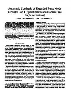
superposition of all possible states of the classical register. For a n-qubit quantum n register, its corresponding state is a normalized vector in a H2 space, |ψn i = n n P2 P2 −1 2 i=0 αi |ii, where i=0 |αi | = 1, i ∈ N. Quantum circuits are constrained networks of gates with no cloning and no feedback allowed [6]. The quantum gate is a physical device implementing an unitary operator that represents the quantum state transformation. Due to the unitary property, all quantum circuits are reversible and are considered the most feasible implementation for quantum algorithms. Fig.1 presents several quantum gates [1] used by our algorithm’s database.
|q1 i
|q1 i •
|q1 i
H
|q1 i ×
|q2 i
|q3 i ⊕
|q2 i ×
|q3 i
(c) TOFFOLI
(d) SWAP
|q1 i •
|q2 i •
|q2 i ⊕
(a) (b) CNOT HADAMARD
• F redkin
(e) FREDKIN
Fig. 1. Elementary gates
1.3
Proposed Approach
We present a new approach that facilitates the successful synthesis for different quantum circuit types that are described with real number matrix elements. The desired output function is provided to the synthesizer, and the tool computes whether a quantum circuit (composed of one or more quantum gates from our database), that implements the function, exists. The novelty of the approach lies in splitting the potential circuits in vertical levels called “sections” and horizontal levels called “planes” (Fig.2), for a consistent representation of the genetic algorithm, which is used for the chromosome definition. Information is exchanged from left to right with the upper wires representing the most significant qubits. Potential circuits are represented by individuals (Fig.3 (b)), each containing rows for possible gates on which the tensor product can be applied, and one column for the section decomposition. The number of gates on a row is limited by the number of circuit qubits. The number of gate elements within the column is not limited and the level of decomposition can be set interactively. Each individual represents a possible solution, which is computed by applying the tensor product for all horizontal rows and then multiplying all the results.
Automatic Synthesis for Quantum Circuits Using Genetic Algorithms section 1
section 2
3
section m plane 1 plane 2
plane n
Fig. 2. The quantum circuit view that is used for the new approach
2
Previous Work
As proposed previously [3], a four-phase design flow assists computations by transforming a quantum algorithm from a high-level language program into precisely scheduled physical actions. The first three phases are implemented by a compiler and the last phase is hardware dependent (in some cases can be just a simulator). The simulation and layout tools incorporate details of the emerging quantum technologies that would ultimately implement the algorithms described by higher level languages. In reference [10], Lukac and Perkowski have identified the following question: how the number of wires and the gate position within the circuit be encoded by employing the least complex data structure? They proposed a transformation of the quantum circuit in an encoded chromosome, in order to be used in a standard genetic algorithm. In the encoded chromosome the following rules are imposed: equal probability of presence of each gate type, fast encoding and decoding of an individual and no other parameters beside basic definitions (no control bits). The potential weak point is that beside the gate order, there is no information indicating what gates are connected to what wires. Thus, in order to obtain the chromosome, it is required that the quantum circuit be altered by employing swap gates. Rubinstein, in reference [11], considers for the genetic algorithm a scheme in which a gate has a type, a number of sets for the qubit operands and some sets of parameters for different categories (the generalised 2-qubit gate takes four real parameters for different types of rotations; the CNOT gate takes a number of control qubits, etc). The quantum circuit is considered as a list of gate structures, where the size of the circuit (number of gates) is variable. An application of a genetic algorithm for evolving quantum computing circuits has also been proposed in reference [4]. The genetic algorithm automatically searches for the appropriate circuit design that yields the desired output state. The fitness function compares the current output with the desired output, the search being stopped when a close match is found. Shende et al. proposed a top-down structure and effective computation by employing the Cosine-Sine Decomposition [5]. With the help of an optimized quantum multiplexor, a quantum analog Shannon decomposition of Boolean functions is derived, by applying this decomposition recursively to quantum
4
Cristian Ruican, Mihai Udrescu, Lucian Prodan, Mircea Vladutiu
operators. This leads to a circuit synthesis algorithm in terms of quantum multiplexors.
3 3.1
A New Genetic Algorithm Approach Implementation of Quantum Gates
The algorithm proposed in this paper operates with a collection of quantum gates, that are correspondingly encoded as matrices. A dynamic approach for the matrix representation (list-in-a-list) was used. This approach allowed for efficient memory usage due to different gate types used for synthesis. In order to decrease the time required by the Kronecker product and multiplication, we have created several dedicated memory locations for intermediate results storage. 3.2
The Genetic Algorithm
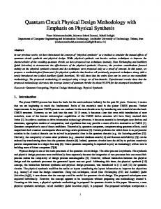
The special purpose algorithm [9] is used for the automated search of the best quantum gate composition, in order to implement a given quantum multi-qubit unitary transformation. Our main focus was to define all the phases required by the algorithm, allowing interactive specification of a minimal set of parameters, mainly those necessary for defining the exit point (algorithm stop condition) and those for increasing or decreasing the solution convergence (depending on mutation/crossover percentage, multiple mutation/crossover percentage). Fig.3 (a) presents our genetic algorithm. An important step in defining the fitness function (as percentage derived from the matrix comparison) was to find the best encoding for the chromosome (plane and section decomposition) by taking into account, at the same time, the matrix dynamic representation. For example, we compute in parallel the tensorial product for one individual on each section, and only after that we perform the multiplication between sections. This parallel execution of operations reduce the general computation time. 3.3
The Implementation
When encoding the chromosomes (Fig.3(b)), each individual will contain one or more sections, each section containing one or more gates. The number of gates is given by the number of qubits in the circuit, which is computed from the number of matrix elements (i.e. number of qubits = log2 (number of elements)). The number of sections is specified interactively and represents the granularity level of synthesis (a higher number of sections means that the circuit will be composed of elementary gates, and a small number of sections means that the algorithm will search in order to find more complex gates for synthesis). Depending on this parameter, we may find a solution. The approach randomly selects an individual, then picks a random gate solution. This gate solution will suffer a mutation, thus being replaced by a new
Automatic Synthesis for Quantum Circuits Using Genetic Algorithms
5
start
is input file valid
0
1 new population
selection
fitness evaluation
crossover
individual mutation
1 0
solution
new generation
section 1
gate
gate
gate
section 2
gate
gate
gate
0
1
section 3
end
(a)
(b)
Fig. 3. Genetic algorithm (a) and chromosome encoding (b)
randomly generated gate (all gates are defined in the input database). Because we allow multiple mutations, the same individual may suffer another mutation within the defined probability (Fig.4 (a)). This operator is very important when searching the problem space, in order to avoid being trapped in a local minimum of the fitness function. Also, we implemented a one-point crossover (Fig.4 (b)): two parents are randomly selected together with a point on their sections, and from that point all the gates between are swapped. The crossover results are used to improve the fitness value of the selected chromosome, allowing the exploration of a larger problem space.
individual
individual section 1
section 2
gate
gate
gate
gate
gate
section 1
gate
gate
gate gate
gate section 2
(a) The mutation
gate
gate section 1
section 2
section 3
individual
gate
(b) The crossover Fig. 4. Genetic operators
gate
gate
gate
gate
gate
6
Cristian Ruican, Mihai Udrescu, Lucian Prodan, Mircea Vladutiu
When implementing selection it is important to eliminate the individuals from the generation that manifest a small solution convergence. We used a proportional selection, so that an individual with a fitness value that is smaller than a threshold will be eliminated from the population, and a new one will be created randomly (intruder in population). We defined our fitness function as a matching percentage with the given output function by comparing each matrix element from our chromosome with each corresponding element from the expected solution. For instance if our chromosome has three out of four elements that are identical with the given output, the fitness function will be 0.75 .
4
4.1
Experimental Results
Two-Qubit Circuit
Suppose we have the following unitary transformation (1) as an output function:
10 0 1 0 1 −1 0 1 0 0 −1 01 1 0
(1)
and the algorithm is initialized with the default values, a solution will emerge immediately (Fig.5 (a)). If we repeat the algorithm, a second solution will emerge
|q1 i ⊕ H |q2 i
• (a)
•
|q1 i ⊕ • •
⊕
|q2 i
H
• ⊕⊕
• ⊕
(b)
Fig. 5. Circuit synthesis of equation (1)
implementing the same output function (Fig.5(b)); however it is no longer an optimal solution.
Automatic Synthesis for Quantum Circuits Using Genetic Algorithms
4.2
7
Three-Qubit Circuit
Suppose we have the unitary transformation (2) as an output function: 200 00 000 0 2 0 0 0 0 0 0 0 0 0 0 0 0 0 2 1 0 0 0 0 0 0 2 0 0 0 0 0 2 0 0 0 2 0 0 0 0 0 −2 0 0 0 0 0 −2 0 0 0 0 002 00 000
(2)
two solutions may be obtained by running our genetic algorithm, as shown in Fig.6.
|q1 i
⊕
•
•
|q1 i
H
|q2 i
•
•
⊕•
⊕
|q2 i
•
|q3 i
⊕
H
⊕
H
|q3 i
⊕
(a)
⊕
H
⊕ •
• (b)
Fig. 6. Circuit synthesis of equation (2)
4.3
Multi-Qubit Circuit
The algorithm successfully generates solutions for multi-qubit circuits (i.e. we emerged solutions for a 5-qubit circuit). 4.4
Benchmark
We used the benchmark proposed in reference [10] to compare our experimental results. Thus, we performed the following tests in the imposed conditions: onepoint crossover, mutation can erase, add, increase or decrease the chromosome length, the number of individuals is relatively small (50-100), the maximum number of generations is 50-100, the mutation probability is 0.2-0.6 and the crossover probability is 0.2-0.6. We used gates with 1, 2, 3 and 4 wires (see Table.1) with real elements. The tests where performed for 20 runs in total, the average result being used for comparison. The first test, described in Table.2 is intended to prove the algorithm convergence. All the gates are used with the defined scope of discovering similar
8
Cristian Ruican, Mihai Udrescu, Lucian Prodan, Mircea Vladutiu Table 1. Gates used in benchmark Number of inputs Gates 1 Wire, Hadamard, Pauli (X, Z) 2 CNOT, Swap, Controlled-Z 3 Toffoli, Fredkin
circuits. Each gate is used as target gate for the genetic algorithm and the expected result shall be the same gate, a smaller one or a circuit having the same function. Table 2. Test the convergence of our approach
Number of Population inputs per pM pC size q-gate 1-input 1-input 2-inputs 2-inputs 3-inputs 3-inputs
0.4 0.2 0.6 0.2 0.6 0.2
0.6 0.6 0.4 0.4 0.6 0.6
50 50 50 50 50 50
Real time Number of (average 20 Runtime (average generations runs) as in 20 runs) [10]