LATENT HEAT STORAGE FOR PROCESS HEAT APPLICATIONS J. Buschle, W.D. Steinmann, R. Tamme German Aerospace Center (DLR) Institute of Technical Thermodynamics, Pfaffenwaldring 38-40, 70569 Stuttgart, Gemany
[email protected]
1.
INTRODUCTION
Industrial process heat applications have been identified as a promising new area for applying thermal energy. Storage systems offer not only the reuse of thermal energy in cyclic processes which facilitates the integration of solar energy due to the availability of storage capacity. The bulk of process heat applications require steam at pressures between 1 and 20 bar with corresponding saturation temperatures between 100°C and 210°C. While the application of phase change materials (PCMs) is straightforward for isothermal energy storage, no commercial system is available in this temperature range today. The project PROSPER aims to develop cost effective PCM storage systems for process heat applications with a special focus on the concrete industry. Within this paper, different design concepts for PCM storage systems are addressed for the use of macroencapsulation of the storage material, composite materials or integration of layers made of materials showing a high thermal conductivity. The gas concrete production is presented as a possible application for PCM enhanced steam accumulators. Results from preliminary theoretical modelling are also discussed.
PHASE CHANGE MATERIALS (PCM) FOR PROCESS HEAT APPLICATIONS 3000
350 Dimethylol Propionic Acid
300 250 200
Adipic Acid
Pentaerythritol
LiNO3-NaNO3
KNO3-NaNO2NaNO3 Isomalt
time [sec.]
latent heat of fusion [kJ/kg]
2.
2500 h_e = 100 kJ/kg 2000
h_e = 300 kJ/kg
1500
150
1000 100
KNO3-NaNO2NaNO3
500
50 0 130
0 140
150
160
170
180
190
200
temperature [°C]
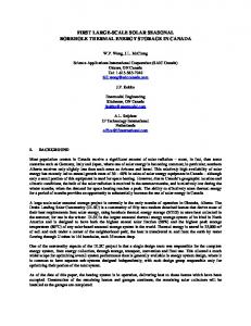
Figure 1: Candidate Phase Change Materials for process heat applications
0
5
10
15
k [W/mK]
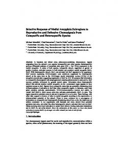
Figure 2: Solidification time for circular PCM layer around a tube as a function of thermal conductivity for two different values of latent heat of fusion
For the temperature range of interest, various materials can be used as PCMs. Examples of inorganic materials are technical salts and eutectic mixtures of these salts such as: lithium nitrate (LiNO3), lithium chloride (LiCl), potassium nitrate (KNO3), potassium nitrite (KNO2), sodium nitrate (NaNO3), sodium nitrite (NaNO2) and calcium
nitrate (Ca(NO3)2). In the group of organic PCMs an interesting material is Pentaerythritol. It undergoes a solidsolid transition at 189°C with an enthalpy of 269 kJ/kg [Benson, 1985]. The melting point of this plastic crystal is about 50 Kelvin above the solid-solid transition temperature. In Figure 1 the latent heat of fusion of different PCMs is plotted against the temperature. An important material property is the thermal heat conductivity of the storage material, which is significant for the performance of the storage unit during charging and discharging processes and determines the necessary heat transfer surface. The effect of the thermal heat conductivity is illustrated by the following example. In Figure 2 the solidification time, calculated with the analytical solution provided by R. Plank and Nesselmann [Baer, 2040] for a PCM layer around a tube, is plotted against the thermal conductivity of the PCM. Two PCMs with a latent heat of fusion (h_e) of 100 kJ/kg and 300 kJ/kg are compared. At the beginning of both cases the PCM is completely molten. The temperature inside the tube is set to 10 Kelvin below the solidification temperature. The tube has an outer diameter of 20mm and a wall thickness of 1mm. The thickness of the PCM layer for a PCM with a latent heat of fusion (h_e) of 100 kJ/kg is 20mm. The corresponding thickness for a PCM with a latent heat of fusion of 300 kJ/kg is 9mm. In both cases the same amount of thermal energy is stored. The heat capacity of the PCM is neglected because in this case the latent heat of fusion is the main mechanism of energy storage. Also neglected is the thermal convection resistance between tube wall and working fluid since it is small compared to the conduction resistance from the melting front to the separating wall. Below a thermal conductivity of 5 W/(mK), the PCM’s solidification time increases rapidly. Above 5 W/(mK) the improvement in solidification time is small. Due to the higher volumetric energy density for higher values of the latent heat of fusion, the average distance for the heat transfer is smaller and therefore the required thermal heat conductivity is lower.
3.
CONCEPTS FOR PCM STORAGE SYSTEMS
For a cost effective operation of thermal energy storage systems, a high power level during charging and discharging operations is necessary. All PCMs listed in Fig. 1 show a characteristic thermal conductivity below 1 W/(mK). Different concepts are investigated at DLR to overcome the limitations resulting from this low thermal conductivity. There are two basic solutions: - Increase of the heat transfer area - Increase of the effective thermal conductivity Graphite-foil
PCM
PCM
PCM
Steam pipe
PCM
Figure 3: Bundle of macroencapsulated PCM in tubes (diameter 25mm)
PCM
PCM
Figure 4: Schematic of concept using graphite foil as layers with high thermal conductivity
Figure 5: Segment for tubular storage made of PCM / Graphite composite material manufactured by SGL Technologies
A concept to increase the heat transfer area is the macro-encapsulation of the storage material. The capsules filled with PCM are stored in a pressure vessel filled with water and steam. Macro-encapsulation can be done with flexible or stiff capsules. In Figure 3 a bundle of pressure resistant tubes filled with PCM is shown. The tubes have an outer diameter of 25 mm and a length of 500 mm. Both sides are closed by welding. Because of the variations in specific volume of up to 10% during phase change, the tubes are not filled completely with the PCM. A gas volume fraction of about 20% is required inside the stiff capsules to limit the increase of pressure during the melting of the PCM. Due to the corrosive behaviour of the selected salt as PCM, a minimum wall thickness is necessary and no flexible encapsulation is possible [Abald, 1968]. The thermal conductivity of the PCM can be increased by integrating layers of highly conductive materials into the PCM (Figure 4). The layers are arranged in the direction of heat transport. A promising material for these layers is expanded graphite due to its high thermal conductivity (150 W/mK) and its corrosion resistance. The higher mass specific price of expanded graphite compared to stainless steel or carbon steel, is more than compensated by its low density and high thermal conductivity. The investment costs for extended heat transfer structures made of graphite foil are expected to be significantly lower than for steel. Another way to increase the thermal conductivity of the PCM is by mixing the PCM with a material of high thermal conductivity. Composite materials, as presented in Figure 5, are manufactured by compression of a powder mixture of technical salts and ground expanded graphite. Expanded graphite is chosen because of its high thermal conductivity and chemical stability. An important aspect here is the cyclic behaviour of the composite material. After repeated charging and discharging cycles, the separation of the components must not occur [Bauer, 2006] [do Couto Aktay, 2005].
4.
STEAM ACCUMULATOR
Due to increasing costs for fossil energy, systems for thermal energy storage have become attractive for process heat applications. Especially in cyclic processes, energy storage systems offer an additional option for efficient energy usage. An example for such a cyclic process is the production of gas concrete. Here the produced stones are hardened under a steam atmosphere in an autoclave. During a hardening cycle, the pressure in the autoclave is raised up to 15 bar for several hours. Between two production cycles, the steam is partially stored in varyingpressure accumulators, so called Ruths steam accumulators, which represent the current state-of-the-art technology in medium temperature thermal energy storage. Discharge pipe Savety valve
Water level gauge
Charging pipe
Charging nozzle Feed pipe
Connection to the distribution pipe
Circulation pipe
Holes
Circulation pipe
Drain
Figure 6: Varying pressure accumulator [Goldstern, 1970]
Figure 7: Charging nozzle with circulation pipe [Goldstern, 1970]
Varying-pressure accumulators are filled up to 80% with hot pressurised water to increase the storage capacity compared to direct steam accumulators. Liquid and gas phases are in thermodynamic equilibrium. During the discharge process, the energy needed for evaporation is provided by the sensible heat of the liquid medium, and the temperature and pressure in the storage vessel decrease. During the charging process, steam is blown into the liquid contained in the accumulator. The incoming steam bubbles condense in the liquid or pass into the steam space, depending on the thermodynamic equilibrium in the vessel. The bubbles which rise to the steam space increase the pressure and lead to a higher saturation temperature, so that the next bubble might condense. To use the entire storage content, the charging process requires circulation. Ruths invented a method that consists of nozzles (Figure 7) which turn the flow of steam upwards. The nozzles are surrounded by a circulation pipe, wherein the water flows upwards. The minimum temperature loss is composed of the difference between the steam space and the uppermost liquid layer as well as the difference between the saturation temperatures due to the additional pressure of the water at lower depths. Depending on the accumulator pressure and the steam intake, there is a certain depth for the nozzles which minimizes the overall temperature loss. [Goldstern 1970]
5.
PCM ENHANCED STEAM ACCUMULATOR
volume fraction [%]
wall thickness [mm]
The energy efficiency of gas concrete production can be increased by usage of isothermal steam storage. This can be achieved by using a PCM as storage material. Since the pressure vessels of the Ruths type storage system are already installed, one concept for a PCM storage is to use these pressure vessels and fill in encapsulated PCM. Pressure resistant tubes can be used for encapsulation. Alternatively the same tubes can be arranged in the form of a tube register with externally arranged PCM. These two concepts are compared with regard to the necessary wall thickness and solidification time. 1,6 1,4 1,2 1
100
80
60
0,8 0,6
40
external arranged PCM
external arranged PCM
0,4
internal arranged PCM
internal arranged PCM
20
0,2 0
0 2
6
10
14
18
22
26
30
pressure [bar]
Figure 8: Necessary wall thickness of a tube against pressure for steam pressure load inside (externally arranged PCM) and outside a tube (internally arranged PCM) with an outer diameter of 20mm.
0
100
200
300
400
500
600
time [s]
Figure 9: Solidified volume fraction of PCM against time inside and outside a tube with an outer diameter of 20mm and wall thickness of 1mm. The amount of PCM is in both cases the same.
In Figure 8 the necessary wall thickness of a tube with internally and externally arranged PCM, calculated according to the German technical standard TRD [VdTÜV, 2002], is plotted against pressure. The required wall thickness for an outer pressure load (internally arranged PCM) is always higher than for an inner pressure load (externally arranged PCM). The reason for this is a higher safety factor for outer pressure load. In the pressure range up to 30 bars the stress through buckling is dominating for an internally arranged PCM. The wall material is stainless steel. In Figure 9 the solidification behaviour of an internally and externally arranged PCM is presented. The solidification time is calculated using the analytical solution provided by R. Plank and Nesselmann [Baehr, 2004].
The temperature gradient between solidification temperature and wall temperature is 10 Kelvin. The latent heat of fusion of the PCM is 100 kJ/kg, the thermal heat conductivity is 5 W/(mK) and the density is 2000 kg/m³. The same amount of PCM that fills the tube arranged outside requires half the time for solidification than the PCM arranged inside the tube. These results indicate that arranging the PCM outside the tubes is more cost effective than filling the PCM into the tubes. For a complete analysis, the costs for the headers needed for the external arrangement have to be compared to the costs of the pressure vessel needed in the macroencapsulated concept. An example of such a PCM enhanced steam storage system built as a tube register with externally arranged PCM is shown in Figure 10.
Charging pipe PCM
Tube register
Water seperater Discharge pipe
To discharge the presented steam accumulator, water is pumped through the tube register and evaporated. Before the steam leaves the accumulator, the liquid part of the flow is removed in the water separator. During the charging process steam is condensed in the tube register. The condensate flows to the reservoir, which is arranged at a lower level. For a better outflow of the condensed water, the tube register is inclined. To prevent the pump from drainage during charging operation, a non-return valve is installed between the charging pipe and pump. The reservoir is a small pressure vessel and compensates the mass inflow and outflow during charging and discharging operations.
Feed pipe Pump
Reservoir
Figure 10: PCM steam storage
To upgrade an existing varying-pressure accumulator to an isothermal steam accumulator, macroencapsulated PCM can be inserted into the pressure vessel. This upgrade is also possible with a tube register with externally arranged PCM. Here the flow and the return pipe of the tube register are connected to the existing pressure vessel. A pump assures the circulation between the tube register and pressure vessel. The function of the reservoir and the water separator is provided by the pressure vessel of the varying-pressure accumulator.
6.
SIMULATION PCM ENHANCED STEAM ACCUMULATOR
For the design and construction of novel PCM steam accumulators, simulation models are written in an objectoriented simulation language for the modeling of physical systems [Steinmann, 2005]. Models are described by differential, algebraic and discrete equations. It is possible to combine detailed physical models of the PCM with a complete system simulation of the storage unit. For the simulation, the storage tube is discretized into control volumes in the axial direction. The PCM around the storage tube elements is further discretized in the radial direction (Figure 12). If we assume that the changes of kinetic and potential energy can be neglected we obtain an equation for the internal energy of the control volume of the tube
dU = hin ⋅ m& in − hout ⋅ m& out + Q& dt
Equation 1
In the control volume of the PCM only the heat flow is taken into account. Conservation of mass means that the change of mass in the control volume equals the difference between the mass entering the system and the mass leaving the system.
dm = m& in − m& out dt
Equation 2
In the control volume of the PCM the change of mass is set to zero. In Modelica it is a basic concept to connect models to each other by defined connectors which contain all important information that enables the Models to interact. Control volumes are connected by models that calculate the mass flow rate depending on the pressure difference and, respectively, the heat flow rate depending on the temperature difference between the two control volumes. To analyze the operating mode of the novel steam accumulator as presented in Figure 10, a simulation model in Modelica is built. In Figure 11 a screenshot is shown. In this example the examined tube register has 50 parallel tubes with a length of 5 meters. The diameter of the tubes is 20 mm and the distance between the tubes is 80 mm. The volume of the headers is 0.1 m³ and the volume of the water reservoir is 1 m³. The PCM has a melting range from 223 °C to 221 °C and a thermal conductivity of 5 W/(mK). Ramp2
duration=100
50
L
50
r d Ramp1 Power true duration=100
Figure 11: Simulation model of the PCM enhanced steam accumulator in Modelica
Figure 12: Radial and axial discretized storage tube with external arranged PCM
In Figure 13 the temperature of the PCM in five different distances to the tube wall is plotted. The PCM is initialised at a temperature of 224°C. In the pressurised parts, the water and steam content is initialised at a pressure of 25 bars and an enthalpy of 1000 kJ/kg. During the first thousand seconds, the discharging valve is closed. The pump is powered up during the first 100 seconds. The temperature in the whole storage system becomes uniform. After 1000 seconds the discharging valve is opened. The complete PCM is solidified 2200 seconds after opening the discharging valve.
temperature [°C]
4 mm
12 mm
20 mm
28 mm
36 mm
224 223 222 221 220 0
1000
2000
3000
4000
time [s]
Figure 13: PCM temperatures during discharging In Figure 14 the discharging power of the accumulator and the level in the reservoir is plotted against time. After opening the discharge valve, the storage unit has a peak in the discharging power. The reason for this is the short
distance for heat conduction between the melting front and the tube wall at the beginning of the discharging process. The storage power decreases strongly in the first 500 seconds. The water level in the reservoir increases after the discharging valve is opened. The reason therefore is that the tubes in the tube register are no longer completely filled with water because of the generated steam. During the discharging period, steam is taken from the accumulator and the level in the reservoir decreases. Level Reservoir 70
100
65
80
60
60
55
40
50
20
45
Level Reservoir [%]
Power [kW]
Power 120
0 0
1000
2000
3000
4000
time [s] Figure 14: Storage Power and water level in the reservoir during discharging
7.
CONCLUSION
With the simulation models presented in this work, PCM steam storage concepts can be analysed. Simulation results of a PCM steam accumulator with a tube register and externally arranged PCM are presented. In the next step, different simulation models will be developed for comparison. These simulation models will focus on using macro-encapsulation of the storage material, composite materials and the integration of layers made of materials showing a high thermal conductivity. Further validation of the models will be done using laboratory scale experiments. The aim of the work is to provide a dimensioning tool that enables to design the thermal behaviour of the steam accumulator. For example, using a tube register with externally arranged PCM, the number of tubes and their distance has to be defined, depending on the steam process the accumulator is integrated into.
ACKNOWLEDGEMENTS Part of the work presented in this paper has been funded by the Federal Ministry of Education and Reseach (BMWI) under the funding codes FKZ 032736017 (PROSPER).
REFERENCES Abald E. R. (1968). Corrosion Amsterdam/London/New York
Guide.
Second
Revised
Edition.
Elsevier
Publishing
Companiy,
Baehr H. D., Stephan K. (2004). Wärme- und Stoffübertragung. 4 ed. Berlin, Heidelberg: Springer. ISBN 3-54040130-X Bauer, T., do Couto Aktay, K.S., Christ, M., Öttinger, O., Tamme, R. (2006) PCM-Graphite Composites for High Temperature Thermal Energy Storages, ECOSTOCK 2006, Stockton, New Jersey, 31.5–2.6.2006 Benson, D.K., Burrows, R.W., Webb, J.D. (1985). Solid state phase transitions in Pentaerythritol and related polyhydric alcohols. Solar Energy Materials 13, pp 133-152
do Couto Aktay K. S., Tamme R., Müller-Steinhagen H. (2005). PCM-Graphite Storage Materials for the Temperature Range 100-300°C. Proceedings of the 2nd Phase Change Material and Slurry Conference, Yverdonles-Bains, 15 -17.07.2005. Goldstern, Walter (1970). Steam storage installations. Springer-Verlag OHG, Berling/Göttingen/Heidelberg SGL carbon group, www.sglgroup.com Steinmann, W.D., Buschle, J. (2005). Analysis of thermal storage systems using Modelica. Proceedings of the 4th International Modelica Conference, Hamburg, March 7-8, pp 331-337 Modeling of complex physical systems, www.modelica.org