Behavior-Based Acceptance Testing Of Software Systems: A Formal Scenario Approach P.Hsia, J. Gao, J. Samuel, D.Kung
Y.Toyoshima, and C. Chen
The Univ. of Texas at Arlington P.O.Box 19015 Arlington,TX 76019-0015
Fujitsu Network Transmission Systems, Inc. 3099 North First Street San Jose, CA 951342022
Abstract
consistency, and completeness of the teet catxs,and 6)
Acceptance testing is the determining factor in the eatisfaction of the contract between the eoftware vendor and the customer. In today’s industry practice, there is a lack of a syetematic method to help testers (or cuetomere) construct, form&, and verify accep tance testing modela, and use them for automatic teat caee generation. Thia paper propoeee a eystematic a p proach to form the acceptance test model for a so* ware aystem to represent ita external behavior from the use” perspectives. Baaed on the generated test model, Merent rigorous acceptance test criteria are defined, and varioue types of acceptance teating are diSCd. Keywords: Acceptance testing, scenario, scenario testing, test generation.
there are no methods to check if the acceptance testing plan matches the givea quirementa. There ha6 been a large quantity of literature add r h g acceptance testing in Merent ~ p e c t a .For example, Bill Hetrel[3] pointa out that the major murce of the acceptance testing casea is the syetem 28quirementafrom the users, and the primary focus is on usability and reliability. Thus, the user involvement in acceptance testing ie very important. Cem Kana at el@] believe that the acceptance testing plan should include mainstream testa for required functional featurea. Thus, the major testing t ~ k ain acceptance teat are: 1) to verify man-machine interactions, 2) to demonstrate the required functional featuree, 3) to examine the specified eptem constraints, and 4) to check the system’s external interfaeee (i.e. hardware inter-
1 Introduction Acceptance testing is one of the critical phaeee in the software life cycle. Verifying the external behavior of a noftware eystem is an eeeential part of accep tance testing. Unlike other types of W i n g (structured testing and integration testing), the major objective of acceptance testing is to demonstrate how well the constructed software system ratisiies the customer’e requirements. Acceptance testing focueee on verifying man-machine interactions, required function featuree, and specified syetem constraints. Currently, acceptance testing is conducted in an ad hoc manner. The major probleme of thia approach are: 1) the test plan generation reliea heavily on the understanding of the eoftware syetem, 2) there is a lack of formal test modela representing the complete external behavior of the eystem from the user perspective, 3) there is no methodology to produce all Merent usage pattern6 to exer& the external behavior of the eyetem,4) there is a lack of rigorous acceptance criteria, 5) there are no techniques for verirying the correctness,
0730-3157194$04.000 1994 IEEE
.
-.
~
~
facee).
In thia paper we introduce a new acceptance teat model - a formal scenario model to capture and r e p resent the external behavior of a eofiware ayetem. We discuaa acceptance test errom, test criteria, and teet generation. The major benefit of thia approach ia ita ability to allow u ~ e r ewith the quiremeata andysta to specify and generate the acceptance teat awes through a systematic approach.
2
Scenario-Based Acceptance Testing
In thia eection, we present a formal ecenariebaeed acceptance test model for testing the external be+ haviora of software system6 during eyetem acceptance teating. Thia test model ~ ~ ~ iofe three t a typea of submodela: 1) a wer mew, 2) an ezternol rvstem intqface, and 3) an ezternal $#stem mew. A wer view captures and repreaenta the external behavior of manmachine interactions for a particular u ~ e rgroup. The external behavior includea u8er’B eventa and related inpub (euch a6 commands and data) 86 w d 86 eye-
te”r responding events and related outpub (euch ae
view.
tables, reporte, and error measagea). The purpoee of a user view b to repnant the operational scenario acheme from the user’e viewpoint. An external syotem interface b umed to model the external behavior of the interactions between a system and one of ib i n t e r f d external ayetema. The objective here ia to rep-t the various external conditions in a particular hardware interface. An external view mod& the combination of the external behavior of a eyetem in terms of ita w viewe and external interface views. For any mftware system, the scenario-baaed accep tance testing model can be constructed in the following step: Step 1 Scenario elicitation and a p d c a t i o n where different uaer viewe and external interface viewe are elicited. Step 2 Test model formalization- where each external interface view in formalired ae a scenario-baaed tinite date machine (FSM),and they are merged together to form a aystem view the software aystem, which ia called a compoeite scenario-baeed finite etate machine
Dedinith An crtemal infedace meto r e p n a n b the bcbsvior d UI interface between a system and ib interfaced external repmenb the behavior in term6 of inpub (stimuli), outpub (rcsponeee), trig@ events, reactive evenb. An insta~ceof an external interface view conaisb of a eet of scenarios oeen h m the interface. Dedinition: An criernal ryrtem mew ia a ret of ecenario schema which repwsents the external view ofthe aydern in terms of ib user viewe and external interface viewe. An instance of an external ayatem view combto of a ret of concurrent, communicating ecenarior in the syotem. 2.1 Test Model Elicitation In thia subsection, we use a aimple PBX aystem in Figure 1 ae an example to illustrate how a test model can be elicited sccording to the aystem requirements and usera. The elicitation of a teat model for a eo% ware ayetem consists of the following etep:
-
-
0
(CFSM).
Step 3 Test model verification - where all generated FSMs and the CFSM are d e d in terms of determiniam, consistency, comctneee, and completeness. A detailed diecumion of FSM vetification can be found in [4]. Some baeic definitions about ecenarioe and related concepts are given below. More detaila can be found in [4]. Definition: An ewent ia a rp&c stimulus to a syetem ae a result of which either the etate of the ayatem ia changed and/or another event ia triggered. An ewcnt type defines all the poeeible events that have ”ilar attributes. Definition: A rcenario ia a concrete system ueage example conaiating of an ordered sequence of events which accompliehea a given functional requirement of the ayatem desired by the cuetomer/user. A scenario starts and ende with the name etate of the ayetem aa perceived by the w. Definition: A runario rdeme b a template of eeenarioe consisting of the eame ordered aequence of event types and accomplishing a given functional requirement of a ayatem. A runario instance ia an inetantiation of a acheme. Definition: A wer view ia a set of scenario schema m eeen by a certain group of users. The user view describes the interactive behavior of the user with the system. If the user b the agent for the ret of scenarios of a user view, the w view is d e d an rctiee wer
0
0
Step 1: Elicit user views Thia includes claeeifying the various user views sccording to the types of user group, and building their respective scenario treea. Step 2: Elicit external system interface view8 (a) IdentifL ezternal ryrtem intqfacee according to according to the rystem nquinmente. For example, a PBX eyetem in Figure 1 hae one external eyatem interface; that ia, the interface between the trunk goup circuit and the central switch eyetem. (3) Construct a runario tne for each eztemal system interface according to tbe wmpnhensive event t m u in tbe rystem rpecificatione. Construction of a scenario tree baaed on a given a m p m heneive event trace ia described the followinge u b sections. Step 3: Combine the generated r d o treee to form a scenario foreet.
All of the above etepe can be performed in etraighb fixward manner, except for the eonetruction of acenario trees. 2.1.1
Constructing A S User View
d o ! k m For A
Definition: Scenario Tree A scenario tree denoted T(V)= (N, E, L),for a user view V, consists of a finite set of nodes N , a finite
294
O.H/II:A.Il..
d u d Soma
.-.q $.
.......
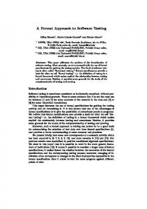
EFigure 2: Scenario tree for the CALLER view
Figure 1: Requirements for a simple PBX system our approach, the concept of interface ia introduced to
partition the i n t e r a c t i ~between ~ various subsystems and u%ere. For each interface, we conduct scenario elicitation in the following two step: 1) Derivation of rccnario tmcc, 2) CoRstruction of scenario tnc.
aet of edges E, and a finite set of edge lab& L. In particular, the root node denoted < S > ia the userperceived initial state of the syetem and ia called the initial node. All the leaf nodes are denoted M < S > nnd are called terminal nodes. The node ret consists of a aet of s t a h M perceived by the user. For every edge e E E between any two nodes, there in a label 1 E L aesociated with it, which is an event type. A 111bel 1 E L of an edge e E E between nodes N1,N2 E N shows that the state of the syetem changed fiom N1 to N2 due to the occurrence of the event type 1. The detailed construction of a scenario tree for a user view can be found in [4].
Derivation of Scenario Trace In thia otep, we model the interactions between any two rubsystems in terms of event flows (or sequencee). Events in the ecenario trace model can be any of three types, namely: 1) Outgoing meseage, 2) Incoming measage, 3) Reactive internal action ia any internal event that occurs M a response to another event. A scenario trace model has at least one starting and one ending event. In addition, an OR operator ia used M an OR constraint between multiple events to model the cam? in which only one of aeet ofeventa can occur. We illustrate our scenario trace model using the PBX example. Figure 3 bows the scenario trace model for the trunk interface in the PBX system. The trunk interface interacts with the PBX system and the central d t c h system. To construct the event trace between the PBX system and the trunk interface, the requirement analyst identifies all the interacting event typee (in this interface) fiom the requirements specifications (eg. high level data flow diagrams of the interface). He then claaaifies the identified events into start ing events, ending events, and intermediate events. In the example there iS one starting event - call request message and four possible ending eveate - call request ackflwy), call request ack(line congestion), ea11 n l e a c mcssagc(from PBX), call n l e u e mwagc(from
An Example coneider the example of the simple PBX system whoee requirements are given in Figure 1. Figure 2 shows the scenario tra for the CALLER view. The aet of all the patha from the initial node to each of the terminating nodes represents all of the p d b l e ecenariaa schema for a two party call. 2.1.2
Comtructing A Scanario I’ree For System External Interface
A
After identifying a system’s external interfaces based on the system requirements, the scenario elicitation for each external system interface is conducted by constructing the corresponding scenario tree based on a scenario tmcc mechanism. This scenario trace wechaniem ia an extension of Rumbaugh’s event trace [;!.In
295
PBX 9ymt.m
lkrL1I.C.rt.u
Cut..
Switch Syrtom
"i I I I I I I I I I I I I I I
I I I
-A
Figure 4: The Scenario ' h e for the "k Interface The notation S:A.System event demotea that the event is performed by the system on the interface A (either man-machine interface or external wtem interface). The absence of A i.e. S:System event denotes that the event ie performed by the system on the current interface itself. We u ~ the e "/" to indicate the triggering and trigged relationship between events. We use the "[Cl"to represents the guard condition for an event. The scenario tree ie constructed &om the scenario trace model discussed above. The detailed construction i o outlined in [5]. For the event trace example in Figure 3 the comsponding scenario tree is ohown in Figure 4. 2.2 Teet Model Formnlieation The test model formalisation c o ~ i e t of s two steps. In the first step, a scenario tree for a user view or an external system interface ie formalized into a finite state machine (FSM), called scenario FSm [4]. Then, these generated FSMa are combined to form a composite finite state machine (CFSM). The objective of this formalisation ie to use a FSM to model scenario echema and inatancm M that the test scenario6 can be analysed, verified, and generated in a systematic manner before acceptance testing. The scenario FSM io described in detail in [4]. Figure 6 ehows the FSM for the scenario tree in Figure 4. B e d on a given scenario FSM, we redefine a sa+ nario scheme as a scenario basis path from ita start state to its final state. A scenario instance ie an event transition sequence which exercieee a basis path of the scenario FSM. Dafinith: A Composite FSM A composite finite state machine, denoted as CFSM,
Figure 3: Scenario trace model for the trunk interface antml r u d d rgdem). The reet of the events are i n k mediate events. Beginning with each statting event, the requirement analyst constructs the flow of events (including internal reactive actions) until an ending event is reached. Mutually excldve eventa are r s solved ueing an OR notation. In the example the sttart ing event is a call nqvut mcuagc rent by the PBX system through the "ink h e . The central mitch system will respond with a call nquest ack meesage. If the meeeage is call n q u d clck (rwg) then the ey% tem will respond with an internal reactive action hrsy tone to the caller and will end the scenario aon. Similarly, the other poesible reaponsea are dealt with till an ending event b reached. This b similar to a depth first construction technique. The event sequences are continued till all the ending eventa are reached.
Scenario Tree Cmtruction The scenario tree for a nyatem external interface is very similar to the scenario tra for the user view. Every node in the tree indicstea state of the subsystem interface at that point in the event trace. An edge ie labeled in the format: Event := E w t i t e m / Eventitem I Eventitem Eventitem := ConditionJEwntitem I UnconditiondEventibrn ConditionaLEventitem := [ClUnconditiondEventitan UnconditiondEventikm := 8:Sptan a M t I S A S p t e m event
296
sting all the acenarioe of an FSM and exercising them one by
one and check the system’s behavior.
2) Testing ita external rystem interfaws to verify the i n t e r a ~ t between i~~ the eyutem and ita external system interfaces. Thir m achieved by executing Sll the reenarior in the conwponding FSM.
3) Testiry the requirad function f e s t m demonhow each function fdure io implemented in the @em. The idea outlined in [l]cau be adopted bere to carry out t h e t d n g . 4) Testing the rpecified qstem conetrainta aasurw the teater that aeveral syetern constraints like safety, timing and exceptions have ban met. During there e, we foam on the following differ-
&&ea
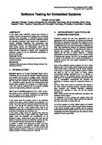
Figure 5: A CFSM for the PBX Switch Controller
aat mors:
e Urcr intemdion c w r r , which include: 1) incorrect prcrm#inl of user inputs, 2) inappropriate
pror#minl of diirerent operational se~ueneesof users, 3) incorrect system respoms, responding actions and output errors’. e
Eztcrnal rystcm interface emrr, which include: 1) incorrect protxxsing of incoming me% oages/stimuli, 2) inappropriate proceseing of different sequence of external events, 3) incorrect outgoing meeeagea/stimuli and output errors. E w r r , which include “ h g / e x t r a functional featurea and incorrect functional featuree.
e finctional
Figure 6: A Scenario ’ h e of the CALLEE View 0
is a set of related scenario FSM’s. Each scenario FSM
ie a concurrent part of ita composite FSM. Figure 5 shows a oimple example of a composite FSM which coneiete of four types of scenario FSM’s. This CFSM
captures the wrkrnal behavior of the PBX system.
Conatmint and ctccptior emmywhich include errors related to a eoftware system’s constraints, such an d e t y constraints, and exception constraints.
Each of the four acceptance teating ta&a satisfy certain criterion. The definitions of the Various teating aiteria are given below:
Definition: Interacting Scenario
Two or more rcenarioe in Merent FSM’s are called interacting if their companding baais paths interact with each other. For example, in Figure 6 the scenario bseie paths (in the Callee FSM ) involving the event oRE/S:A. Line dead tone interact with scenarioe baais paths in the Caller FSM through the triggered event S:A.Line dcod tone in the CALLER view.
Uler View Criterion: L d P be a roflwan rydcm, U be one of its wer view4 and G bc ibe dated FSM. A t a t ret Turrai.u for P a d i e v a the wer view criterion if for cocb h i s path of G it h at lead one sccnario indance covering the path. External System Inter€&- Criterion: 3 Testing External Behavior Let P be a roflwan ryrtcm, U be one of its d e m a l Acceptance teat for a software system ~ ~ ~ofk t qsr t e m interface, and G be the nlatcd FSM. A t a t ret several tach: T.ot.+ncl~~nr.r~,,cr for P achiever the edema1 rystem 1) Teirting its man-machine interfaca to verify the incosrsc( I Ohusability and reliablity of the aystem. Thin k t uncov.ble -, m output -, ,,era ~ e intemdion r e w r r . Thia teet involves generurd output stimuli. M-, output
-
297
f e
-
interface criterion if fw each krir path of G it h u 4t lead one rcenario i a d 4 n a cowering the patb. b c t i o n Criterion: Let P be a roftwan vatem, F be the ret of fvnctional featunr 4nd G’ be itn wmporite FSM. A teat ret Tfundionjiratbfiw the fbndion criterion if for each findional feutun f i E F it wverr 611 rcenario baaw potha (in each FSM of G’) which an rssociated with the fvnction featun f . Specified Conatraint Criterion: Let P be 4 rofrtuen ryrtem, C be the ret of v a t e m wutruiatr and G’ k its wmporite FSM. A teat ret Tcmrtrr(ntdaut& jiw the rpceifid wutruint criterion if for each ryrttm wautroiat ci E C it wverr all rcenario )orb p a t h (in cud FSM of G’) which am rssociatd witA tbe wnntroint ci.
ferent rigorow .ecepknce test criteria have been d a fined, and a scenario test generation method haa been provided. U& the approach, the customer can gencrate a acceptance tat plan “&ically to achieve Werent dected test “ g e . T h e vendor a#,bene fita h m this method in terms of test caee verification, testa automation, and test performance. We plan to further enhance our current rarearch teaulta and cxtend them to new areas, such aa dik tributed software @ems. We de0 plan to invdigate techniques to tat concurrent rreenarioe. We will start to implement thsee and future ideas aa a ocenarie based test tool.
6
4 Test Generation There haa been a number of test generation methode propoeed in the paat [l][2]. In order to exercise Werent types of scenario instances to achieve various criteria defined in the previous rection, we use the test generation approach deucribed in [5]. Using thie method all the scenarios in an FSM can be autom a t i d y generated. Figure 6 chows the FSM for the CALLER view and ita associated scenarioe.
7 References [l] M.Chandraeekharan, B Dasarathy, and Z.Kiehimoto, ”RequirementsBaned Testing of Rea-Time Systeme. Modeling for Testability,” IEEE Computer, pp. 71-80, April 1985. [2] T s S.~Chow, nTesting Software Deeign Modeled by FinitaState Machinee,” IEEE ‘hanesctions on Software Engineering, Vol. SE4,No.3, pp. 178-187, May 1978. [3] Bill H e t d , “The Complete Guide to Software Testing,” QED Information Science, Inc. Wellesley, M d u s e t t e 02181,1988. [4] Pei Hsia, Jayarajan Samuel, Jerry Gso, David Kung, Crb Chen, Yeeufumi Toyoahha, ” A Formal Approach to Scenario Analysis,” IEEE Software, March 1994. [5] Pei Heia, Jerry Zeyu Gm, Jayarajan Samuel, David Kung, Crb Chen, Yasufumi Toyaehima, ” Behavior-baaed Integration Teating for Sofwtare: A Formal Scenario Apporach,” Accepted by Third Internation Conference for System Integration in 1994, and will be published in the conference proceeding. [6] Cem Kaner, Jack Falk and Hung Quoc Nguyen, ”Testing Computer Software,” Second Edition, Van Noetrand Reinhold, New York, 1988. [7] James Rumbaugh, Michael Blaha, William Premerlani, Frederick Eddy and William Lorensen , “Object-Oriented Modeling and Design,” PrenticeBall International Editions, 1991.
Testing Interacted Scenario Bash P a t h When a scenario (Pa)in a FSM interacts with another scenario of a Merent FSM, it is ncce88Bfy to identify their interacting ecenarim and exercise them together with P,. [5] provides a detailed approach to identify and test interacting ecenarioe. The basic approach involves constructing a )oru path dependent matrit for a aet of related FSM’e and then generating the related rreenarioe.
5
Acknowledgment
The materid preeented in this paper ie based on work supported by the Tuaa Advanced Technology Program (Grant No. 003656-097), Fujiteu Network l h w m k i o n Systems, Inc., Hewlett-Packard Company, and the Software Engineering Center for Telecommunications at UTA. The authors want to thank the other members of the Object-Oriented Testiug Team in UTA for their help and effort.
Conclusion & Future Work
In t b paper, we have propoeed a systematic method for generating an acceptance testing plan and conducting acceptance testa. In our approach, accep tance testing coneiete of five steps: 1) test model elicitation, 2) teat model formalisation, 3) test model verification, 4) test case generation to achieve a selected teet criteria, and 5) test operations. In the paper, we have used a formal scenariebseed acceptance test model to capture and represent the external behavior of a software system in term of scenarios in different user views and external system viewe. The paper haa described how we can elicit, formalise, and verify a acceptance test model for a software system based the given system requiremenb and knowledge from ita usern. B e d on the constructed test model, dif-
298