In this paper we consider a platform (a vehicle, robot, car) moving with a planar motion. This vehicle has a number of cameras with different camera centres.
Camera platforms for localization and map building ˚ om Henrik Stewenius, Magnus Oskarsson and Kalle Astr¨ Centre for Mathematical Sciences, LTH. stewe, magnuso, kalle � @maths.lth.se Abstract Vision is useful for the autonomous navigation of vehicles. In this paper the case of a vehicle equipped with multiple cameras with non-overlapping views is considered. The geometry and algebra of such a moving platform of cameras are considered. In particular we formulate and solve structure and motion problems for a few novel cases of such moving platforms. For the case of two-dimensional retina cameras (ordinary cameras) there are two minimal cases of three points in two platform positions and two points in three platform positions. In the paper it is also discussed how classical algorithms such as intersection and resection can be extended to this new situation. We also present a system for feature detection, tracking and structure and motion estimation for such platforms. The theory has been tested on synthetic and real data with promising results.
1
Introduction
Vision is useful for the autonomous navigation of vehicles. We will in this paper adress the problem of estimating the position of the vehicle as well as the positions of world points using only image measurements. This is known as the structure and motion problem in computer vision. In robotics this problem is known as simultaneous localization and mapping, SLAM, or concurrent mapping and localization, CML. Most SLAM systems for robot navigation are based on sonar or laser range finders, but there are systems based on vision, cf. [2], and systems that use bearings, cf. [3]. For an overview of the SLAM problem see [7]. In this paper we consider a platform (a vehicle, robot, car) moving with a planar motion. This vehicle has a number of cameras with different camera centres facing outwards so that they cover different viewing angles. The purpose here is to get a large combined field of view using simple and cheap cameras. The cameras are assumed to have different camera centres but it is assumed that the cameras are calibrated relative to the vehicle. In [5] a similar setup was considered.
2
System overview
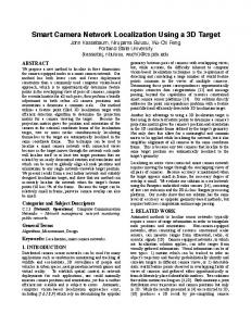
Consider � cameras that are fixed to a vehicle and consider images taken by these cameras at � different times, where the vehicle has moved. Assume that a number of corresponding points (possibly in different images) are measured. Then there are a number of problems that are interesting to look at. 1. Calibration. Assume that each camera sees enough points to calculate its own relative camera motion. Since the relative motion of all cameras is the same, how many cameras and views are needed to solve for the common motion. When is it possible to solve for the cameras’ relative positions? 2. Structure and motion. Assume that the camera’s position relative to the vehicle is known, but not the vehicle’s motion, represented by a transformation matrix ��� . Given a number of corresponding points, how should one calculate the world points � � and the transformations ��� from image data? 3. Intersection. Assume that the camera’s position relative to the vehicle is known, and that also the vehicle’s motion is known. Assume that a number of corresponding points are measured, how should one calculate the world points � � from image data? 4. Resection. Assume that the camera’s position relative to the vehicle is known, but not the vehicle’s motion, represented by a transformation matrix � � . Assume that a number of corresponding points (possibly in different images) are measured, how should one calculate the transformations � � from image data and known world points � �? In this paper we assume that the calibration of the cameras relative the vehicle has been done. In the experiments in section 5 the calibration was done manually. One could also consider autocalibration approaches similar to the approach in [1], where the problem of
U2
U3
P2
P3 P1
U1
P2 P3 P1
Figure 1: Three calibrated cameras with constant and known relative positions taking two images each aligning video sequences was adressed, or the calibration problems in robotics [8] which are similar in nature to the calibration of cameras relative a vehicle. The basic outline of our system is given in algorithm 2.1. Algorithm 2.1 SLAM 1. Track features. 2. Use RANSAC and minimal data to find initial estimates. 3. Extend solution using intersection and resection. 4. Optimize solution using bundle adjustment. We start by tracking features in the images. In our experiments we have used points. We then use the minimal cases described in section 3 to bootstrap the tracking and structure and motion estimation in a RANSAC [4] approach. One problem with RANSAC estimation is that one uses a minimal amount of data to estimate the model, which can lead to low accuracy. Since our vehicle is equipped with multiple cameras with a large combined field of view, we can get quite good initial estimates, see section 5. After an initial estimate has been found this is then extended and optimized using the techniques described in section 4.
3
Geometry and initial estimates
The standard pinhole camera model is used ������ ��� where the camera matrix � is a �
matrix. A scene point � is in ��� and a measured image point � is in ��� . It is sometimes useful to consider dual image coordinates. Each image point � is dual to two linearly � independent dual vectors ��� and ��� with � ����� . The measurement equation then becomes
� � � ����� � � �������
(1)
As the platform moves the cameras move together. This is modeled as a transformation � � between the first position and position � . In the original coordinate system the camera matrix for camera � at position � is � � � �. It is assumed here that the camera views do not necessarily have common points. In other words, a point is typically seen by only one camera. On the other hand it can be assumed that in a couple of neighboring frames a point can be seen in the same camera. Assume here that point ! is visible in camera � . The measurement equation for the � points is then
� � � � � ��� � � � � � �"!#��$%�&�'�&�(� �)�*���+$%�'�&�'�(� ��� -
� Note that , � �
(2)
�.� �� � � � corresponds to the viewing
plane in the vehicle coordinate system. Thus the constraint, in dual form, can be written
/
,0�� � � � � � � ,1�� � � � � �2�
��� �� �
!3��$4�&�'�&�(� �)�*�5�6$%�'�&�&�&� ���
(3) Here the planes , are measured. The question is if one can calculate structure � � and motion � � from these measurements. Based on the previous sections, the structure and motion problem will now be defined. Problem 1 Given � image points from � different platform positions � � � �7�8�9$%�&�'�&�'� ���:!;�@@A D � G B
$
E(F J �K� L � F M J� �N�PO � and � ���?>@ @AIH � � $ � G H� � � $ ��RQ JS�� M $2���
(4)
H
such that
� �T��� �U��� � � � � �4� for some
�
��
VW�5��$%�'�&�&�&� ���:!#�6$%�'�&�'�(� �
.
In order to understand how much information is needed to solve the structure and motion problem, one can calculate the number of degrees of freedom of the problem and the number of constraints given by the projection equation. Each object point has three degrees of freedom. Vehicle location for a planarily moving vehicle has three degrees of freedom when using �� Q J(�� ��$ , that is Euclidean information and four degrees of freeH this infordom in the similarity case when not using mation. The word “image” is used to mean “All the information collected by all our cameras at one instant in time”.
Table 1: The number of excess constraints � � M�� � Q � � M $���� for the structure and motion problem with � images of � points. n 1 2 3 4 5
1 -1 -2 -3 -4 -5
2 -2 -1 0 1 2
m 3 -3 0 3 6 9
4 -4 1 6 11 16
5 -5 2 9 16 23
For Euclidean reconstruction there are � � M�� � Q M $���� excess constraints and as seen in table 1 there are two interesting cases, namely “Two images and three points (m=2,n=3)” and “Three images and two points (m=3,n=1)”. These two problems can be solved and both cases lead to multiple solutions. The proofs are omitted due to lack of space.
��
Theorem 3.1 For three calibrated cameras that are rigidly fixed relative to each other, each taking an image of a point at two distinct times there generally exist one or three real non-trivial solutions. Theorem 3.2 Two cameras mounted rigidly with respect to each other for which calibration as well as relative positions are known are moved planarily to 3 different stations where they observe one point per camera. Under these circumstances there generally exist one or three non-trivial real solutions. For both cases pure translation is a degenerate case and can only be computed up to scale. The solution for the two problems leads to polynomials of low degree which can be solved quickly, robustly and accurately.
4
Refinement of solution
Intersection Generalization of the intersection algorithm [4] to this new situation is straightforward. When both calibration � �&�'�&�'� ��� and platform motion � �&�'�&�(� ��� is � � known it is straightforward to calculate scene points coordinates � from image measurements by intersecting view-lines. A linear initial solutions is obtained by solving E
� � � � � � G ����� �'�&� > � � � �� A
(5)
in a least squares sense. This solution can then be refined by non-linear optimization, cf. 4.
Resection Generalization of the resection algorithm [4] is slightly more complex since the view lines do not go through a common points (the focal point) as in the ordinary camera resection algorithm. Here we introduce a direct method for finding an initial estimate to the resection problem based on a linearized reprojection error. The idea is to solve � �
� � � � � � � � �:! ��$%�'�&�&� � which is linear in � . In our case there are non-linear constraints on � , so we use the theory for constrained optimization to find the optimal solution under the constraints. Parameterize the platform motion as in (4), using parameters � � � � JT� L � O � . The constraints � �� � � � � �U� � is linear in these parameters. The linear constraints H ����� ����� However there is a noncan be rewritten
� Q JS� M $ � � . Initial solution linear constraint ��� to the resection problem can be found by solving
�
� � � � � �� � (6) � � � Introduce the Lagrangian ! � � �S"�R� ��� � Q #�W� The solution to (6) can be found by $%! ��� . Here 2433 2433 $ � ! �'&)(+ ,% * -/.001 HLJ 5 Q .001 � H J 5 ����� (7) �� ��������� �
H�
� �
� � �
O
�
Here one may solve for � L � O6� and insert this in the above equation giving
� (
M
*
,87 � +
Q 4"9 �:& J H
-
��� �
(8)
Here there is a non-trivial solution to � � J;� if and , 7 only + � . if is one of the two eigenvalues of M ( * For these two solutions � � J;� is determined up to scale. H The scale can be fixed by � Q J � � $ . Finally � L � O � can be found from (8). H This gives a reasonably good H initial estimate on the resection parameters. This estimate is then improved by minimizing reprojection errors. Experience shows that only a few iterations are needed here.
Bundle adjustment The discussion in sections 3 and 4 focused on finding initial estimates of structure and motion, and it is necessary to refine these estimates using non-linear optimization or bundle adjustment, cf. [6, 4]. The generalization of bundle adjustment to platform motions is straightforward. One wants to optimize platform motions � � and scene points � � so that reprojection error is minimized. The fact that the platform has a very large field of view makes bundle adjustment much better conditioned than what is common.
0.015
0.01
Residual
0.005
0
−0.005
−0.01
−0.015
0
2000
4000
6000 Observation number
8000
10000
12000
Figure 2: Residuals in the reprojected images. 5
4
3
m
2
1
0
−1
−2
−7
5
−6
−5
−4
−3
−2 m
−1
0
1
2
3
Figure 3: Reconstruction seen from above.
References
Experimental verification
[1] Y. Caspi and M. Irani. Alignment of Non-Overlapping sequences. In Proc. 8th Int. Conf. on Computer Vision, Vancouver, Canada, pages 76–83, 2001.
A system with three video cameras was assembled a moved along a corridor with markers on the walls. Tracking was done by following these markers and some additional manual tracking. As stated in section 3 pure translation is a degenerate case for the initial solver in that it will give a solution which is unknown up to scale. However some turns in the path will fixate the scale. A reconstruction is shown in figure 3. The structure point which we seem to be passing through is a structure point which has a very high variance, as its measured view lines are almost collinear with the locations from which it is observed. The residuals in reprojection for this reconstruction are shown in 2. The size of the residuals are in the order of the error in a calibrated camera.
6
dard structure and motion problem in the sense that each time instant gives image measurements that correspond to view lines that not necessarily goes through the same point whereas in the standard structure and motion problem has view-lines that all go through the focal point. Two minimal cases for structure and motion estimation are solved, (i) three points in two views and (ii) two points in three views. Solution to the new type of resection problem is also given. Generalizations of the intersection algorithm and bundle adjustment are straightforward. Using these new solutions a system for feature detection, tracking, initial estimation, extension and bundle adjustment is presented. Solutions to the minimal problems are useful for structure and motion estimation of autonomous vehicles equipped with multiple cameras. The existence of a fast solver for the two images and three points case is of interest when computing RANSAC. It is important to note that pure translation is a degenerate case and that the solution in this case suffers from the same unknown scale as for single camera solutions. Another important aspect is that the cameras have to have separate focal points. In this paper the problem of calibrating the relative positions of the cameras on the platform is not studied. This is topic for further studies.
Conclusions
In this paper we have introduced the structure and motion problem for the notion of a platform of moving cameras. This problem is a generalization of the stan-
[2] A. J. Davison and N. Kita. Sequential localisation and map-building in computer vision and robotics. In SMILE 2000 Workshop, Dublin, Ireland, pages 218–234, 2000. [3] M. C. Deans and M. Hebert. Experimental comparison of techniques for localization and mapping using a bearing-only sensor. In 7th intl. symp. on experimental robotics, Hawaii, USA, 2000. [4] R. I. Hartley and A. Zisserman. Multiple View Geometry in Computer Vision. Cambridge University Press, 2000. [5] R. Pless. Using many cameras as one. In Proc. Conf. Computer Vision and Pattern Recognition, Madison, USA, 2003. [6] C. C. Slama. Manual of Photogrammetry. American Society of Photogrammetry, Falls Church, VA, 1980. [7] S. Thrun. Robotic mapping: A survey. In G. Lakemeyer and B. Nebel, editors, Exploring Artificial Intelligence in the New Millenium. Morgan Kaufmann, 2002. [8] H. Zhuang, Z. Roth, and R. Sudhakar. Simultaneous robot/world and tool/flange calibration by solving homogeneous transformations of the form ax=yb. IEEE Trans. on Robotics and Automation, 10(4):549–554, 1994.