Chapter 2: The Database Development. Process. Modern Database
Management. 9th Edition. 9 Edition. Jeffrey A. Hoffer, Mary B. Prescott,. Heikki
Topi.
Chapter 2: The Database Development Process Modern Database Management 9th Edition Jeffrey A. Hoffer, Mary B. Prescott, Heikki Topi © 2009 Pearson Education, Inc. Publishing as Prentice Hall
1
Objectives
D fi iti off terms Definition t Describe system development life cycle E plain prototyping Explain p otot ping approach app oach Explain agile software development approach Explain roles of individuals Explain three three--schema approach Explain role of packaged data models Explain three three--tiered architectures Explain scope of database design projects Draw simple data models
Chapter 2
© 2009 Pearson Education, Inc. Publishing as Prentice Hall
2
Enterprise Data Model
First step in database development Specifies scope and general content Overall p picture of organizational g data at high g level of abstraction Entity--relationship diagram Entity Descriptions of entity types R l ti Relationships hi between b t entities titi Business rules
Chapter 2
© 2009 Pearson Education, Inc. Publishing as Prentice Hall
3
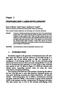
Figure 2-1 Segment from enterprise data model
Enterprise data model describes the highg level entities in an organization and the relationship l i hi between b these entities
Chapter 2
© 2009 Pearson Education, Inc. Publishing as Prentice Hall
4
Information Systems Architecture (ISA)
Conceptual blueprint for organization’s desired information systems structure Consists of:
Data (e.g. Enterprise Data Model–simplified ER Diagram) ag a ) Processes–data flow diagrams, process decomposition, etc. Data Network–topology diagram (like Fig 1-7) People–people management using project management g tools (Gantt ( charts,, etc.)) Events and points in time (when processes are performed) Reasons for events and rules (e (e.g., g decision tables)
Chapter 2
© 2009 Pearson Education, Inc. Publishing as Prentice Hall
5
Information Engineering
A data data--oriented methodology gy to create and maintain information systems Top--down planning Top planning– –a generic IS planning methodology th d l for f obtaining bt i i a broad b d understanding of the IS needed by the entire organization Four steps to TopTop-Down planning:
Planning g Analysis Design Implementation
Chapter 2
© 2009 Pearson Education, Inc. Publishing as Prentice Hall
6
Chapter 2
© 2009 Pearson Education, Inc. Publishing as Prentice Hall
7
Identify Strategic Planning Factors ((Table 2-2)
Organization goals– goals–what we hope to accomplish Critical success factors– factors–what MUST work i order in d for f us to t survive i Problem areas– areas–weaknesses we now have
Chapter 2
© 2009 Pearson Education, Inc. Publishing as Prentice Hall
8
Identifyy Corporate p Planning g Objects (Table 2-3)
Organizational units units– –departments Organizational locations Business functions– functions–groups of business p processes Entity types– types–the things we are trying to model for the database Information systems– systems–application programs
Chapter 2
© 2009 Pearson Education, Inc. Publishing as Prentice Hall
9
Develop Enterprise Model
Functional decomposition
Iterative process breaking system description into finer and finer detail
Enterprise data model
Planning matrixes
Describe interrelationships between planning objects
Chapter 2
© 2009 Pearson Education, Inc. Publishing as Prentice Hall
10
Chapter 2
© 2009 Pearson Education, Inc. Publishing as Prentice Hall
11
Planning Matrixes
D Describe ib relationships l i hi between b planning l i objects in the organization Types of matrixes:
Location--to Location to--function Unit--to Unit to--function IS--to IS to--data entity Supporting functionfunction-to to--data entity IS--to IS to--business objective
Chapter 2
© 2009 Pearson Education, Inc. Publishing as Prentice Hall
12
Example Business FunctionFunction-to to-Data Entity Matrix (Fig (Fig. 2-3)
Chapter 2
© 2009 Pearson Education, Inc. Publishing as Prentice Hall
13
Two Approaches to Database and IS Development
SDLC
System Development Life Cycle Detailed wellDetailed, well-planned development process Time--consuming, but comprehensive Time Long o g development d op cycle y
Prototyping
Rapid application development (RAD) Cursory attempt at conceptual data modeling Define database during g development p of initial prototype Repeat implementation and maintenance activities with new prototype versions
Chapter 2
© 2009 Pearson Education, Inc. Publishing as Prentice Hall
14
Systems Development Life Cycle (see also Figures 2.4, 2.5) Planning A l i Analysis Logical Design Physical Design Implementation Maintenance
Chapter 2
© 2009 Pearson Education, Inc. Publishing as Prentice Hall
15
Systems Development Life Cycle (see also Figures 2.4, 2.5) (cont.) Purpose–preliminary understanding Deliverable–request for study
Planning Planning A l i Analysis
Logical Design Physical Design
Database activity– enterprise modeling and early conceptual data modeling Chapter 2
Implementation
© 2009 Pearson Education, Inc. Publishing as Prentice Hall
Maintenance
16
Systems Development Life Cycle (see also Figures 2.4, 2.5) (cont.) Purpose–thorough Purpose thorough requirements analysis and structuring Deliverable–functional system specifications
Planning
AAnalysis Analysis A ll ii Logical Design Physical Design
Database activity–thorough and integrated conceptual data modeling
Chapter 2
Implementation
© 2009 Pearson Education, Inc. Publishing as Prentice Hall
Maintenance
17
Systems Development Life Cycle (see also Figures 2.4, 2.5) (cont.) Purpose information requirements elicitation Purpose–information and structure Deliverable–detailed design specifications
Planning A l i Analysis
Logical Design Logical Design Physical Design
Database activity– logical database design (transactions, forms, displays, views, data integrity and security) Chapter 2
Implementation
© 2009 Pearson Education, Inc. Publishing as Prentice Hall
Maintenance
18
Systems Development Life Cycle (see also Figures 2.4, 2.5) (cont.) Purpose–develop Purpose develop technology and organizational specifications Deliverable–program/data structures, t t ttechnology h l purchases, h organization redesigns
Planning A l i Analysis Logical Design
Physical Design Physical Design Database activity– physical database design (define database to DBMS, physical data organization, database processing programs) Chapter 2
Implementation
© 2009 Pearson Education, Inc. Publishing as Prentice Hall
Maintenance
19
Systems Development Life Cycle (see also Figures 2.4, 2.5) (cont.) Purpose programming, testing, training, Purpose–programming, installation, documenting Deliverable–operational programs, documentation training materials documentation,
Planning A l i Analysis Logical Design
Physical Design
Database activity– database implementation, including coded programs, documentation, installation and conversion Chapter 2
Implementation Implementation
© 2009 Pearson Education, Inc. Publishing as Prentice Hall
Maintenance
20
Systems Development Life Cycle (see also Figures 2.4, 2.5) (cont.) Purpose–monitor, repair, enhance Deliverable–periodic audits
Planning A l i Analysis
Logical Design Physical Design
Database activity– database maintenance, performance analysis and tuning, error corrections Chapter 2
Implementation Maintenance Maintenance
© 2009 Pearson Education, Inc. Publishing as Prentice Hall
21
Prototyping Database Methodology (Figure 2.6)
Chapter 2
© 2009 Pearson Education, Inc. Publishing as Prentice Hall
22
Prototyping Database Methodology (Figure 2.6) (cont.) (cont )
Chapter 2
© 2009 Pearson Education, Inc. Publishing as Prentice Hall
23
Prototyping Database Methodology (Figure 2.6) (cont.) (cont )
Chapter 2
© 2009 Pearson Education, Inc. Publishing as Prentice Hall
24
Prototyping Database Methodology (Figure 2.6) (cont.) (cont )
Chapter 2
© 2009 Pearson Education, Inc. Publishing as Prentice Hall
25
Prototyping Database Methodology (Figure 2.6) (cont.) (cont )
Chapter 2
© 2009 Pearson Education, Inc. Publishing as Prentice Hall
26
CASE
Computer-Aided Software Engineering Computer(CASE)– (CASE) –software tools providing automated support for f systems d development l Three database features:
Data modeling– modeling–drawing entity entity--relationship diagrams Code generation– generation–SQL code for table creation Repositories– Repositories –knowledge base of enterprise information
Chapter 2
© 2009 Pearson Education, Inc. Publishing as Prentice Hall
27
Packaged Data Models
Model components that can be purchased, customized and assembled into fullcustomized, full-scale data models Advantages
Reduced development time Higher model quality and reliability
Two types:
Universal data models Industry--specific data models Industry
Chapter 2
© 2009 Pearson Education, Inc. Publishing as Prentice Hall
28
M Managing i Projects P j t
Project P Project– j t–a planned l d undertaking d t ki off related l t d activities to reach an objective that has a beginning and an end Involves use of review points for:
V lid ti off satisfactory Validation ti f t progress Step back from detail to overall view R Renew commitment it t off stakeholders t k h ld
Incremental commitment commitment– –review of systems t d development l t project j t after ft each h development phase with rejustification after each phase
Chapter 2
© 2009 Pearson Education, Inc. Publishing as Prentice Hall
29
Managing Projects: People Involved
Chapter 2
Business analysts y Systems analysts Database analysts and data modelers Users Programmers Database architects Data administrators Project managers Other technical experts © 2009 Pearson Education, Inc. Publishing as Prentice Hall
30
Database Schema
External Schema
Conceptual Schema
User Views Subsets of Conceptual Schema Can be determined from businessbusiness-function/data entity e t ty matrices at ces DBA determines schema for different users E-R models– models–covered in Chapters 3 and 4
Internal Schema
Chapter 2
Logical structures– structures–covered in Chapter 5 Physical y structures–covered in Chapter structures– p 6 © 2009 Pearson Education, Inc. Publishing as Prentice Hall
31
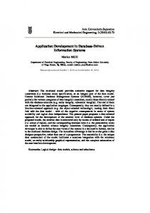
Figure 2-7 Three-schema architecture Different people have different views of the database…these are the external schema
The internal schema is the underlying design and i l implementation i
Chapter 2
© 2009 Pearson Education, Inc. Publishing as Prentice Hall
32
Chapter 2
© 2009 Pearson Education, Inc. Publishing as Prentice Hall
33
Chapter 2
© 2009 Pearson Education, Inc. Publishing as Prentice Hall
34
Pine Valley Furniture
Segment of project data model (Figure 2-11) Chapter 2
© 2009 Pearson Education, Inc. Publishing as Prentice Hall
35
Figure 2-12 Four relations (Pine Valley Furniture)
Chapter 2
© 2009 Pearson Education, Inc. Publishing as Prentice Hall
36
Figure 2-12 Four relations (Pine Valley Furniture) (cont.)
Chapter 2
© 2009 Pearson Education, Inc. Publishing as Prentice Hall
37
All rights reserved. No part of this publication may be reproduced, stored in a retrieval system system, or transmitted transmitted, in any form or by any means means, electronic electronic, mechanical, photocopying, recording, or otherwise, without the prior written permission of the publisher. Printed in the United States of America.
Copyright © 2009 Pearson Education, Inc. Publishing as Prentice Hall
Chapter 2
© 2009 Pearson Education, Inc. Publishing as Prentice Hall
38